manuals.online logo
Brands
  1. Home
  2. •
  3. Brands
  4. •
  5. Patterson-Kelley
  6. •
  7. Boiler
  8. •
  9. Patterson-Kelley MACH C1500 User manual

Patterson-Kelley MACH C1500 User manual

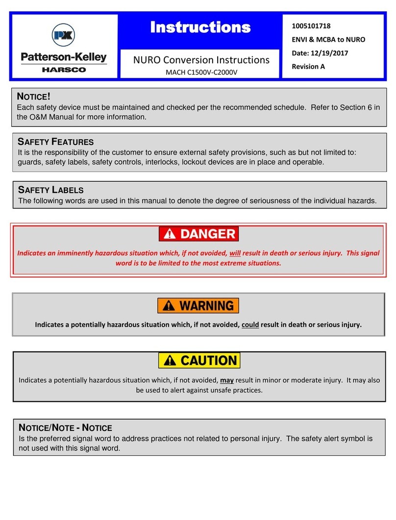
Instructions
1005101738
ENVI to NURO
Date: 12/19/2017
Revision A
NURO Conversion Instructions
MACH C1500-C2000H
Indicates a potentially hazardous situation which, if not avoided, may result in minor or moderate injury. It may also
be used to alert against unsafe practices.
Indicates an imminently hazardous situation which, if not avoided, will result in death or serious injury. This signal
word is to be limited to the most extreme situations.
Indicates a potentially hazardous situation which, if not avoided, could result in death or serious injury.
NOTICE!
Each safety device must be maintained and checked per the recommended schedule. Refer to Section 6 in
the O&M Manual for more information.
SAFETY FEATURES
It is the responsibility of the customer to ensure external safety provisions, such as but not limited to:
guards, safety labels, safety controls, interlocks, lockout devices are in place and operable.
SAFETY LABELS
The following words are used in this manual to denote the degree of seriousness of the individual hazards.
NOTICE/NOTE -NOTICE
Is the preferred signal word to address practices not related to personal injury. The safety alert symbol is
not used with this signal word.
Instructions
1005101738
ENVI to NURO
Date: 12/19/2017
Revision A
NURO Conversion Instructions
MACH C1500-C2000H
If the information in these instructions are not followed, fire or explosion may result causing property damage,
personal injury, or loss of life.
It is essential to read, understand, and follow the recommendations of these instructions before installing, operating
or servicing this equipment. Failure to do so could result in personal injury or death.
Installation and service must be performed by a qualified and knowledgeable individual who has been certified on the
P-K MACH®boiler. The features which permit this boiler to achieve high-efficiency performance can be misused
which could result in personal injury or death.
Lockout/tagout procedure must be employed when servicing this unit. Failure to do so could result in electrocution,
injury, or death.
Label all wires prior to disconnection when servicing controls. Wiring errors can cause improper and dangerous
operation.
Use care when reassembling main gas line and ensure all connections are tight. Use a leak detector to check for
leaks before and after servicing any component of the gas piping. Failure to do so could result in injury or death.
Use care when servicing boiler to prevent the accumulation of gas in or around the combustion chamber. Pockets of
accumulated gas are subject to combustion and/or explosion which could result in injury or death.
Installation must be in strict conformance to all applicable codes and standards including NFPA54, ANSI Z223.1 and
CAN/CSA B.149.
Instructions
1005101738
ENVI to NURO
Date: 12/19/2017
Revision A
NURO Conversion Instructions
MACH C1500-C2000H
TOOLS Required
•Phillips Head Screwdriver
•Drill and Drill Bit Set
•Adjustable Wrench
•Set of Nut Drivers SAE
•Torx set SAE
•Multimeter
•Gas Analyzer
1. Lock out Tag out all electrical connections and gas supply to appliance. There may be
multiple power sources.
2. Open front door of appliance and remove side panels.
3. Remove terminal block covers. Identify and label all current field wiring on boiler when
disconnecting.
4. Remove 7/16” nuts as required that hold top panel on as shown in Figure 1. Top panel
will need to be lifted at least 2” in front in order to remove front panel.
NOTE: If Cascading multiple appliances, convert all to NURO controls for ideal
operation.
Wire runs and devices connected to the Air Damper Interlock, Auxiliary Input, or Start Interlocks MUST be
rated for 120 VAC.
NOTE: DHW Flow switch terminals are not available.
NOTE: Analog input for the NURO controller must be 4-20mA.
NOTE: If using a Protocol Converter or MODBUS, contact the factory for support.
Instructions
1005101738
ENVI to NURO
Date: 12/19/2017
Revision A
NURO Conversion Instructions
MACH C1500-C2000H
5. Using a 1/8” drill bit, drill out rivets that fasten high and low voltage terminal blocks.
6. Remove 7/16” nuts from 4 inside corners of front frame assembly as shown in Figure 2.
Remove
7/16” nuts
Figure 1
Instructions
1005101738
ENVI to NURO
Date: 12/19/2017
Revision A
NURO Conversion Instructions
MACH C1500-C2000H
7. Remove 3 T30 Torx screws from front frame as shown in Figure 3. Remove front frame.
Remove
7/16” nuts
Figure 2
Instructions
1005101738
ENVI to NURO
Date: 12/19/2017
Revision A
NURO Conversion Instructions
MACH C1500-C2000H
8. With a T30 Torx bit, loosen 3 screws that hold control panel in place shown in Figure 3.
Figure 3
Loosen T30 Torx screws to control panel
Remove T30 Torx screws to front frame
Instructions
1005101738
ENVI to NURO
Date: 12/19/2017
Revision A
NURO Conversion Instructions
MACH C1500-C2000H
8. Disconnect all wires from internal safety devices and sensors. Take note to wire colors
for sensors as new panel will use same colors for sensor wires.
9. Control panel can now be slid right, lifted off screws, and removed from boiler.
10. Using a 1/2” wrench, remove and replace high and low gas pressure switches (Figure 4)
provided in kit. Be sure to apply gas thread sealant to new switches (Figure 5).
Replace existing
high and low gas
pressure switches
Figure 4
Figure 5
Instructions
1005101738
ENVI to NURO
Date: 12/19/2017
Revision A
NURO Conversion Instructions
MACH C1500-C2000H
11. Install heat exchanger sensor on front section of exchanger. Sensor only needs to be
finger tight. DO NOT OVERTIGHTEN SENSOR.
Heat exchanger sensor
Figure 6
Instructions
1005101738
ENVI to NURO
Date: 12/19/2017
Revision A
NURO Conversion Instructions
MACH C1500-C2000H
12. Install new control panel in place of old one and tighten down T30 Torx bit screws.
13. Install both electrical boxes facing front of boiler using supplied T20 self-tapping Torx
screws.
14. Run all internal wires to appropriate safety devices and sensors.
Types of Wires
Colors/Identification
Return Temperature Sensor Wires
Blue/Gray
Supply Temperature Sensor Wires
Red/Gray
Flue Temperature Sensor Wires
Yellow/Gray
Heat Exchanger Sensor Wires
Orange/Gray
Please refer to wiring diagram for any other connections. Ensure all wiring matches
supplied wiring diagram.
Figure 7
Instructions
1005101738
ENVI to NURO
Date: 12/19/2017
Revision A
NURO Conversion Instructions
MACH C1500-C2000H
15. Run igniter wire and ground to ignition electrode. Install gas valve plug with retaining
screw. High and low gas pressure switches will have matching electric connectors that
will need to be plugged in. Install high limit safety probe in thermal well of supply elbow.
BE SURE NOT TO PINCH OR KINK PROBE COPPER TUBE.
16. Install tubing for air switch and blocked flue switch. Blocked flue tube will need to be cut
to length to ensure that there is not tube slack. Tube should be pitched down from
switch to condensate pan to ensure condensate will not accumulate in tube.
Air switch tube should be
installed on top (-) port
High Back Pressure /
Blocked flue tube should
be installed on bottom
(+) port
NOTE: Verify the orifice pieces are installed in the pressure switches.
Figure 8
Ensure the high back pressure tube continually slopes down from the switch to the condensate pan. If the tube
“traps” moisture then the switch will not function properly.
Instructions
1005101738
ENVI to NURO
Date: 12/19/2017
Revision A
NURO Conversion Instructions
MACH C1500-C2000H
17. Install front frame assembly with (4) 7/16” nuts in each corner from inside of cabinet.
18. Install (3) T30 Torx screws along bottom of front frame assembly.
19. Install front door on hinge pins.
20. Install NURO touch screen assembly on door in order of nylon washer, NURO, nylon
washer, nylon lock nut as shown in Figure 10.
Install 7/16” nut
Figure 10
Figure 9
Instructions
1005101738
ENVI to NURO
Date: 12/19/2017
Revision A
NURO Conversion Instructions
MACH C1500-C2000H
21. Insert green electric plug D1 and D2 into NURO control and attach all ground wires to
front door ground lug.
22. Install field wiring to new terminal boxes per wiring terminal block labels.
23. Install terminal box cover and secure with 4 Phillips head screws.
Figure 11
Instructions
1005101738
ENVI to NURO
Date: 12/19/2017
Revision A
NURO Conversion Instructions
MACH C1500-C2000H
Figure 13
Heat Exchanger Sensor and Wires
Figure 12
Gas Valve and Wires
Instructions
1005101738
ENVI to NURO
Date: 12/19/2017
Revision A
NURO Conversion Instructions
MACH C1500-C2000H
Figure 14
Figure 15
Low Water Cut Off
Blower Plugs
Instructions
1005101738
ENVI to NURO
Date: 12/19/2017
Revision A
NURO Conversion Instructions
MACH C1500-C2000H
24. Re-energize power to unit. DO NOT ENERGIZE GAS. Call tech support for help pairing
controls to boiler (570-421-7500 and press 2 for technical support).
25. After pairing is complete with technical support, re-energize gas supply to unit.
26. Perform Runout Procedure.
27. Perform factory start up and fill out start up report located in O&M manual and check all
safety devices per O&M manual to ensure all are working properly.
28. Re-Install side and top panels of boiler.
Figure 17
Ignitor Ground Wires
High Limit Probe
Figure 16
Instructions
1005101738
ENVI to NURO
Date: 12/19/2017
Revision A
NURO Conversion Instructions
MACH C1500-C2000H
Runout Procedure
1. Remove the factory jumpers / field wiring from enable/disable, start interlock 1, start
interlock 2, damper end switch terminals.
2. From the information screen on the NURO touch screen verify that the enable/disable
circuit is open.
3. Reinstall the factory jumper or the field wiring in the enable/disable terminals and give
the boiler a call for heat. Verify that the boiler is giving the error of start interlock 1 open.
4. Turn the boiler off and reinstall the factory jumper or field wiring into the start interlock 1
terminals.
5. Turn the boiler back on, reset the error and verify the boiler is going into a start interlock
2 open error.
6. Turn the boiler off and reinstall the jumper or field wiring in the start interlock 2 terminals.
7. Turn the boiler on, reset the error and allow the boiler to try and start. Verify that the
boiler locks out on damper end switch did not close in allotted time.
8. Turn the boiler off and reinstall the factory jumper or damper end switch wires. Turn the
boiler back on and reset the control.
9. In order to test the low water cut-out, press and hold the red “Push to Test” button for at
least 5 seconds. A manual lockout reset error displaying 10010: “Low Water Limit” on
the NURO touchscreen should occur. The red LED indicator on the Low Water cut-off
will no longer be illuminated.
10. Optional Test Method: First turn the boiler off, and then turn off the boiler’s circulating
pump. Isolate the boiler from the system. Drain the water level below the low water cut-
off probe. Turn the boiler back on. It should not operate, and a manual lockout reset
error displaying 10010: “Low Water Limit” on the NURO touchscreen should occur. The
red LED indicator on the Low Water cut-off will no longer be illuminated.
11. Return the system to normal operation by refilling with water, restarting the boiler’s
circulating pump, and then turning the boiler back on.
12. The boiler is furnished with a low gas pressure switch, installed near the boiler’s main
gas shutoff/control valve. The operation of this switch must be checked as follows:
1. Close the main gas cock (external to the boiler).
2. Cycle the boiler on by generating a heat request.
3. Allow the boiler to proceed through prepurge and attempt ignition.
When the main gas shutoff/control valve opens to attempt ignition, the low gas
pressure switch will trip, causing the NURO touchscreen to display 10012: “Low
Gas Limit”. Even after re-opening the main gas cock, 10012: “Low Gas Limit” will
remain on the NURO display until the boiler is manually reset by pressing “Reset
Control”.
13. The boiler is furnished with a high gas pressure switch, installed near the boiler’s main
gas shutoff/control valve. The operation of this switch must be checked as follows:
1. Before starting the boiler, close the downstream gas cock located inside the
boiler’s enclosure.
2. Cycle the boiler on by generating a heat request.
3. Allow the boiler to proceed through prepurge and attempt ignition.
Start Interlock 1, Start Interlock 2, and Air Damper terminals are 120 VAC. Power must be off when removing, installing
jumpers, or wires to these terminals.
Instructions
1005101738
ENVI to NURO
Date: 12/19/2017
Revision A
NURO Conversion Instructions
MACH C1500-C2000H
When the main gas shutoff/control valve opens to attempt ignition, the high gas
pressure switch will trip, causing the NURO touchscreen to display 10011: “High
Gas Limit”. Even after re-opening the downstream gas cock inside the boiler,
10011: “High Gas Limit” will remain on the NURO display until the boiler is
manually reset by pressing “Reset Control”.
14. Test the ignition system safety shutdown as follows:
1. Cycle the boiler on by generating a heat request. (The method for this will
depend on your boiler configuration.)
2. During the pre-purge cycle (before ignition), smoothly close the downstream
manual isolation valve (inside the boiler cabinet) to reduce the gas flow.
3. Closing the manual isolation valve will prevent a successful ignition, and the
NURO will display either:
109: “Ignition Failed”
110: “Ignition Failure Occurred”
These alarms indicate an ignition failure and the lockout will remain until the
control is reset. After completing this test, turn the boiler off, open the
downstream manual isolation valve, then turn the boiler back on and reset the
control.
15. Test the air switch for proper operation. Allow the boiler to start. Remove the tube from
the air switch, after 30 seconds the control should lock out on air switch not closed.
reinstall the tube and reset the boilers control.
16. Testing the blocked flue switch. Allow the boiler to start, remove the blocked flue tube
from the condensate pan and apply a positive pressure to the tube. Verify that the
boiler locked out on a blocked flue error. Reinstall the blocked flue tube and reset the
control.
17. To test the supply, return, flue, and heat exchanger temp sensors you will need to
disconnect one wire from each sensor. Verify that the boiler goes into a blocking error
for each correct sensor.
18. To test the high limit, allow the boiler to start, then turn the high limit down slowly and
verify that the boiler locks out on high limit. the high limit should be at the same
temperature as the supply water temperature at the time that it trips. Turn the high limit
all the way up, reset the limit and reset the boilers control.
19. In order to test the operating limit on the boiler, verify that the boiler turns on below the
setpoint minus the differential, and shuts down at the setpoint plus the off differential.
Instructions
1005101738
ENVI to NURO
Date: 12/19/2017
Revision A
NURO Conversion Instructions
MACH C1500-C2000H
Instructions
1005101738
ENVI to NURO
Date: 12/19/2017
Revision A
NURO Conversion Instructions
MACH C1500-C2000H
Instructions
1005101738
ENVI to NURO
Date: 12/19/2017
Revision A
NURO Conversion Instructions
MACH C1500-C2000H

Other manuals for MACH C1500

1

This manual suits for next models

1

Other Patterson-Kelley Boiler manuals
Patterson-Kelley THERMIFIC MODU-FIRE Owner's manual

Patterson-Kelley

Patterson-Kelley THERMIFIC MODU-FIRE Owner's manual

Patterson-Kelley STORM ST-2500 Operating instructions

Patterson-Kelley

Patterson-Kelley STORM ST-2500 Operating instructions

Patterson-Kelley P-K MACH CM300 Operating instructions

Patterson-Kelley

Patterson-Kelley P-K MACH CM300 Operating instructions

Patterson-Kelley MACH C1500 Installation instructions

Patterson-Kelley

Patterson-Kelley MACH C1500 Installation instructions

Patterson-Kelley MACH-05 User manual

Patterson-Kelley

Patterson-Kelley MACH-05 User manual

Patterson-Kelley HARSCO MACH C1500V User manual

Patterson-Kelley

Patterson-Kelley HARSCO MACH C1500V User manual

Patterson-Kelley MACH C-1500H Operating instructions

Patterson-Kelley

Patterson-Kelley MACH C-1500H Operating instructions

Patterson-Kelley MOD-04 Installation instructions

Patterson-Kelley

Patterson-Kelley MOD-04 Installation instructions

Patterson-Kelley P-K STORM ST-1250 Operating instructions

Patterson-Kelley

Patterson-Kelley P-K STORM ST-1250 Operating instructions

Patterson-Kelley P-K STORM ST-5000 Operating instructions

Patterson-Kelley

Patterson-Kelley P-K STORM ST-5000 Operating instructions

Patterson-Kelley TBIG-03 User manual

Patterson-Kelley

Patterson-Kelley TBIG-03 User manual

Patterson-Kelley Thermific Operating instructions

Patterson-Kelley

Patterson-Kelley Thermific Operating instructions

Patterson-Kelley SOLIS SL-1500 Operating instructions

Patterson-Kelley

Patterson-Kelley SOLIS SL-1500 Operating instructions

Patterson-Kelley MACH Series Operating instructions

Patterson-Kelley

Patterson-Kelley MACH Series Operating instructions

Patterson-Kelley DVSCM-02 User manual

Patterson-Kelley

Patterson-Kelley DVSCM-02 User manual
Popular Boiler manuals by other brands
Gruppo Ferroli SFI00500R User manual and technical documentation

Gruppo Ferroli

Gruppo Ferroli SFI00500R User manual and technical documentation

Bosch GC 7000 WP Quick reference guide

Bosch

Bosch GC 7000 WP Quick reference guide

THERMO 2000 MINI BTH Installation & operating manual

THERMO 2000

THERMO 2000 MINI BTH Installation & operating manual

Buderus 800 user manual

Buderus

Buderus 800 user manual

Viessmann VITOLADENS 300-W Installation and service instructions

Viessmann

Viessmann VITOLADENS 300-W Installation and service instructions

Rinnai EPA-09-0001 user manual

Rinnai

Rinnai EPA-09-0001 user manual

Ferroli BLUEHELIX PRO S 32C Instructions for use, installation and maintenance

Ferroli

Ferroli BLUEHELIX PRO S 32C Instructions for use, installation and maintenance

Slant/Fin GG-100H Installation and operating instructions

Slant/Fin

Slant/Fin GG-100H Installation and operating instructions

Glowworm 18sxi Installation and servicing

Glowworm

Glowworm 18sxi Installation and servicing

Glowworm 24a Instructions for use

Glowworm

Glowworm 24a Instructions for use

Glowworm 24cx Installation and servicing

Glowworm

Glowworm 24cx Installation and servicing

Johnson & Starley Reno HE16H User instructions

Johnson & Starley

Johnson & Starley Reno HE16H User instructions

Alfa Plam COMMO COMPACT 32 Installation, operation and maintenance manual

Alfa Plam

Alfa Plam COMMO COMPACT 32 Installation, operation and maintenance manual

AER GF-102 Installation, operation & maintenance instructions

AER

AER GF-102 Installation, operation & maintenance instructions

Mark MEGAFLEX Technical manual

Mark

Mark MEGAFLEX Technical manual

Glowworm Hideaway 60 Instructions for use installation and servicing

Glowworm

Glowworm Hideaway 60 Instructions for use installation and servicing

Southbend GC-2S owner's manual

Southbend

Southbend GC-2S owner's manual

Glowworm 24cx Installation and servicing

Glowworm

Glowworm 24cx Installation and servicing

manuals.online logo
manuals.online logoBrands
  • About & Mission
  • Contact us
  • Privacy Policy
  • Terms and Conditions

Copyright 2025 Manuals.Online. All Rights Reserved.