PAW 6404631 Owner's manual

PAW GmbH & Co.KG
Böcklerstr. 11, D-31789 Hameln, Germany
Phone: +49-5151-9856-0, Fax: +49-5151-9856-98
2015/12 996404631-mub-en - V02 1
Installation and Operation Instructions
Domestic hot water module
FriwaMini with circulation - DN 15

1General Information
2 996404631-mub-en - V02 2015/12
Item no. 996404631-mub-en - Version V02 –Date 2015/12
Translation of the original instructions
We reserve the right to make technical changes without notice!
Printed in Germany –Copyright by PAW GmbH & Co. KG
PAW GmbH & Co.KG
Böcklerstraße 11
D-31789 Hameln, Germany

1General Information
2015/12 996404631-mub-en - V02 3
Contents
1General Information............................................................................................................. 4
1.1 Scope of these instructions............................................................................................ 4
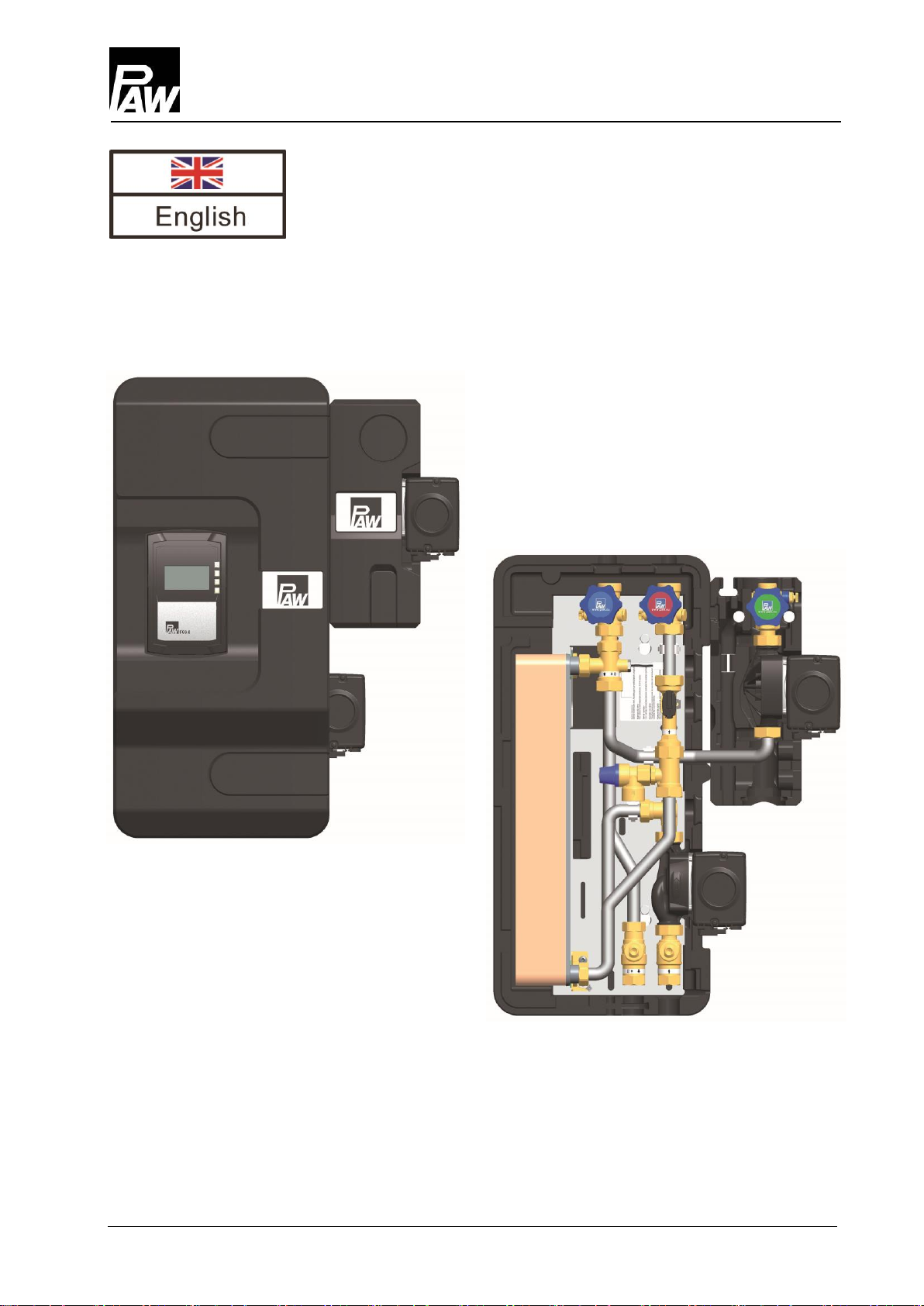
1.2 About this product .......................................................................................................... 5
1.3 Designated use .............................................................................................................. 5
2Safety instructions............................................................................................................... 6
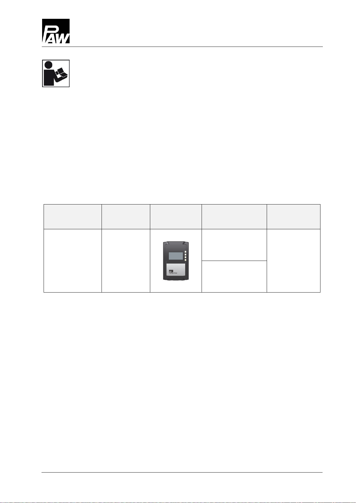
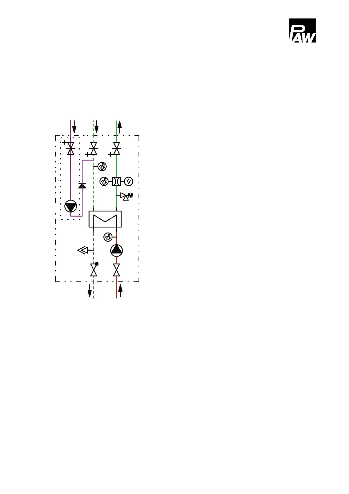
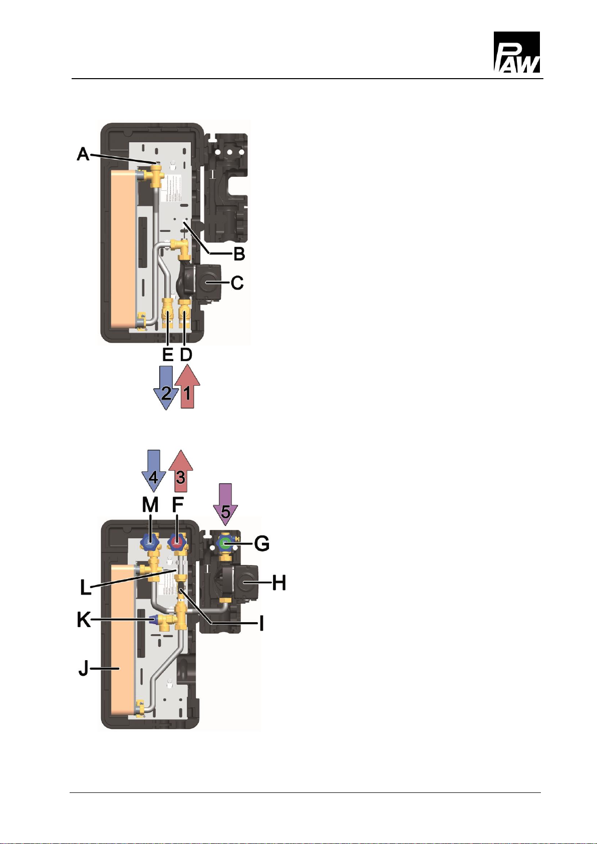
3Product description.............................................................................................................. 7
4Dimensioning and planning ................................................................................................. 8
4.1 Dimensioning of the tank ............................................................................................... 9
5Circulation mode ............................................................................................................... 10
6Assembly and installation [specialist] ................................................................................ 11
7Commissioning [specialist] ................................................................................................ 14
7.1 Filling the primary circuit .............................................................................................. 15
7.2 Commissioning of the controller................................................................................... 16
7.3 Maximum withdrawal flow rate..................................................................................... 18
7.4 Setting the temperature ............................................................................................... 20
8Maintenance [specialist] .................................................................................................... 21
9Spare parts [specialist] ...................................................................................................... 22
9.1 Spare parts primary circuit FriwaMini with circulation (6404631)....................................... 22
9.2 Spare parts primary circuit FriwaMini with circulation (6404631)....................................... 23
10 Technical data................................................................................................................... 24
10.1 Dimensional drawing FriwaMini with circulation........................................................... 25
10.2 Pressure drop characteristics FriwaMini with circulation ............................................. 25
11 Commissioning report ....................................................................................................... 26

1General Information
4 996404631-mub-en - V02 2015/12
1General Information
1.1 Scope of these instructions
These instructions describe the installation, commissioning, function and operation of the
FriwaMini domestic hot water module with circulation. The chapters called [specialist] are
intended for specialists only.
For other components of the system such as tanks, controllers or pumps, please observe the
instructions of the corresponding manufacturer.
Station
Item number
Controller
FC3.8
Pump
prim./sec.
Heat exchanger
FriwaMini
with
circulation
6404631
Prim: Grundfos
UPM2 15-75
30 plates
Sec: Grundfos
UPM2 15-75 CIL2
Carefully read these instructions before installation and commissioning.
Save these instructions in the vicinity of the installation for future reference.

1General Information
2015/12 996404631-mub-en - V02 5
1.2 About this product
The domestic hot water module is a premounted fitting group checked for leakage used to
transfer the heat between the buffer tank and the domestic hot water circuit. It contains a preset
controller as well as important fittings for the operation of the system:
Ball valves in the primary circuit
Piston valves in the secondary circuit
Pressure relief valve in the secondary circuit
Premounted controller
Temperature sensor in the cold water supply
Temperature sensor in the heating circuit flow
line
Flow meter in the domestic hot water outlet
Primary and circulation pump, can be isolated
Manual vent valve for venting the heat
exchanger and the pump
1.3 Designated use
The domestic hot water module must be used in heating installations between the buffer tank
and the domestic hot water circuit. Due to its design the station must be mounted and operated
in a vertical position. The technical data specified in these instructions must be observed.
Only use PAW accessories with the domestic hot water module.
Improper usage excludes any liability claims.
The wrapping materials are made of recyclable materials and can be disposed of with
recyclable materials.

2Safety instructions
6 996404631-mub-en - V02 2015/12
2Safety instructions
The installation and commissioning as well as the connection of electrical components require
technical knowledge commensurate with a recognised vocational qualification as a fitter for
plumbing, heating and air conditioning technology, or a profession requiring a comparable level
of knowledge [specialist]. The following must be observed during installation and
commissioning:
Relevant local and national regulations
Accident prevention regulations of the professional association
Instructions and safety instructions mentioned in this manual
NOTICE
Material damage due to mineral oils!
Mineral oil products cause lasting damage to seals made of EPDM, whereby the sealant
properties are lost. We do not assume liability nor provide warranty for damage to property
resulting from sealants damaged in this way.
It is imperative to avoid that EPDM gets in contact with substances containing mineral
oils.
Use a silicone- or polyalkylene-based lubricant free of mineral oil such as Unisilikon
L250L and Syntheso Glep 1 from Klüber or a silicone spray.
NOTICE
Malfunction!
The domestic hot water module has to be integrated in the potential equalisation of the
electric installation. This can be guaranteed by establishing a potential equalisation
connection to the main potential connection according to regulations or by the connected
pipe system.

3Product description
2015/12 996404631-mub-en - V02 7
3Product description
Primary circuit
Connections
1
Primary side/heating side:
Flow from the buffer tank
2
Primary side/heating side:
Return to the buffer tank
3
Secondary side/DHW side:
Hot water outlet
4
Secondary side/DHW side:
Cold water supply
5
Secondary side/DHW side:
Hot water supply, circulation
Equipment primary circuit
A
Manual vent valve
B
Temperature sensor Pt1000
C
Primary pump
D
Ball valve
E
Ball valve with check valve
Equipment secondary circuit
F
Piston valve with drain valve
(hot water outlet)
G
Piston valve with drain valve (circulation)
H
Circulation pump
I
Analogue flow rate sensor, VFS 2-40 l/min
J
Heat exchanger
K
Pressure relief valve 10 bars
Only for the protection of the module.
Does not replace the pressure relief valve that
has to be mounted on site!
L
Temperature sensor Pt1000
M
Piston valve with drain valve
(cold water inlet)
Secondary circuit

4Dimensioning and planning
8 996404631-mub-en - V02 2015/12
4Dimensioning and planning
The FriwaMini is a domestic hot water module using the principle of a flow-type water heater.
The DHW module will only work flawlessly if the installation meets certain requirements.
Please take some time to plan the installation.
WARNING
Danger of scalding due to hot water!
Undesirable circulation of the water in the primary circuit can cause the exit of hot
water of up to 90 °C at the withdrawal point.
External pumps must not be installed between the domestic hot water
module and the buffer tank.
The domestic hot water module must not be connected to a distribution
manifold.
Mounting example
FriwaMini circulation with optional return distribution (item no. 640425).
Safety group
according to
DIN 1988

4Dimensioning and planning
2015/12 996404631-mub-en - V02 9
4.1 Dimensioning of the tank
The following table helps you to calculate the approximately required volume of the buffer tank.
Temperature in
the buffer tank
Domestic hot water
temperature adjusted
at the controller
Required tank volume
for one litre of warm water
50 °C
45 °C
1.6 litres
60 °C*
45 °C
0.9 litres
50 °C
1.2 litres
55 °C
1.7 litres
70 °C
45 °C
0.7 litres
50 °C
0.9 litres
55 °C
1.1 litres
80 °C
45 °C
0.6 litres
50 °C
0.7 litres
55 °C
0.8 litres
Calculation example for the dimensioning of the buffer tank:
Temperature the buffer tank: 60 °C
Maximal withdrawal quantity needed: 20 l/min
Domestic hot water temperature adjusted at the controller: 45 °C
How large must the tank be to allow for a continuous withdrawal for 20 minutes without
reheating?
20 l/min x 20 min = 400 l
400 l x 0.9 = 360 l
The heated part of the buffer tank must have a volume of 360 litres.

5Circulation mode
10 996404631-mub-en - V02 2015/12
5Circulation mode
The domestic hot water module is equipped with a circulation pump.
Three possible operating modes are stored in the controller for operating the circulation pump
(see controller instructions, page 29 ff).
Pulse-controlled operation (depending on the demand / requirements):
The short opening of a hot water tap (tap pulse: ~2 sec.) starts the circulation pump.
The circulation pump will then run for several minutes (adjustable).
Time-dependant operation:
The operation of the circulation pump can be adjusted within an arbitrary period of time
on a week plan. The circulation will start at the beginning of the period of time chosen.
It will stop after the end of the chosen period of time.
Temperature-dependant operation:
The circulation only starts when the adjustable minimum temperature on the circulation
temperature sensor is exceeded within the period of operation chosen. The circulation
stops after the required temperature has been reached or after the end of the chosen
period of time.
The modes of operation can be combined as required, e.g. time- and temperature-dependant
operation mode. The circulation is only active when the temperature at the circulation
temperature sensor falls below the required value and when the time window is active.
Outside the time window, the circulation pump can be started by a tap pulse when the impulse
driven operation mode is additionally activated.
NOTICE
Damage to property!
When the DHW module is delivered, the circulation is not activated (see controller instructions,
page 29). During commissioning the operation mode must be selected and preset under all
circumstances. The PWM signal must determine the speed of the circulation pump
(factory setting: 100 %).

6Assembly and installation [specialist]
2015/12 996404631-mub-en - V02 11
6Assembly and installation [specialist]
The domestic hot water modules must only be connected with the storage tank by separate
connections for flow and return. External pumps must not be installed between the domestic hot
water module and the buffer tank. The circulation of water causes heavy temperature
fluctutations.
The potable water connection has to be carried out in accordance with the relevant norms (for
example DIN 1988)!
NOTICE
Damage to property!
The pressure relief valve integrated in the station does not replace the safety groups of the
potable water connection as per DIN 1988. The pressure relief valve only protects the module
from overpressures in case of servicing.
NOTICE
Damage to property!
If there are water supplies that may cause pressure surges (for example flush valves, washing
machines or dishwashers), connected to the same mains as the domestic hot water module,
we recommend the installation of water hammer arresters close to the place where these
pressure surges may be caused.
For example make Flexofit S of the Flamco-Flexon company or make reflex of the Winkelmann
+ Pannhoff GmbH company.
DHW
module
fitting
drain valve
pressure relief valve
return valve (non return valve)
pressure reducing valve
test valve
shut-off valve
hot water
cold water

6Assembly and installation [specialist]
12 996404631-mub-en - V02 2015/12
WARNING
Risk to life and limb due to electric shock!
Prior to commencing electrical work on the controller, pull the mains plug!
Only after completing all installation work, plug the mains plug of the
controller into a socket. This avoids an unintentional start of the motors.
NOTICE
Damage to property!
The location of installation must be dry, load-carrying, frost-proof and protected against
ultraviolet radiation to prevent material damage to the installation.
1. Determine the mounting location of the
domestic hot water module near the
buffer tank. The pipes in the heating
circuit must not exceed a length of 4 m
(for DN 20).
2. Copy the measure for the mounting holes
to the mounting surface.
You can find a corresponding drilling
template (see on the right) on the paper
board under the module.
3. Drill the holes and insert appropriate wall
plugs into the holes.
4. Turn the screws into the wall plugs, so
that about 40 mm of each screw still stick
out.
5. Remove the insulating front shell.
6. Hang the module onto the screws.
Tighten the screws, so that the sides of
the insulation are flush to the wall.

6Assembly and installation [specialist]
2015/12 996404631-mub-en - V02 13
7. Connect the domestic hot water module
to the installation according to the figure.
1
Primary side:
flow from the buffer tank,
connection: ¾" internal thread,
pipes: at least DN 20: 22 x 1 mm,
recommended DN 25: 28 x 1.5 mm
2
Primary side:
return to the buffer tank,
connection: ¾" internal thread,
pipes: at least DN 20: 22 x 1 mm,
recommended DN 25: 28 x 1.5 mm
3
Secondary side:
hot water outlet,
connection: ¾" external thread,
flat sealing
4
Secondary side:
cold water supply,
connection: ¾" external thread,
flat-sealing
5
Secondary side:
hot water supply, circulation,
connection: ¾" external thread,
flat sealing
Pipe distance to the wall
(secondary) = 107 mm
Pipe distance to the wall
(primary) = 67 mm

7Commissioning [specialist]
14 996404631-mub-en - V02 2015/12
7Commissioning [specialist]
Note!
Open the valves in the pipes and in the module slowly, to prevent pressure surges.
Function check valve
The primary circuit is equipped with a check valve
in the ball valve (E) to avoid unwanted gravity
circulation.
For venting and flushing the check valve must be
open. Therefore turn the ball valve to the position
45°.
In this position the check valve is not operating.
During operation, all the valves must be completely
open (position 0°).
Position 0°
Position 45°
Position 90°
Check valve is operating,
flow only in flow direction.
Check valve is not operating,
flow in both directions.
Ball valve closed,
no flow.
14

7Commissioning [specialist]
2015/12 996404631-mub-en - V02 15
7.1 Filling the primary circuit
WARNING
Danger of scalding due to hot water!
The system is under pressure. By opening the vent valve hot water with a
temperature of up to 90 °C may exit and cause personal injury.
Open the vent valve slowly and with sufficient distance.
When the storage tank is (partly) filled
1. Slowly open the ball valve (D) by turning it to position
0°.
2. Fill the storage tank using the already existing fill
valve until an operating pressure of about 1.5 bars*
is reached. Use appropriate water according to
VDI 2035 / ÖNorm H5195-1.
3. Manipulate the vent valve (A) cautiously to let the air
escape.
4. Close the vent valve (A).
5. Close the ball valve (D) by turning it to position 90°.
6. Slowly open the ball valve (E) by turning it to position
45°.
7. Manipulate the vent valve (A) cautiously to let the air
escape.
8. Close the vent valve (A).
9. Check the operating pressure after venting and
increase the pressure if necessary.
10. Open the ball valves (D) and (E) completely by
turning them to position 0°.
Primary circuit
*1,5 bars in the primary circuit = recommended minimum value
The pressure depends on the individual system pressures and the components of the heating
installation!

7Commissioning [specialist]
16 996404631-mub-en - V02 2015/12
7.2 Commissioning of the controller
WARNING
Risk to life and limb due to electric shock!
Check if the sensors and the pumps are properly connected to the
controller and if the controller housing is closed.
Only then should the mains plug of the controller be plugged into a socket.
1. Connect the domestic hot water module to
the mains (230 V, 50 Hz) using the
premounted connection cable.
2. Select "Manual mode" in the main menu of
the controller and set the pump to "H1"
(PWM signal = 100 %), see controller
manual page 19.
3. Let the pump run for several minutes to
deaerate the domestic hot water module.
4. When the air noises do not stop, carefully
manipulate the vent valve (A) while the
pump is still running and let the air escape.
5. When the air noises have stopped, switch off
the pump.
6. To do so, select "Manual mode" in the main
menu of the controller and set the pump to
automatic operation ("A").
7. Slowly open the piston valves on the
secondary side (F and M).
Primary circuit
Secondary circuit

7Commissioning [specialist]
2015/12 996404631-mub-en - V02 17
8. Open a withdrawal point for domestic hot
water (for example a tap) with a flow rate of
at least 10 l/min and let the water run for
about 2 minutes to deaerate the secondary
circuit. Then close all withdrawal points in
the secondary circuit.
9. Make sure that the domestic hot water
module is correctly integrated into the
potential equalisation of the installation.
10. Set the desired domestic hot water
temperature in the controller
(see page 24).
11. The domestic hot water module is now ready
for operation.
Secondary circuit

7Commissioning [specialist]
18 996404631-mub-en - V02 2015/12
7.3 Maximum withdrawal flow rate
The following diagram shows the maximum withdrawal flow rate depending on the tank
temperature with a preset hot water temperature of 45 °C at the tap. The integrated control
prevents the temperature from falling as long as the maximum flow rate is not exceeded.
Withdrawal flow rate [l/min]
Power [kW]
Domestic hot water temperature: 45 °C
Boundary conditions: cold water temperature: 10 °C
Max. pressure drop on the domestic hot water side of the DHW module: 1000 mbars
The following examples show the relations between the variables temperature of domestic hot
water, withdrawal flow rate and temperature of the buffer tank and show their effect on the heat
transfer capacity of the DHW module.
Example 1
Domestic hot water temperature at the withdrawal point: 45 °C
Temperature in the buffer tank: 50 °C
DHW module: max. withdrawal flow rate: 17 l/min, heat transfer capacity: 41 kW
Example 2
Domestic hot water temperature at the withdrawal point: 45 °C
Maximum withdrawal flow rate 28 l/min
DHW module: temperature in the buffer tank: 60 °C, heat transfer capacity: 67 kW
FriwaMini with circulation
Temperature of the
buffer tank
Example 2
Example 1

7Commissioning [specialist]
2015/12 996404631-mub-en - V02 19
The following diagram shows the maximum withdrawal flow rate depending on the tank
temperature with a preset hot water temperature of 45 °C at the tap after the addition of cold
water of 10 °C.
The temperature of the domestic hot water adjusted at the controller is 60 °C.
Withdrawal flow rate [l/min]
Power [kW]
Domestic hot water temperature: 45 °C, after heating
to 60 °C and addition of cold water (10 °C)
Boundary conditions: cold water temperature: 10 °C
Example 1
Domestic hot water temperature at the controller: 60 °C
Temperature in the buffer tank: 70 °C
DHW module: max. withdrawal flow rate: 28 l/min, heat transfer capacity: 69 kW
Example 2
Domestic hot water temperature at the controller: 60 °C
Maximum withdrawal flow rate 21 l/min
DHW module: temperature in the buffer tank: ~65 °C, heat transfer capacity: 53 kW
FriwaMini with circulation
Temperature of the
buffer tank
Example 1
Example 2

7Commissioning [specialist]
20 996404631-mub-en - V02 2015/12
7.4 Setting the temperature
Set the desired (maximum) domestic hot water temperature in the controller under "Adj. values /
Nominal temperature" (see controller manual, page 24).
WARNING
Danger of scalding due to hot water!
In order to avoid scalding at the tap, the maximum domestic hot water
temperature adjusted at the controller must not exceed 60 °C.
Primary circuit
The required temperature in the primary circuit in the buffer tank depends on the desired water
temperature and the required tap quantity. The buffer tank temperature must be at least 5 K
above the desired domestic water temperature.
Secondary side
The possible withdrawal flow rate [l/min] at the tap depends on the domestic hot water
temperature adjusted at the controller and the temperature in the buffer tank.
The maximum domestic hot water flow rate through the module is ~38 l/min.
The following table shows the relation between the storage tank temperature and the maximum
withdrawal flow rate with a water temperature of 45 °C at the tap (for example single lever tap).
When the hot water temperature set in the controller is above 45 °C the tap flow rate results
from a mixture of hot and cold water.
The cited heat transfer capacity is necessary to heat up the water to be withdrawn [l/min] from
10 °C to 45 °C.
This manual suits for next models
1
Table of contents
Popular Heat Pump manuals by other brands

Sanyo
Sanyo ECO-i APR-CHP680BA Submittal data

DeLonghi
DeLonghi Bran 0011M H Installation, operating & service instructions

Nortek
Nortek PPH3RF Series installation instructions

Goodman
Goodman SSZ 16 SEER Technical manual

Trane
Trane LIFT 81-P Installation operation & maintenance

evoheat
evoheat CS-i Series Installation & operation manual