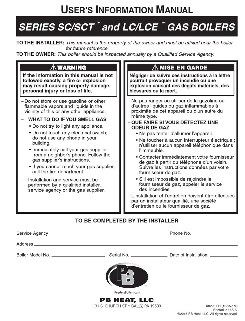
PB Heat TC Series Instruction manual


This manual suits for next models
15
Table of contents
Other PB Heat Boiler manuals
PB Heat
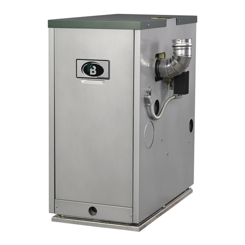
PB Heat PSC-06 Instruction manual
PB Heat
PB Heat mod-u-pak User manual

PB Heat
PB Heat 62-09 Instruction manual
PB Heat
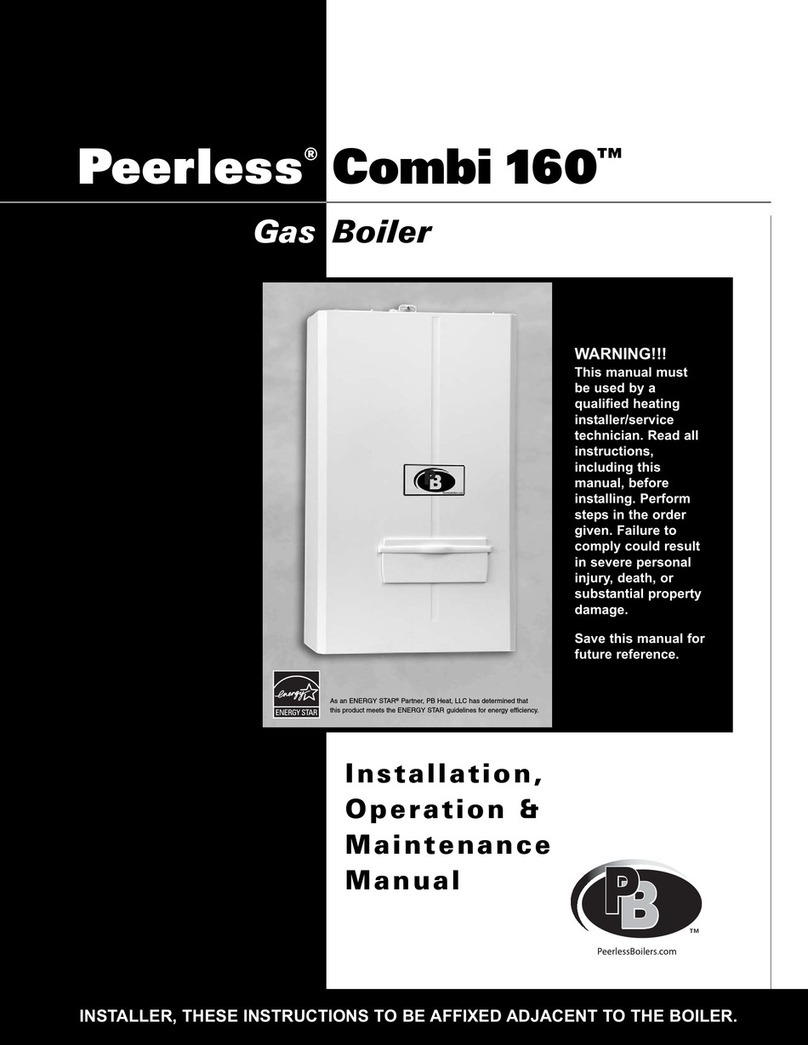
PB Heat Peerless Combi 160 User manual
PB Heat
PB Heat Series GM Guide
PB Heat
PB Heat MI Series Guide

PB Heat
PB Heat SERIES 63 Guide
PB Heat
PB Heat PureFire PFC-625 Guide
PB Heat
PB Heat PSCII SERIES Guide
PB Heat
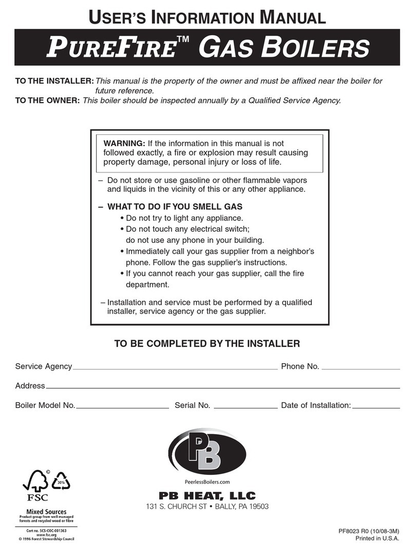
PB Heat PUREFIRE Guide
Popular Boiler manuals by other brands

Radiant
Radiant R1K 75 user manual
Ravenheat
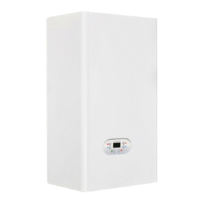
Ravenheat HE 25 C COMPACT Instructions for use installation and servicing
A.O. Smith
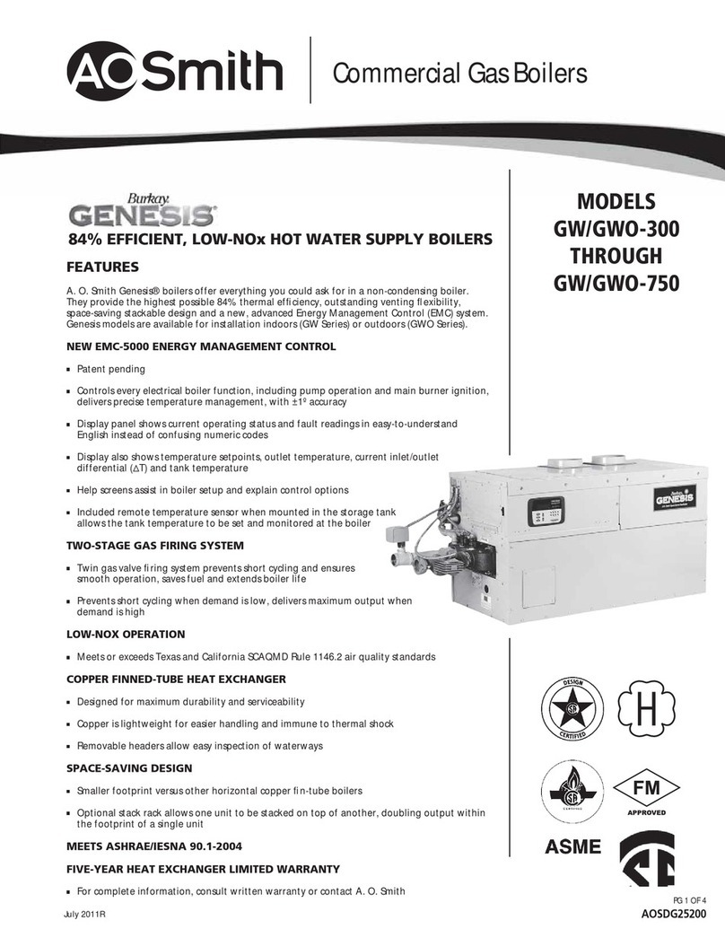
A.O. Smith GW-300 Specification sheet
Granby
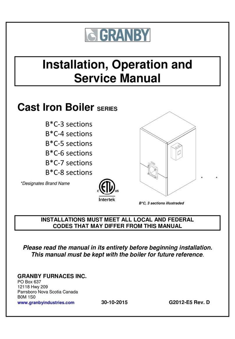
Granby B*C-3 sections Installation, operation and service manual
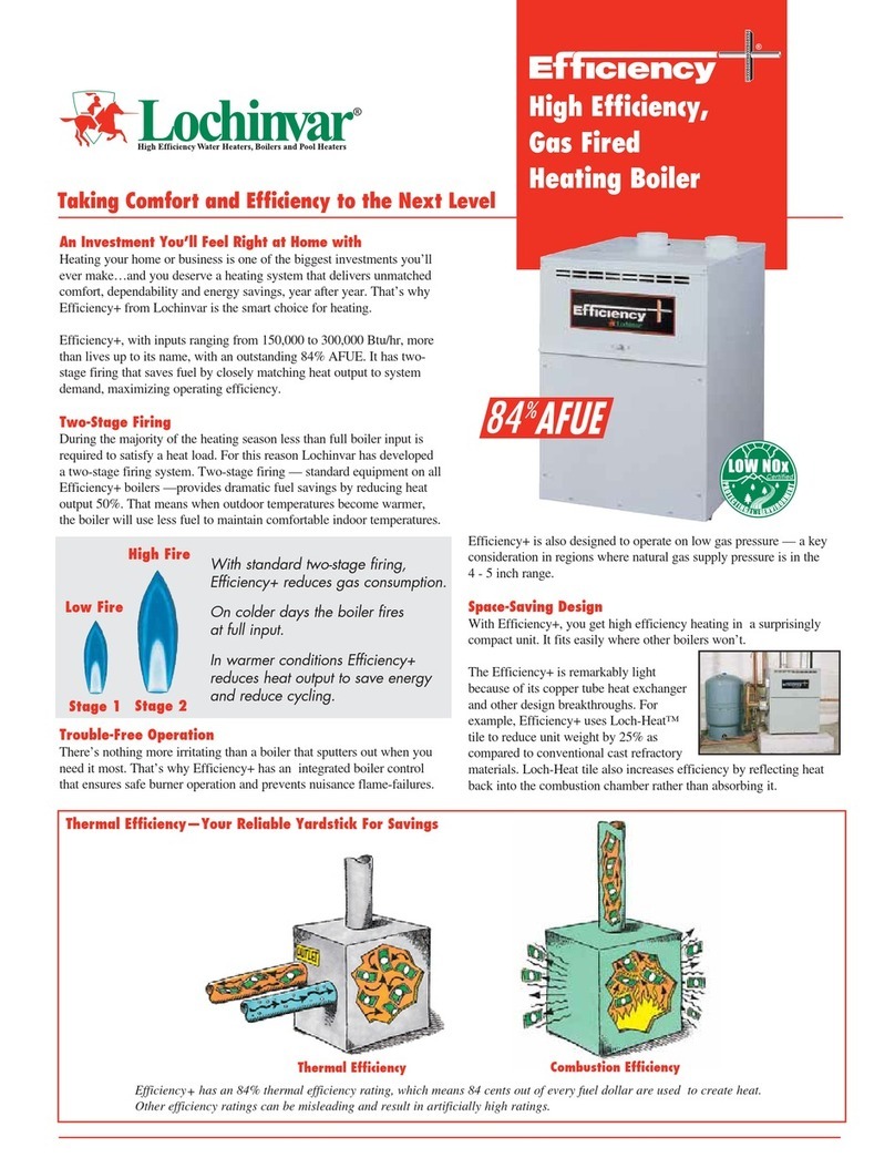
Lochinvar
Lochinvar EFFICIENCY+ E B N 150 Specifications

REMEHA
REMEHA Avanta Plus 28c user guide
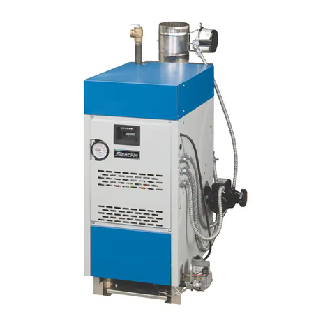
Slant/Fin
Slant/Fin S-150 Installation and operating instructions
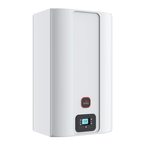
Biasi
Biasi M300V.2025 SM Service manual

Biasi
Biasi RCH 1500 Technical manual

Calomax
Calomax CASCADE-6TC Assembly, installation and operation instructions

Fondital
Fondital ANTEA CONDENSING Installation, use & maintenance manual

Nature's Comfort
Nature's Comfort GT-220 Installation and operating instructions
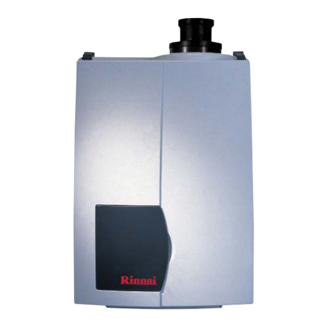
Rinnai
Rinnai E50C Installation & servicing instructions

Potterton
Potterton 360 Erection installation, commissioning & servicing instructions
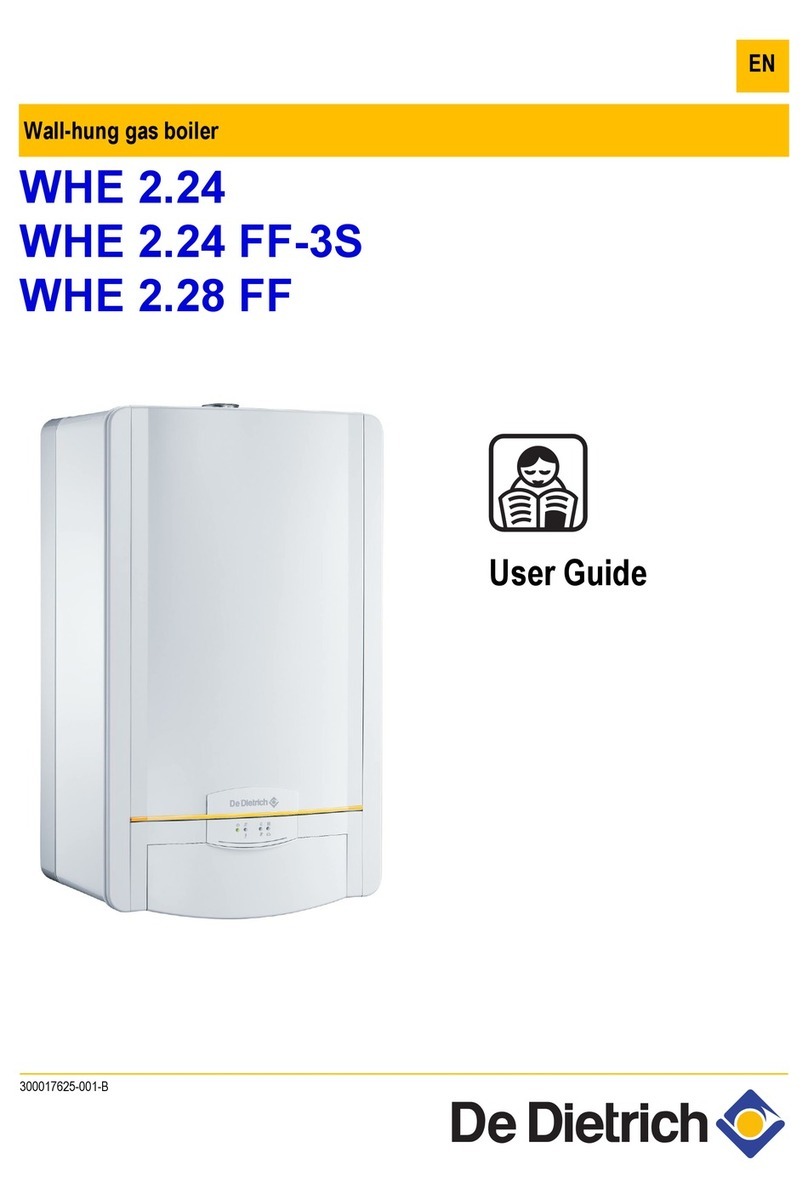
DeDietrich
DeDietrich WHE 2.24 FF-3S user guide

Westinghouse
Westinghouse WBRC 140F Series Installation & start-up instructions
Myson
Myson Apollo 30Si Installation and servicing instructions
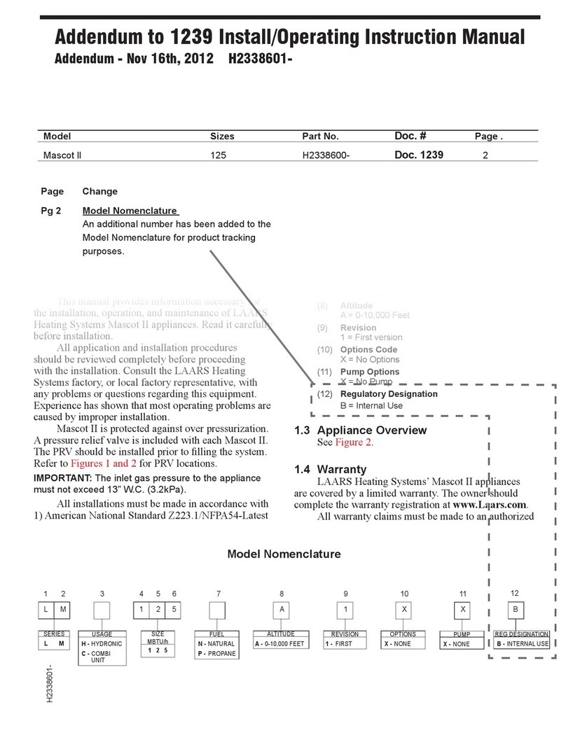
Laars
Laars LMH user manual
