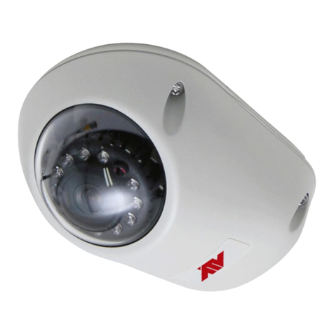
pbq SEE-PTZ600 Series User manual

Installation and Operation Manual
SEE-PTZ600 series
SEE-PTZ605 Iridium Silver / SEE-PTZ608 Ivory
HIGH Speed PTZ Dome with 3 alarm inputs
PTZ600
SERIES
Optical
Zoom
Total
Zoom
Day/Night
IR
Sensitive
Minimum
Lux
Nite
Devil
Focal Length
Option M
30x
360x
YES
YES
0.01 LUX
YES
4.5 ~ 135mm
Option L
23x
276x
YES
YES
0.01 LUX
YES
4.0 ~ 92mm
Version 1 Last Revised 05/09/2016
the HD-TVI PTZ range

Last Revised 05/09/2016
2
CONTENTS TABLE
Description Page No.
Contents 2
Safety Precautions 3
Description of Functions 4
Special Dome Features –3 channel alarm input activation –Modify Dome address by RS485 5
Getting the PTZ up & running 6
Overview –introduction to fitting PTZ equipment 6
Coaxitron and RS485 8
RS485 Wiring methods & Tips 9
Setting up the Dome Camera 12
RS485 connection –Connecting the Keypad or DVR to the Dome 13
Coaxitron 15
Connecting the video out of the dome 15
If you are using more than one dome on a site 17
Setting up a unique address in a dome 17
Setup of the Protocol and the Default Baud Rate 18
Using the PTZ735 keypad with the PTZ600 series 20
Presets and other functions 21
Patrols (Tours) –How to set them up and use them 22
Auto Scan –How to set it up –Calling theAuto Scan 24
Record Pattern –What is a record pattern? 25
What is the difference between a pattern & a patrol (tour)? 25
How to set it up –Running the Record Pattern 26
Using the M camera module 27
Schedule What is it ? - How to set it up - How to set Schedule –Special Tips 28
Using the Dome’s Advanced Functions 31
Using the Menu System 32
System Setup 33
Display Setup 34
Camera Setup 35
Motion Setup –Presets-Auto Scan - Patrols (Tours) –Patterns –Schedule - Clear 37
Privacy Mask - Using onAlien DVR 41
Advance Setup –Home Setup –Password –CAM ID Setup –Fan Control 42
Advance Setup –Time Set - More - Shortcut Function for M module commands 46
System Reset - Exit 47
Using the M camera module 48
Controlling one camera then another 49
System Installation 50
Alarm Input cable connections 57
3 Channel alarm input activation & single channel alarm output 58
Connecting the InputAlarm devices 58
Connecting the Output Alarm 59
Technical Specification 60
AppendixA: Lightning Proof and Surge Signal Proof 61
Appendix B: General Information –The Cleaning of Dome Cover/Troubleshooting 62

Last Revised 05/09/2016
3
Please read this operation manual carefully
before installing and using this unit !!!!
Please read the following;
1. Please read the operation manual carefully before installing and operating the product.
2. The actual dome requires a 24v AC power supply. The rated input voltage of the camera is 12V!!!! This
gets its power from the dome and does not require a separate PSU. Do not connect 24VAC to the camera
under any circumstances!!
3. During the course of transportation, storage and installation, the product should be handled with care
avoiding vibration and any weight pressure, which may cause damage to the sophisticated optical and
electronic equipment inside the machine.
4. Do not attempt to disassemble the camera. In order to prevent electric shock, do not remove screws or
covers. There are no user-serviceable parts inside the camera.
5. Always use and stick to current electrical safety standards to install and use the dome. Use a correctly
rated power supply. The RS-485 and video signal cables should be kept way from other high voltage
equipment such as mains cables and especially fluorescent lights. Using an anti surge protection device
is recommended to prevent damage to the domes from lightning and mains surges. Damage to domes by
lightning or mains voltage surges is not covered under the domes warranty.
6. Do not operate in areas exceeding the stipulated limitations concerning temperature, humidity and power
supply.
7. Do not aim the camera directly towards the sun or an extreme light source whether it is switched on or
not. Do not let the camera focus on bright and stationery objects for a long time. Doing either of these
may damage the camera.
8. Do not use strong detergents to clean the main body of the camera as these may damage the dome cover
or paintwork. Wipe dirt with dry cloth. If needed a mild detergent can be used.
9. Operate the dome camera with great care to avoid shock or vibration. If operated incorrectly, the Dome
could be damaged.
10. Ensure the dome is not dropped. Never mount the unit on a ceiling that cannot support its weight.
11. If necessary, use a commercial lens cleaning paper to clear the lens windows. Gently wipe the lens window
until clean.

Last Revised 05/09/2016
4
Description of Functions
This intelligent dome camera is a hi-tech CCTV product, which incorporates a high-clarity colour
camera. It has a panoramic variable speed PAN/TILT movement, a multifunctional decoder, a
character generator and an on-board processor for logic handling. The dome is easy to connect,
install, maintain and operate, and has many features. The dome is compact and has a strong
structure with a modern and appealing appearance.
1. Integrated Multi-Protocol Decoder
a. The integrated multifunctional decoder can communicate with 16 different protocols. The
baud rate can be independently set allowing compatibility with numerous systems with
selectable baud rates from 2400 bps to 19200 bps. Dip switches control the selection of the
protocol and baud rate thus making this dome camera easy to set up and use.
b. This dome uses RS485 serial control and can address from 1 to 1023 cameras using binary
addresses.
2. Integrated Speed-Variable PAN/TILT
a. The dome can turn 360ºhorizontally and continuously with unlimited positions with an
adjustable speed from 0.2° ~ 300° per second and turning 0º~ 90° vertically with a manual
speed from 0°~ 120° per second.
b. The dome can run at low speed, low noise, and does not show any picture shake.
c. The dome has an automatic 180ºflip facility and provides panoramic monitoring without
any blind spots.
d. This dome is a high precision unit and maintains preset positions up to ±0.1°.
3. High Intelligent Settings
a This dome can store up to 128 preset positions in non-volatile memory that are not lost
with a power failure. Refer to the section “Presets and other functions.”
b The dome can scan horizontally between two points and the scan speed can be modified.
The dome can scan a range larger or smaller than 180° between any two points with
adjustable speed settings. A total of 3 scans can be stored. Refer to the section on “Auto
Scan.”
c Six sets of tours (patrols) each with 16 preset positions can be programmed. The run
speed is adjustable and a schedule available for timed functionality. Refer to the section
on “Patrols (Tours).”
d. The dome camera can simulate a route operated by you within a 120 second interval by
utilising the Record Pattern facility. A total of 3 patterns can be stored. Refer to the
section on “Record Pattern.”
e. Proportional pan function. The dome travel speed will depend upon the extent of the
zoom coverage. In telephoto zoom mode, the pan and tilt speeds will be slower for a
given amount of joystick movement than that in wide zoom mode. This keeps the image
from moving too fast on the monitor when there is a large amount of zoom coverage. This
slowing down does not occur when going to a preset, but does occur in turbo mode when
the high speed zoom is selected. The minimum pan and tilt speeds are 0.1 degree per
second at full zoom.
f. Password Function. Allows access to the menu to be password protected. Default =
111111
g. Angle Display. Three options for displaying camera angle settings.
KEY FUNCTIONS

Last Revised 05/09/2016
5
h. Software Modify the Dome Address. Allows dome address to be changed through RS485
software (SID).
i. Image Effect & Zero Iluminance. Will display when set in B&W mode or manual zero
illuminance.
j. Angle Display. The dome can display panning, tilt and view angles of the camera.
4. NiteDevil Feature
a. The M camera module incorporates a (SL) slower shutter speed allowing the camera to see
more at low light levels. This camera option is best suited to slow moving scenes or
stationary scenes. The module has 30x optical zoom, resolution of 1080P and 4.5 -135mm
2MP varifocal lens. Illumination is at 0.01 Lux.
NOTE that the M module is integrated into the PTZ menu functionality and therefore
does not have a separate camera module menu.
5. Special Dome Features
3 channel alarm input activation & single channel alarm output
One of the special features of this dome is that it has three in-built alarm channels to call
three independent presets. This means that for example you may have a door contact and
when the contact is closed, it sends a 0 volt alarm switch to the dome on one of the three
alarm channels. The dome will then call a previously set preset position and lock the camera
onto that position. A single channel alarm out, allows the connection of an audible alarm,
lighting or other warning device. When more than one alarm input channel is utilised and
activated, the dome will switch to the next channel after two seconds. However once an
alarm input channel has been activated, the dome will remain locked to the preset position/s
and will not resume a patrol, auto scan or a record pattern until the alarm condition is
cleared. However the ALARM SETUP options in the dome SYSTEM SETUP menu can be
set to return to a home position if necessary. Three alarm channels can call preset positions 1
~ 50. For example:
Alarm channel 1 could call preset number 10 - Alarm channel 2 preset number 12
Alarm channel 3 preset number 31.
Refer to the instructions under “Physical installation of the dome” for the wiring diagram.
Modify DomeAddress by RS485
The Hardware ID (HID) address is set by the dipswitch settings but can be modified bysetting the
Software ID (SID) address via the menu. The SID is retained over power down. If the HID is
altered e.g HID = 003, theSID will also change to 003.
Scheduling Functionality
This PTZ camera incorporates a schedule for editing automatically operations during different
time periods. Up to 8 periods per day can be set to run different operations such as moving to
preset positions, running different tours, patterns or scans.
Display Options
APTZ name and/or dome temperature can be displayed in in the PTZ dome menu.

Last Revised 05/09/2016
6
Getting the PTZ up and running!
You MUST connect up the PTZ and your control equipment on a workbench or kitchen table before the
actual site installation and CHECK YOU KNOW HOW TO INSTALL IT CORRECTLY!!!!!!!!!!!!!!!!!.
By doing this you can set-up any DIP switches, adjust the camera, and learn about how it operates before
taking it to site. This will save you hours of time on-site trying to work out why a particular item doesn’t
function as you expected it to. There is nothing worse than installing something and then having to take it
down to see how to get it working!! Do the learning curve in the comfort of your own premises!!!!
Overview- introduction to fitting PTZ equipment
Generally speaking, PTZs require four things;
1- They require a power supply and a cable to supply this power to the PTZ. The PTZ600 series
operates on 24VA.C.
2- They require a cable to get the video signal back to the monitor or recording device.
3- They require a cable to transmit the “RS485 control signal” from the keypad or DVR to tell the
PTZ to pan and tilt etc.
4- Alternatively you can control a TVI PTZ using the DVR, by using the coaxitron option through
the video cable.
The following diagram indicates the basic cable requirements for a PTZ system.
Do you KNOW how to install PTZ equipment that is
controlled by RS485 data signals or via Coaxitron?
If not please read the following introduction to PTZ >>>….

Last Revised 05/09/2016
7
You can get “composite” cables that will carry both the power and the video
signals and this has the benefit of combining two of the three cables into one.
You may choose to power the PTZ locally to it, so you may only need to get
the video signal back from the PTZ and the RS485 control signals to it. If this
is the case you may choose to use a pair of HD TVI BALUNS. By using baluns you can send the video
signal and control signal down the same CAT5 cable just using different cores for each signal.
The data signal (RS485) is nearly always sent along a “twisted-pair” type cable. The twists in the cable help
prevent interference affecting the data signal by “shielding” it. Many installation companies use a CAT5 type
or similar cable to run out to the PTZs to carry the data signal. Baluns are not needed for data.
If you are considering using TVI Baluns please note - DVR’s tend to require good video signals to function
correctly and will work up to 200 metres on HD. Note there are no active HD baluns available currently. If
there is a longer distance needed then standard co-ax cable, shotgun or Combo cable will give up to 500
metres for HD video, but this does not apply to power.
You can mix and match how you wire up your PTZ installation and the following general diagram gives you
a guideline about how to do it. Remember this is a GUIDE and is not an instruction what to fit!
Equipment
Cable Needed
Dome
1. Data signal
CAT5 cable
You can also send the video signal
back along a second pair in a CAT5
cable using baluns. Note you cannot
send 24v AC power down CAT5.
2. Video signal
RG59 or similar
You can combine both the video
and power into one cable if you
wish using composite cable.
3. Power
Two core cable capable of carrying at least
2Amp @ 24V AC.
Keypad or
DVR
Monitor
Power Supply
24V AC
Out
Display Equipment
Control Equipment

Last Revised 05/09/2016
8
Coaxitron and RS485
These HD TVI PTZ cameras have telemetry control through either the RS485 cable or up the co-ax using the
coaxitron facility. The benefit of using coaxitron is that there is no need for an RS485 connection. However PTZ
control must be via the DVR and the AlienTVI(Coaxitron) option selected for the relevant camera set in the PTZ
menu settings.
If there is a requirement to use a keyboard, the keyboard must be connected via RS485 so the PTZ menu settings
must be set with the standard RS485 protocol, baud rate and ID as set in the camera rather than the coaxitron
method.
When using the PTZ790 keyboard rather than a standard PTZ keyboard you can use the coaxitron facility via the
DVR mode. However you first need to setup the RS485 settings in the DVR PTZ menu ensuring that the baud rate
is protocol PELCO-D, baud rate 9600 and ID 01 and save and reboot DVR. Then change the protocol to
AlienTVI(Coaxitron) and reboot DVR again.
Many installation companies can get the power and video signal correct, but struggle with the control of the PTZ
using the keypad or DVR using the RS485 data.
The key to successfully installing the data cabling to the PTZ is to get the basics right. Use a quality data cable
such as CAT5 (never use just a standard untwisted cable such as alarm cable for the RS485 signal).
Also, you must follow the RS485 wiring convention; the following section explains this:
BALUN
BALU
N
PTZ
DOME
24V24VA
C AC
LOCAL
PSU
240V ---
CAT 5
CAT5 Carries
Video &
Control Data
CCT CAMERA
Video
& Power
TRADITIONAL
CAMERA
JUNCTION BOXES
PSU
12V
DC
240V
AC
Free Lead Supplied
KEYPAD
DVR
CO-AX RG59
MONITOR
PTZ
DOME
RG59+2 Video & Power
CAT5 Carrying Data
CAT5 Carries Video & Power
RG59+2 Carries
BALUN
BALUN
24V AC

Last Revised 05/09/2016
9
RS485 Wiring methods & Tips >>>>>
1. Characteristics of RS485
As specified by RS485 standards, RS485 is a half-duplex data transmission type with characteristic
impedance of 120Ω. The maximum load capacity is 32 units (domes, keyboards and DVRs).
2. Transmission distances of RS485 Signals using CAT5 or similar cables
Selecting a CAT5 or similar sized twisted pair data transmission cable, the maximum theoretical transmitting
distances are as follows:
Baud Rate
Maximum Transmitting Distance
2400 Bps (PELCO-D)
1500m
4800 bps
1000m
9600 bps
600m
PLEASE NOTE - Using inferior cables, or installing the dome in an environment with strong
electromagnetic interference, or connecting a lot of PTZ domes to the same cable carrying the RS485 signal
will reduce the maximum transmitting distance.
3. RS485 Connection methods
METHOD 1 –DAISY CHAIN CONNECTION.
The general RS485 standard recommends a “daisy chain” connection of equipment that is to be
controlled. This means that the control cable is looped out of the one dome to the next dome and so on.
The last dome in the line is then fitted with what is known as a “termination resistor”. This has a value
of 120Ω.
The resistor is built in the PTZ domes and is activated by moving the appropriate “jumper” in the
dome. The keyboard itself generally has a built-in 120Ωresistor. These termination resistors help make
the signal more stable and give the system better reliability so the domes function as expected. A
common mistake installer’s make is not making sure the 120Ωresistor is switched ON in the LAST
dome. Also installers often select the resistor to ON in another dome in the chain, these errors will
make control of the dome unpredictable.
A simplified Daisy chain is shown below;
This first diagram shows the cables looping in one dome and out of another;

Last Revised 05/09/2016
10
120Ω120Ω
1# 2# 3# 4# 32#
. . . . .
Standard Daisy-Chain connection for the RS485 PTZ control signal
(just the last dome only has the 120Ωresistor set to on, the first device is the keyboard and has the 120Ωbuilt in as default)
This next diagram is a slight variation on the Daisy Chain arrangement. Again it’s one cable going out to all
the domes but instead of the cable going into each dome then back out to the next one, a junction box is used
to “Spur-Off” to each dome. Whilst this can be done THE SPUR LENGTH (D) must be NO MORE THAN
10 metres!!!!!!!!!!!! The overall cable length between the Controller and the last dome is limited to around
300 metres in such an arrangement.
120Ω
1# 2# 3# 31#
120Ω
D
A+
B-
A+ B-
.....
.....
M ain controller
Daisy-Chain connection WITH SHORT SPURS for the RS485 PTZ control signal
(one main radial with very short spurs to each dome off it, keeping the spurs to less than 10 meters)
TIP - The connection of a 120Ωtermination resistor: The termination resistor is ready fitted on the
domes pcb, all you have to do set it is move the jumper from Pins 2 &3 to pins 1 & 2.

Last Revised 05/09/2016
11
STAR method of connection.
In some circumstances you may need to adopt a star configuration for practical purposes. For instance, all the
domes may be so scattered on a large site that running out separate spurs to each dome in a “STAR” array is
the only practical solution.
So how do you do this in practice?
The termination resistors must be connected to the two domes that are farthest away from each other,
such as domes 3 and 5 in the following “Star diagram”. Note that all the other domes do not have the
120ohm resistor connected. The resistors are already fitted to the domes PCB but by default are not in
circuit. To put them in circuit you must move the small “jumper” as previously indicated.
As the star configuration is not in conformity with the requirements of RS485 standards, problems such as
signal reflections may arise, especially when there are long cable connections. The results are that control
signals are decreased and the dome may not respond to, or just responds intermittently to the controller.
If your STAR circuit is not too extensive
with each spur in the region of 20-50 metres
you can expect quite good reliable
performance using this technique. If you
experience any problems though, consider
fitting an RS485 distribution box.
In the real world not everything always works exactly as it’s expected to!
RS485 data signals that control the domes’ movements are tiny signals that can get corrupted for many
reasons. Poor cable quality, not using a PAIR of cores from a CAT5 but using one core from TWO separate
pairs, running the CAT5 cable near mains equipment such as fluorescent lighting all will have a detrimental
effect on the signal. These are things that you can correct with good installation practices.
The Star circuit for wiring PTZ’s.
The two furthest domes need the 120ohm
resistors enabling, by moving the “Jumper”
In this example it’s domes 3 &5.
The Star Diagram

Last Revised 05/09/2016
12
Setting up the Dome Camera
1. Connection of the System
There are many ways to wire up a PTZ system.
If you have read the introduction at the beginning of these instructions you should have got a good idea what
your options are.
Below is a general schematic diagram showing you some of these options.
Powering the domes-
All the domes will need power. For this dome it is a 24V A.C power supply. The power supply must be
capable of delivering at least 800mA per dome in normal conditions but it is advisable to allow some extra
headroom so that the psu is not running flat out. It is therefore recommended to use a 24V~30V AC 1.7A
PSU (POW999).
You can either power each dome with its own PSU locally to it or have the PSU’s remotely situated perhaps
near the keyboard or DVR. The domes require a current of about 950mA when the heater is on and you
must take this into consideration when working out maximum cable runs.
Never put power on CAT5, use the CAT5 + 2. The power cable on CAT5+2 or RG59 + 2 should work up to
80 metres and the Combo power up to 100 metres but in cold weather this will reduce to 70 metres and 90
metres respectively when the PTZ heater kicks in. Otherwise you will need to calculate the correct cable core
size for power on longer runs.
BALUN
BALU
N
PTZ
DOME
24V AC
LOCAL
PSU
240V ---
CAT 5
CAT5 Carries
Video &
Control Data
CCT CAMERA
Video
& Power
TRADITIONAL
CAMERA
JUNCTION BOX
PSU
12V
DC
240V
AC
Free Lead Supplied
KEYPAD
DVR
CO-AX RG59
MONITOR
PTZ
DOME
RG59+2 Video & Power
CAT5 Carrying Data
CAT5 Carries Video & Power
RG59+2 Carries
BALUN
BALUN

Last Revised 05/09/2016
13
Please note - The domes heater doesn’t come on until it senses the temperature drops below 0 degrees
Celsius. At this point the dome will need up to 1A @ 24V A.C to operate. Please make sure that you have a
sufficient power supply and cable installed to cope with this. Obviously the dome may work okay in the
summer but when winter kicks in and the dome’s current draw jumps from 800mA to 950mA, an inadequate
power supply or a cable with too much voltage drop may stop the dome from working properly. When winter
comes don’t be suddenly caught off guard when your customer rings you to say the dome has suddenly
packed in because it’s gone cold!!
A popular way to power the domes is using our COMPOSITE VIDEO cable (or
shotgun as its also known) as this cable can carry the power to the dome and the video
signal back to the monitor or DVR. Alternatively the COMBO cable also
provides the additional RS485 data cable.
The power connection
The RED & BLACK cable coming out of the dome connected to the RED terminal block are for power.
Connect a suitable 24VA.C power supply to this pair of cores.
The two BNC connectors are for HD and Analogue video outputs. Refer to the label on the outside of the
multicore cable for the correct colours either yellow or black to use. The VIDEO-OUT from the camera goes
to the monitor or “VIDEO-IN” of a DVR camera input.
The Orange and Yellow pair of cores that go in to the BLACK terminal block are the data cables. These are
the cores that carry the RS485 control signal to the dome from either the keyboard or the DVR. The next
section of the instructions gives more detail on how to connect the RS485 data. Please also read the RS485
WIRING METHODS & TIPS section towards the beginning of these instructions.
Power cable requirement –Assuming a starting voltage of 24VA.C is applied at the PSU end.
Composite cable Heater OFF Heater ON
Maximum run 80mtr 70mtr
The distances are relatively short due to the high load of the dome when it starts up. If the voltage of the
dome drops below around 20V A.C it will fail to initialise. Obviously you can power the domes locally if
you wish.
RS485 connection - Connecting the Keypad or DVR to the Dome.
There are two methods for controlling the PTZ, either by Coaxitron via the DVR or
via the conventional RS485 using a PTZ keyboard. If you want to control via the
keyboard, RS485 is the best option but you could use the PTZ790 keyboard that
allows control through the DVR menu. Whilst this is feasible operations are more
difficult as there are more layers of commands to enter.
This section details the RS485 method. The RS485 data signal tells the dome to pan, tilt, zoom etc. Its
important that you read the early section of these instructions to understand the fundamental principle of
RS485 cabling techniques so that you get it right.
RS485 has two cores, A and B or sometimes known as RS485 + (A) and RS485 –(B) if you get these two
the wrong away around then you will not be able to control the dome. Sometimes installers get the
connections right on one dome but not on the other and find only one dome works. They then swap the wires
around at the keyboard only to find out one dome has now burst in to life and the other one now failed!!

Last Revised 05/09/2016
14
They don’t just put 2 + 2 together and realise their mistake that they have wired one dome different to the
other. Take great care getting these the right way around and make sure you wire each dome IDENTICALLY
so that if you have to swap theA& B lines over at the keyboard you know all domes are wired the same!!
The PTZ600 series adopts the following RS485
convention:
ORANGE = RS485 + or A
YELLOW = RS485 –or B
You should initially be wiring the dome to the keyboard or DVR on your workshop bench or at least your
kitchen table to prove you know how to get everything to work. Once you have done this, it is just a job of
extending the cables and physically installing the domes on site. You must obviously take note of the RS485
wiring techniques mentioned at the beginning of these instructions and get the 120ohm resistors correct in
the “End of line” domes. Generally speaking you will always be extending the RS485 signal from either the
keypad or the dome using a CAT5 or similar cable. Note that data cables are not connected through
baluns.
If you use cores from two different pairs in the CAT5 cable you will not get the benefit of the shielding effect
of the cable twists and the dome will function erratically. You must always use a core from a PAIR, not two
cores from two different pairs!!
The PTZ735 is one of the keypads that can be used with the
PTZ600 range. On the rear of the keypad you will see the
RS485 connections. Ensure they are connected correctly i.e
the RS485 + Ta line and the RS485 –Tb line as per 1 below.
PTZ735
keypad

Last Revised 05/09/2016
15
Coaxitron –Accessing the PTZ menu and control via the video cable
These HD TVI PTZ cameras have telemetry control through either the RS485 cable or up the co-ax using the
coaxitron facility. The benefit of using coaxitron is that there is no need for an RS485 connection. However
PTZ control must be via the DVR and the AlienTVI(Coaxitron) option selected for the relevant camera set in
the PTZ menu settings. Coaxitron will also work with CAT5.
If there is a requirement to use a keyboard, the keyboard must be connected via RS485 so the PTZ menu
settings must be set with the standard RS485 protocol, baud rate and ID as set in the camera rather than the
coaxitron method.
When using the PTZ790 rather than a standard PTZ keyboard you can use the coaxitron facility via the DVR
mode. However you first need to setup the RS485 settings in the DVR PTZ menu ensuring that the baud rate
is protocol PELCO-D, baud rate 9600 and ID 01 and save and reboot DVR. Then change the protocol to
AlienTVI(Coaxitron) and reboot DVR again.
Connecting the video out of the dome.
The PTZ dome has a multi-core lead of which there are two short BNC leads attached. One has a
thick yellow cable and one a thick black cable. A label is attached to the multi-core lead and this
details whether the BNC is TVI or CVBS (analogue). You need to extend this lead to the “VIDEO-
IN” of the DVR or monitor. Use a good quality RG59 coax cable or similar to do this.
TIP –If you can’t get a picture at the remote end you could always take your test monitor to your
PTZ dome and check the picture quality on its own short BNC lead.
If you’re testing the equipment on a workbench you now have a one dome system. For setting up
the keyboard and testing the dome please read sections on default Dome settings and using the
keyboard.
You can use a keyboard or a suitable DVR to control the dome. A suitable DVR would be one with
PTZ functionality built into it and preferably PELCO-D protocol. If your DVR has a list of
protocols it’s always best to try PELCO-D first. In the DVR, with PELCO-D set, you should also
make sure you set up the baud-rate to 2400.
A typical site installation would look like the following diagram on the next page.
It shows the dome connected to the keypad plus how the dome could also be connected to a DVR
instead of the keypad or at the same time. DVR’s that have the capabilities of PTZ control will have
a terminal or connection on them somewhere, where the dome’s RS485+ A and RS485- B line can
connect to. Please refer to the individual DVR instructions of how to do this.

Last Revised 05/09/2016
16
Note that if the DVR has Coaxitron set in the PTZ menu settings, you can use this rather than the
RS485 connections shown above. You will need to control the PTZ through the Alien DVR menu.
24V AC
INPUT
RS485
+ ‘A’
ORANGE
RS485
- ‘B’
YELLOW
RS485 INPUT ON
DVR
PSU
CAT5 Data cable
RG59 Video Cable
Power Cable

Last Revised 05/09/2016
17
If you’re using more than one dome on a site
Each dome has a unique “address” so that if you are using more than one on a site the keyboard “talks” to the
right dome when you want it to PTZ. If you only have the one dome on the site then the default “address” of
“1” is okay and you have no reason to change the dome from this.
With multiple dome sites you need to set up
each dome address separately. The following
diagram shows the switch options. SW2
sets up the protocol. This switch is dealt with
later in these instructions.
For most System Q equipment they should always be set to PELCO-D 2400 baud rate. In the diagram this is
correct. The Jumper on the far right either enables or disables the 120ohm resistor.
Setting up a unique ADDRESS in a dome –
SW1 is used to set address of the dome camera from 1 –1023.
To set the dome address at 1 put switch 1 up.
To set the dome at address 2 put switch 2 up
To set the dome at address 3 put switches 1 and 2 up.
..and so on..
Special Note:
The jumper and dipswitches are located on the top of
the dome head. To access them push the dome module
up and twist to release and you will see the switches as
per diagram below.

Last Revised 05/09/2016
18
Dome
Address
ID-CODE Status
DIP-1
DIP-2
DIP-3
DIP-4
DIP-5
DIP-6
DIP-7
DIP-8
DIP-9
DIP-10
1
ON
OFF
OFF
OFF
OFF
OFF
OFF
OFF
OFF
OFF
2
OFF
ON
OFF
OFF
OFF
OFF
OFF
OFF
OFF
OFF
3
ON
ON
OFF
OFF
OFF
OFF
OFF
OFF
OFF
OFF
4
OFF
OFF
ON
OFF
OFF
OFF
OFF
OFF
OFF
OFF
5
ON
OFF
ON
OFF
OFF
OFF
OFF
OFF
OFF
OFF
6
OFF
ON
ON
OFF
OFF
OFF
OFF
OFF
OFF
OFF
7
ON
ON
ON
OFF
OFF
OFF
OFF
OFF
OFF
OFF
8
OFF
OFF
OFF
ON
OFF
OFF
OFF
OFF
OFF
OFF
9
ON
OFF
OFF
ON
OFF
OFF
OFF
OFF
OFF
OFF
10
OFF
ON
OFF
ON
OFF
OFF
OFF
OFF
OFF
OFF
11
ON
ON
OFF
ON
OFF
OFF
OFF
OFF
OFF
OFF
12
OFF
OFF
ON
ON
OFF
OFF
OFF
OFF
OFF
OFF
13
ON
OFF
ON
ON
OFF
OFF
OFF
OFF
OFF
OFF
14
OFF
ON
ON
ON
OFF
OFF
OFF
OFF
OFF
OFF
15
ON
ON
ON
ON
OFF
OFF
OFF
OFF
OFF
OFF
16
OFF
OFF
OFF
OFF
ON
OFF
OFF
OFF
OFF
OFF
17
ON
OFF
OFF
OFF
ON
OFF
OFF
OFF
OFF
OFF
18
OFF
ON
OFF
OFF
ON
OFF
OFF
OFF
OFF
OFF
…
…
…
…
…
…
…
…
…
…
…
1023
ON
ON
ON
ON
ON
ON
ON
ON
ON
ON
Table 1
2. Setup of the Protocol and the Default Baud Rate.
As shown in Table 2, SW2 is used to set the protocol of communication and the baud rate used by
the dome camera. DIP-4 to DIP-1 of SW2 is used to select protocols and a maximum of 16 different
protocols can be selected.
PELCO-P/D and 2400 baud rate are generally used in the SEE-PTZ600 systems.
Protocols
DIP status
Normal Baud Rate
DIP-1
DIP-2
DIP-3
DIP-4
DIP-5
DIP-6
B01
ON
OFF
OFF
OFF
OFF
ON
SAMSUNG-1
ON
OFF
OFF
OFF
OFF
ON
Santachi
OFF
ON
OFF
OFF
OFF
ON
PELCO-P/D
ON
ON
OFF
OFF
OFF
OFF
PELCO-M/K
OFF
OFF
ON
OFF
OFF
OFF
PANASONIC
ON
OFF
ON
OFF
OFF
ON
Longcomity
OFF
ON
ON
OFF
OFF
ON
HUNDA600
ON
ON
ON
OFF
OFF
ON
LILIN
OFF
OFF
OFF
ON
OFF
ON
VICON
ON
OFF
OFF
ON
ON
OFF
MOLYNX
OFF
ON
OFF
ON
OFF
ON
KALATEL
ON
ON
OFF
ON
ON
OFF
VCL
OFF
OFF
ON
ON
OFF
ON
SAMSUNG-2
ON
OFF
ON
ON
OFF
ON
ALEC
OFF
ON
ON
ON
OFF
ON
Ultrak
ON
ON
ON
ON
OFF
ON
PELCO-P/D 2400 BPS

Last Revised 05/09/2016
19
Some protocols and the states of the coding switches of normal baud rates of these protocols
are shown as follows:
NEON/9600Bps
ON
1 2 3 4 5 6
PELCO-D/2400Bps
ON
1 2 3 4 5 6
PELCO-P/4800Bps
ON
1 2 3 4 5 6
PELCO-P/9600Bps
ON
1 2 3 4 5 6
PANASONIC/9600Bps
ON
1 2 3 4 5 6
KALATEL/4800Bps
ON
1 2 3 4 5 6
Ultrak/9600Bps
ON
1 2 3 4 5 6
ALEC/9600Bps
ON
1 2 3 4 5 6
Setup of the Baud Rate of Communication.
As shown in Figure 2, SW2 is used to set the protocol of communication and the baud rate used by the dome
camera. DIP-5 and DIP-6 of SW2 are used to select the baud rate of communication and 4 different baud rates can
be selected. If the controller adopts a non-standard baud rate, you can adjust it to be identical with that of the
controller, as per the following table.
Baud Rate of Communication
DIP-1
DIP-2
DIP-3
DIP-4
Setup of Baud Rate
DIP-5
DIP-6
2400bps
OFF
OFF
4800bps
ON
OFF
9600bps
OFF
ON
19200bps
ON
ON
B01 9600Bps
PELCO-P/D 2400Bps
BPS
NEON/9600Bps
ON
1 2 3 4 5 6
PELCO-D/2400Bps
ON
1 2 3 4 5 6
PELCO-P/4800Bps
ON
1 2 3 4 5 6
PELCO-P/9600Bps
ON
1 2 3 4 5 6
PANASONIC/9600Bps
ON
1 2 3 4 5 6
KALATEL/4800Bps
ON
1 2 3 4 5 6
Ultrak/9600Bps
ON
1 2 3 4 5 6
ALEC/9600Bps
ON
1 2 3 4 5 6
PELCO-P/D 4800Bps
PELCO-MK 4800 BPS

Last Revised 05/09/2016
20
Using the PTZ735 keypad with the PTZ600 series
When you first take the keyboard out of the box you will need to set it up for the domes that you are using.
The dome you have purchased has the default settings of PELCO-D 2400-Baud Rate Address 1
The RS485 from the PTZ camera must be connected to the back of the PTZ keyboard using the connection A and B in
the above diagram. Note that RS485+ = Ta and RS485- = Tb.
These connections are polarity sensitive and will only work provided both keyboard and PTZ camera are same polarity.
First select the required camera number by pressing Addr <nn> Enter (where nn = camera no.)
Aim the dome where you want it to look, zoom in or out to get the correct scene and let the camera auto focus. Now
press the following keys on the keypad : PRESET <pp> Enter (where pp is the preset number you wish to store). For
example PRESET 1 Enter would set preset 1 and the camera would always go to this location when preset 1 is called
using Shot key.
NOTE: The keypad remembers that it is in preset mode.
You can add a number of presets just by entering the
Preset number and Enter providing the LCD displays shows
To test if the preset is stored correctly in the dome, use the joystick to move the camera to a point in a new location.
Now press SHOT <ss>Enter (where xx is the preset you wish the camera to go to). In this example if you press
SHOT 1 Enter the dome should go straight to the PRESET 1 location.
If you have multiple domes you will need to change the address of each dome so they are different but PLEASE
LEAVE THE DOMES ON PELCO-D 2400 BAUD RATE.
see NOTE 2 above.
NOTE 1: For more detailed instructions in setting up the
keypad or using one of our other keypads, please refer to the
instruction manual supplied with the product.
NOTE 2: The PTZ735 keypad requires you to press the
function key first followed by the value e.g <CAM> 01
<Enter> whereas some keypads require the value first, then
the function e.g 01 <CAM>
Rear of PTZ735 keypad
PTZ735
keypad
Connect RS485 to Ta and Tb
CAM : 001
SET PREST :
This manual suits for next models
2
Table of contents

