Peakworks TR-100 User manual

TRIPOD
Peakworks Inc
6-6150 Highway # 7 Suite 407
Vaughan, Ontario L4H 0R6
Tel. 1-877-887-3259
Fax 416-352-1644
Email [email protected]
www.peakworks.ca
MEETS OR EXCEEDS
ANSI Z359.1
INC
TM
WWW.PEAKWORKS.CA
ENGLISH

INTRODUCTION
INC
TM
WWW.PEAKWORKS.CA
2
This manual contains the Manufacturer’s Instructions as required by CSA Z259 and ANSI
Z 359.1. It should be used as part of the fall protection training program required by law.
All PeakWorks’ products are designed and engineered to meet or exceed applicable CSA
and ANSI standards along with labour ministry requirements. WARNING: All persons
using this equipment must read and understand all the instructions and
warnings contained in this manual. Failure to do so may result in serious injury
or death. Do not use this or any other fall protection equipment unless you have
been properly trained.
FALL PROTECTION
It is the employer’s responsibility to provide fall protection and training for any worker
deemed to be working at height. In Canada, any worker that is more than 3 meters from
the ground or first obstruction must have fall protection.
SYSTEM COMPATIBILITY
PeakWorks equipment has been designed and approved for use only with PeakWorks
connectors. Any substitution of components may result in compatibility issues. Users
should always ensure that the connectors are properly selected and connected so as not
to allow a load to be applied to the gate of the connector.
WARNING: Not following either of these instructions could result in the fall
protection system becoming disengaged during a fall which could result in
serious injury or death.
TRAINING
All workers and their employer must be trained in the correct use, care and maintenance
of this and any other fall protection equipment used. It is the employer’s responsibility to
provide proper fall protection training for all workers using fall protection equipment. Both
the worker and the employer must be aware of the correct and incorrect applications and
use of this equipment.
WARNING: Failure to be properly trained on this equipment and any other fall
protection equipment used in conjunction with this equipment could result in
serious injury or death.
RESCUE PLAN
A rescue plan is an integral and critical part of any fall protection plan and system. It is
the responsibility of the employer to have a rescue plan prepared by a competent person.
All workers using any fall arrest system must have a rescue plan prior to using the
system.
INSPECTION
WARNING: If any portion of the inspection reveals problems, deficiencies or
unsafe conditions, the equipment must be removed from service immediately.
This equipment and any other fall protection equipment used in conjunction with it should
be inspected by the worker every time it is used. This equipment must be inspected annu-
ally by a competent person. A competent person is defined by OSHA: “By way of training
and/or experience, a competent person is knowledgeable of applicable standards, is
capable of identifying workplace hazards relating to the specific operation and has the
authority to correct them”. Details of how to inspect this equipment is discussed later in
the manual.

FALL CLEARANCE
INC
TM
WWW.PEAKWORKS.CA
3
Fall Clearance is the distance required to safely arrest the users fall. It is the distance from
the anchorage to the ground. A Fall Clearance Calculation must be done anytime this or
any other fall protection equipment is use.
Step 1: Calculate Free Fall (FF)
Step 2: Determine how much the connecting device deploys (DD)
Step 3: Determine the stretch of the harness (Xh)
Step 4: Add a safety factor (typically is 3 ft)
Step 5: Fall Clearance C= FF +DD + Xh + SF
REPAIR
Do not attempt to repair or alter this fall protection equipment. Repairs can only be
performed by the manufacturer or its authorized agents.
TABLE OF FALL PROTECTION STANDARD
Fall protection equipment is governed in Canada by the Canadian Standards Association
(CSA) and in the United States, the American National Standards Institute (ANSI)
Canadian Standards Association Fall Protection Standards:
CSAZ259.1-05 Safety Belts and Saddles for work positioning and travel restraint
CSA Z259.10-06 Full Body Harness
CSA A259.11-05 Energy Absorbers and Lanyards
CSA Z259.12-01 Connecting Components for Personal Fall Arrest Systems
CSA Z259.13-04 Flexible Horizontal Lifelines
CSA Z259.16-03 Design of Active Fall Protection Systems
CSA Z259.2.1-98 Fall Arresters, Vertical Lifelines, and Rails
CSA Z259.2.2-98 Self-Retracting Devices for Personal Fall-Arrest Systems
CSA Z259.2.3-99 Descent Control Devices
ANSI Standards
Construction and Demolition Operations:
A14.3-1992 Ladders - Fixed - Safety Requirements
Z117.1-1989 Safety Requirements for Confined Spaces
Z359.1-2007 Safety Requirements for Personal Fall Arrest Systems,
Subsystems and Components

ASSEMBLY
INC
TM
WWW.PEAKWORKS.CA
4
Step 1:
Stand the tripod into an upright position on a flat and level
surface. (FIGURE 1)
(FIGURE 1)
Step 2:
Open the legs and insert the locking pins at the head of the
tripod. (FIGURE 2)
Step 3:
Extend the legs as far as is required and insert the locking pins
similar to the locking pins in the head of the tripod. (FIGURE 3)
(FIGURE 2) (FIGURE 3)
Step 4
Tighten the safety chain using the clip. (FIGURE 4 & 5)
(FIGURE 4)
(FIGURE 5)
Step 5
Attach the mounting bracket
for the SRL-33303-50 on the
upper portion of the tripod leg
that has the pulley on top.
Ensure that the bracket is
oriented as shown in the
picture. Secure tightly all four
nylok nuts onto the bolts.
(FIGURE 6 & 7)
(FIGURE 6) (FIGURE 7 )

ASSEMBLY
INC
TM
WWW.PEAKWORKS.CA
5
Step 6
Attach the SRL-33303-50 to the bracket and lock it on
using the detent pin. (FIGURE 8)
(FIGURE 11)
Step 7
Extend the cable of the SRL and pass the snap
hook through the hole in the top of the tripod.
Fit the cable into the groove on the pulley and
secure it with the control pin. (FIGURE 9 & 10)
(FIGURE 9) (FIGURE 8)
(FIGURE 10)
Step 8
Ensure that all locking pins are in place (6 in
total) and secure. Ensure that the safety chain
has been properly tightened. Your TR-100 tripod
is ready to be used.
(FIGURE 12)
Step 9
Add a secondary pulley (if required) to any of the
slotted holes on the side of the tripod head to add a
personal or material winch. (FIGURE 12)

INC
TM
WWW.PEAKWORKS.CA
6
This tripod and all fall protection equipment should be stored in a clean dry environment
that is free of exposure to fumes or corrosive elements. If the tripod is being used in a
corrosive environment (example: near salt water), the tripod must be inspected more
frequently. Any build up of dirt or grime can seriously reduce the performance of the tripod
and in some cases may prevent the tripod from arresting a fall.
Regular cleaning of your tripod will ensure proper performance and will help extend its life.
Clean the tripod with a mild solution of water and mild soap or detergent with a neutral
pH. Wipe the tripod dry with a clean cloth. Do NOT lubricate the tripod. Allow the tripod to
dry naturally away from any source of heat.
Care and Storage
PeakWorks’ SRLs have no user serviceable parts and must not be disassembled or
adjusted except by the manufacturer or approved service agent. User maintenance is
limited to pre-use inspection, cleaning, drying and storage as described in these User
Instructions. When maintenance is required, consult the supplier/manufacturer. Do not
tamper with or adjust any part of the device. The device must not be engraved in any way.
Maintenance
Pre-Use Inspection
NOTE: This equipment and all components of a fall arrest system should be inspected before each use
according to the instructions supplied with the product at the time of shipment.
Visually inspect the tripod for the following (before each use):
•Check for corrosion on all parts
•Check for any signs of deterioration of any of the components
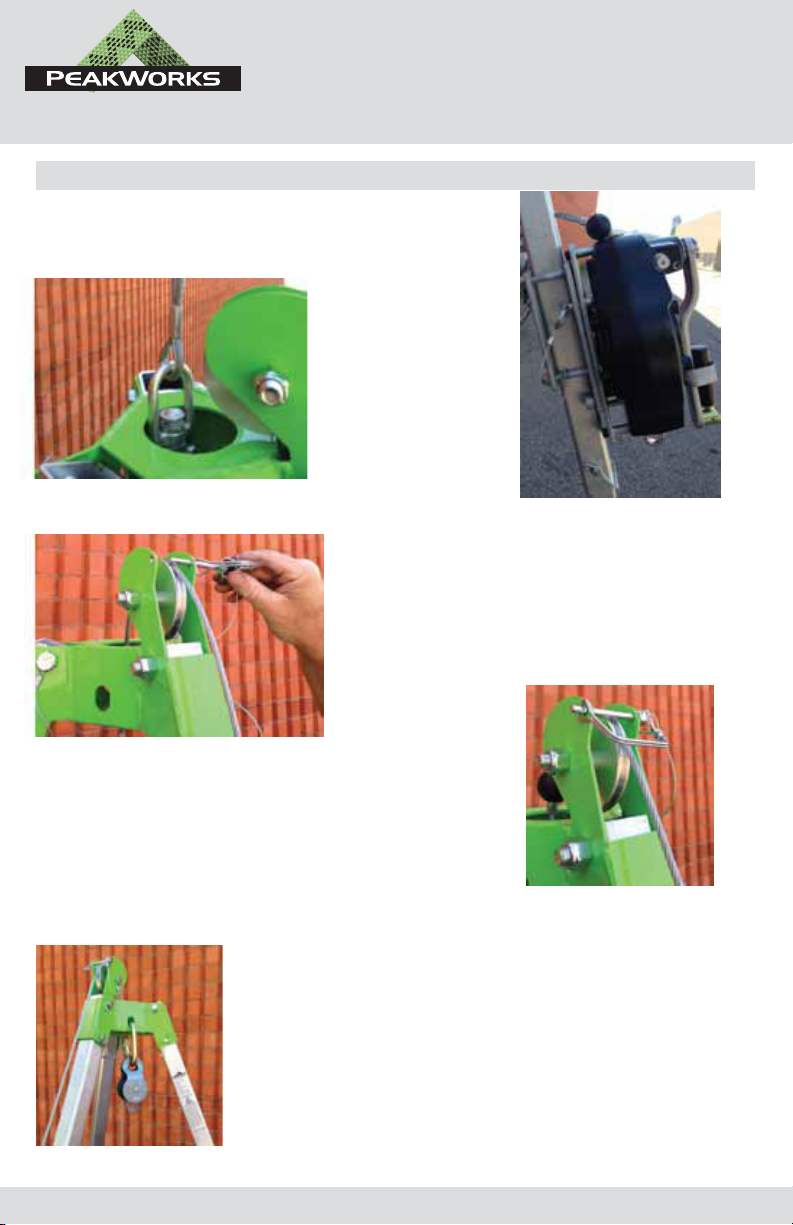
•Check to ensure all detent pins t tightly and are installed correctly
•Check to ensure detent pin on SRL bracket is installed correctly
•Check for misaligned, cracked or bent components
•Check to ensure the pulley runs freely and not bent or misaligned
•Check to ensure that the chain is not kinked or damages
•Check to ensure that any holes are not damaged
•Check to ensure that the inner leg moves freely inside the outer leg when not pinned
•Check to ensure the mounting bracket for the SRL-33303-50 is installed correctly
•Check to ensure that there are not signs that the product as been subjected to a fall arrest
If any deciencies are found that may aect the integrity or operation of the tripod please contact
PeakWorks at 1-877-887-3259 or email [email protected]
The PeakWorks Tripod is designed for ONE person ONLY and is capable of supporting a 5,000 lbs. (22 kN)
static load or provides a 2:1 safety factor when using an approved PeakWorks self retracting lifeline or
3-way. The tripod should be set up on a stable surface capable of withstanding 5,000 lbs. (22 kN)
The top pulley is designed as a suitable anchorage connector. If necessary there is 3 slots on the side of the
tripod head that can be used as secondary anchorage connectors or for a connector for the top attendant.
Before Use

INC
TM
WWW.PEAKWORKS.CA
7
Labels

INSPECTION LOG
INC
TM
WWW.PEAKWORKS.CA
8
INSPECTION
DATE RESULTS
CORRECTIVE
ACTION
MAINTENANCE
PERFORMED
INSPECTION
CONDUCTED BY
1
2
3
4
5
6
7
8
9
10
Table of contents