Peavey 3D Mix Pro User manual

3D Mix Pro
Professional DJ Mixing Console
Operating Guide
™

Intended to alert the user to the presence of uninsulated Òdangerous voltageÓ within the productÕs
enclosure that may be of sufficient magnitude to constitute a risk of electric shock to persons.
Intended to alert the user of the presence of important operating and maintenance (servicing)
instructions in the literature accompanying the product.
CAUTION: Risk of electrical shock Ñ DO NOT OPEN!
CAUTION: To reduce the risk of electric shock, do not remove cover. No user serviceable parts inside. Refer
servicing to qualified service personnel.
WARNING: To prevent electrical shock or fire hazard, do not expose this appliance to rain or moisture. Before
using this appliance, read the operating guide for further warnings.
Este s’mbolo tiene el prop—sito, de alertar al usuario de la presencia de Ò(voltaje) peligrosoÓ que no tiene
aislamiento dentro de la caja del producto que puede tener una magnitud suficiente como para constituir
riesgo de corrientazo.
Este s’mbolo tiene el prop—sito de alertar al usario de la presencia de instruccones importantes sobre la
operaci—n y mantenimiento en la literatura que viene con el producto.
PRECAUCION: Riesgo de corrientazo Ñ ÁNo abra!
PRECAUCION: Para disminu’r el riesgo de corrientazo, no abra la cubierta. No hay piezas adentro que el usario
pueda reparar. Deje todo mantenimiento a los tŽcnicos calificados.
ADVERTENCIA: Para evitar corrientazos o peligro de incendio, no deje expuesto a la lluvia o humedad este
aparato Antes de usar este aparato, Iea m‡s advertencias en la gu’a de operaci—n.
Ce symbole est utilisŽ pour indiquer ˆ lÕutilisateur la prŽsence ˆ lÕintŽrieur de ce produit de tension non-
isolŽe dangereuse pouvant •tre dÕintensitŽ suffisante pour constituer un risque de choc Žlectrique.
Ce symbole est utilisŽ pour indiquer ˆ lÕutilisateur quÕil ou quÕelle trouvera dÕimportantes instructions sur
lÕutilisation et lÕentretien (service) de lÕappareil dans la littŽrature accompagnant le produit.
ATTENTION: Risques de choc Žlectrique Ñ NE PAS OUVRIR!
ATTENTION: Afin de rŽduire le risque de choc Žlectrique, ne pas enlever le couvercle. Il ne se trouve ˆ lÕintŽrieur
aucune pi•ce pouvant •tre reparŽe par lÕutilisateur. Confier IÕentretien ˆ un personnel qualifiŽ.
AVERTISSEMENT: Afin de prŽvenir les risques de dŽcharge Žlectrique ou de feu, nÕexposez pas cet appareil ˆ la
pluie ou ˆ lÕhumiditŽ. Avant dÕutiliser cet appareil, lisez les avertissements supplŽmentaires situŽs dans le guide.
Dieses Symbol soll den Anwender vor unisolierten gefŠhrlichen Spannungen innerhalb des GehŠuses
warnen, die von Ausreichender StŠrke sind, um einen elektrischen Schlag verursachen zu kšnnen.
Dieses Symbol soll den Benutzer auf wichtige Instruktionen in der Bedienungsanleitung aufmerksam
machen, die Handhabung und Wartung des Produkts betreffen.
VORSICHT: Risiko Ñ Elektrischer Schlag! Nicht šffnen!
VORSICHT: Um das Risiko eines elektrischen Schlages zu vermeiden, nicht die Abdeckung enfernen. Es befinden
sich keine Teile darin, die vom Anwender repariert werden kšnnten. Reparaturen nur von qualifiziertem
Fachpersonal durchfŸhren lassen.
ACHTUNG: Um einen elektrischen Schlag oder Feuergefahr zu vermeiden, sollte dieses GerŠt nicht dem Regen
oder Feuchtigkeit ausgesetzt werden. Vor Inbetriebnahme unbedingt die Bedienungsanleitung lesen.
2

3D MIX PROª
The 3D Mix Proªis a two channel, two-mic DJ mixer, with SRS¨stereo enhancement circuitry to
enlarge the space of the left-right stereo field. Each stereo channel has three-band equalization with
22 dB of cut and 12 dB of boost to allow for creative mixing of different frequency bands. A signal
present LED and a cue switch are provided to check the signal.
The microphone inputs have individual level controls and signal present LEDs. They share a two
band EQ, a 75 Hz low cut filter (non-defeatable), and a mute switch. Phantom power (15 V) is
available to power condenser mics.
If external effects are desired, a music only loop function Ñ enabled by a switch and monitored with
its own cue switch Ñ allows the insertion of external components such as delay, flange, or other
special effects into the music signal path. Built into this path is the SRS system to give a greater
depth to the stereo image. A special ÒcollapseÓ switch toggles the signal from the width set by the
SRS space control to mono, for dramatic spatial effects on the fly.
A cueing feature has been provided to check the status of Channels 1 and 2 and the loop return
before they are routed to the main outputs. This signal drives the headphone and booth outputs. A
headphone pan control and a split switch give the DJ other ways to compare cue and main signals.
In addition to the main servo-balanced (TRS) output, the 3D Mix Pro has unbalanced (phono) and
tape (-10 dB) outputs. A third order, 40 Hz rumble filter can be switched in to keep inaudible, power-
robbing, low frequency energy from the speakers. A dual twelve segment LED display indicates the
main output level. The 3D Mix Pro is powered by an internal power supply.
FEATURES
Two Distinct Stereo Input Channels:
Features per channel
Two selectable stereo inputs
One input selectable to phono or line (rear)
CD/Phono(Line) switch
100 mm smooth operating fader
Three-band active EQ with extreme 22 dB cut
Input gain trim control
Gold-plated RCA connectors
Cue switch w/LED
Signal present LED
Two Microphone Inputs:
Features per input
XLR balanced input jack
Rotary level control
Signal present LED
15 V phantom power
3
ENGLISH

Master mic features
Two-band EQ
Low cut filter (18 dB/oct @ 75 Hz)
Mute switch w/LED
Master Section:
Replaceable ultra smooth X-Fader (45 mm)
Main level
Main balance pan
Booth level
Mono level
Music (no mic) L/R 1/4" loop jacks (post X-Fader)
Loop in/out engage w/LED
Loop cue w/LED
Cue master level
Headphone level
HP selector switch (normal/split)
HP pan (cue/main)
SRS enable switch w/LED
SRS width control (space)
SRS collapse switch (momentary)
Manual voice-over switch w/LED
Main rumble filter (40 Hz) switch (rear)
Stereo 12 seg meters (-33 dB to clip range)
Headphone jack
Booth outputs (1/4")
Tape outputs (RCA)
Main L/R outputs (TRS balanced 1/4" and RCA)
Mono out (1/4" unbalanced)
Two turntable ground posts (rear)
Power switch Ñ rear
Power on LED
IEC AC line input
4

POWER AND GROUNDING
1. Removable AC Power Cord/IEC Socket
This receptacle is for the IEC line cord (included), which provides AC power to the unit. Connect the line
cord to this connector and to a properly grounded AC supply. Damage to the equipment may occur if an
improper line voltage is used. (See voltage marking on unit.) Never remove or cut the ground pin of the line
cord plug. This unit is supplied with a properly rated line cord. When lost or damaged, replace this cord with
one of the proper ratings.
2. Power Switch
This switch applies power to the unit. Press the switch to the (I) position to turn the unit on. Return the switch
to the (O) position to turn it off. The Power LED (24) will illuminate when proper power is supplied to the 3D
Mix Pro.
3. Phono Ground
Grounds from external turntables should be connected at this point. Note: There are two points on the rear of
the unit for convenience.
MAIN OUTPUTS
4. Mono Out
This 1/4" output supplies an unbalanced mono (L+R) signal to an outboard EQ, power amp, lighting system,
or subwoofer crossover etc. The Mono Out level is set by the Mono Level control (29).
BACK PANEL
5
1
23
8
6
5
10 97
4

5. 40 Hz Rumble Switch
The Rumble Switch inserts a low cut filter at the main outputs, rolling the signal off at 40 Hz. Use this switch
to eliminate turntable rumble and excessive low frequency energy. Using the rumble switch in this manner will
increase amplifier headroom.
6. Main TRS Balanced Outputs (L and R)
These 1/4" balanced stereo outputs are the preferred method of signal transfer from the 3D Mix ProÕs main
outputs to outboard equipment. The 1/4" connectors are Tip-Ring-Sleeve (TRS), where the tip is positive, the
ring is negative, and the sleeve is ground. Use these Left and Right connectors for optimum power amp noise
rejection. These outputs are also compatible with unbalanced (TS) inputs. The signals at this output are
controlled by the Main Level control (26).
7. Main RCA Unbalanced Outputs (L and R)
These RCA (phono) stereo outputs are unbalanced and should be used when the TRS Balanced Outputs are
not practical. You will achieve the same output signal here as with the TRS Balanced Outputs. The
connectors are gold-plated for maximum life and minimal contact resistance.
MONITOR OUTPUTS
8. Tape Outputs (L and R)
The Tape Outputs are duplicates of the RCA Unbalanced Outputs except -10 dB lower in level. They
offer a Left and Right output designed to feed a recording tape deck. These outputs also feature gold-
plated connectors and may be used as an additional output to external line level gear.
9. Booth Outputs (L and R)
These 1/4" unbalanced stereo outputs are used to feed the booth (or monitor) amplifiers. They have the same
signal as the headphones, but have their own level control. With the Headphone Select switch in the ÒNormalÓ
position, the signal determined by the Headphone Pan control (31) will be present. In the ÒSplitÓ mode, the left
signal will be a sum of the L+R cue signals and the right signal will be a sum of the L+R main signals. This
allows you to monitor the cue on the left and the main on the right. The Booth Output level is always
controlled by the master Booth Level control (28).
EFFECTS SEND/RETURN
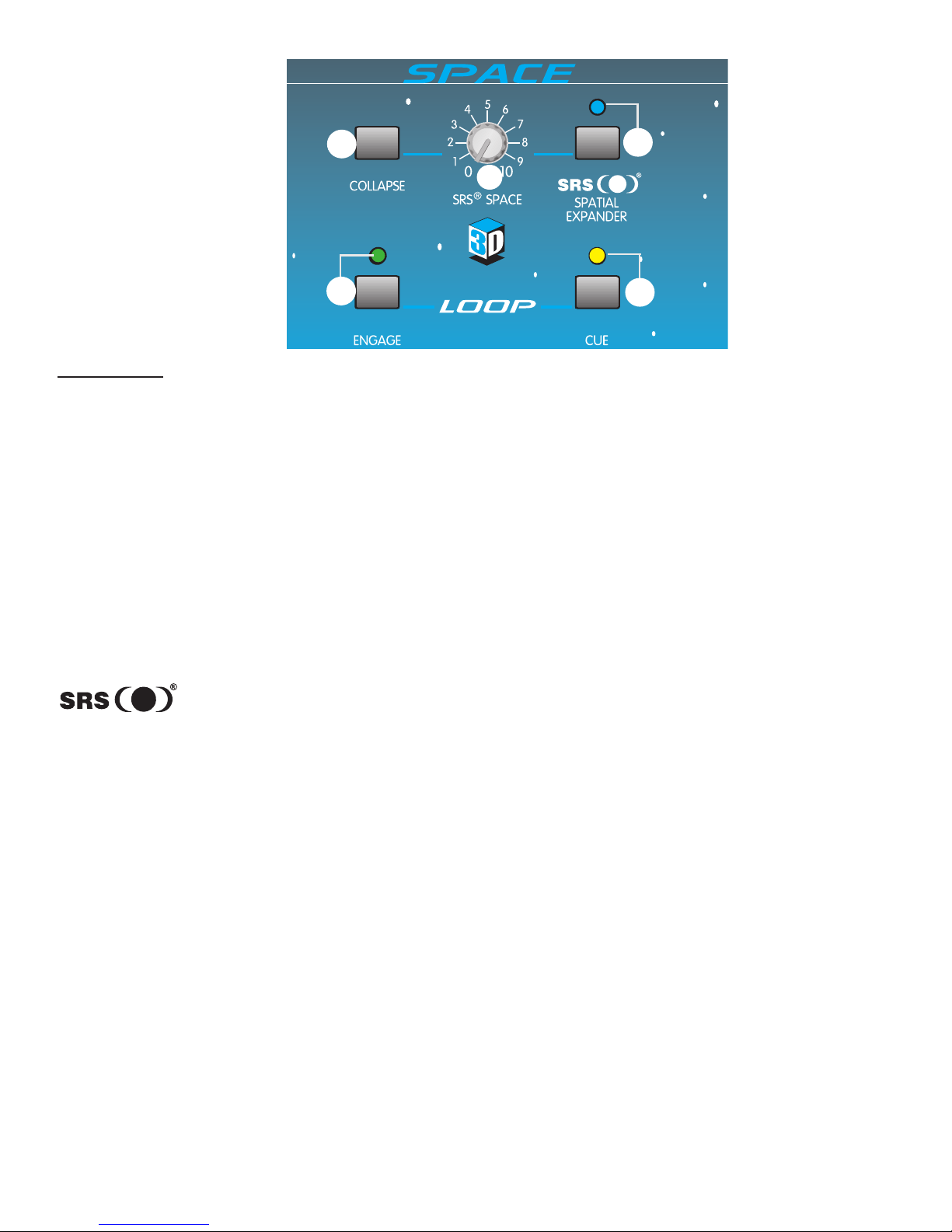
10. Effects Loop (L and R)
Stereo 1/4" TRS jacks are provided for use with external effects units such as delays, reverbs, exciters, etc.
Both jacks (L and R) are wired so that the tip is the send and the ring is the return. Of course, the sleeve is a
common ground. The Effects Loop is post X-Fader, meaning that the X-fader controls what is being sent to
your effects. Signal is present at the Effects Loop sends at all times, so it can be cued but not applied to the
mains until the Loop Engage button (37) is pressed. (The indicator light will illuminate.) Effects can be
checked during a cue by pressing the Loop Cue switch (38).
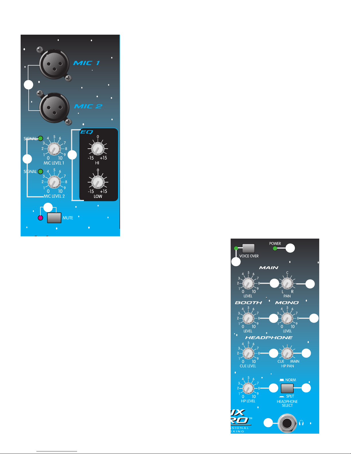
INPUT CHANNELS 1 AND 2
The following section will cover information pertaining to the input channels. Since the
3D Mix Pro has two, identical, feature-packed channels, all descriptions in this section
pertain to both channels. For ease of explanation, this section is divided into two sub-
sections: INPUTS and CONTROLS/INDICATORS.
INPUTS
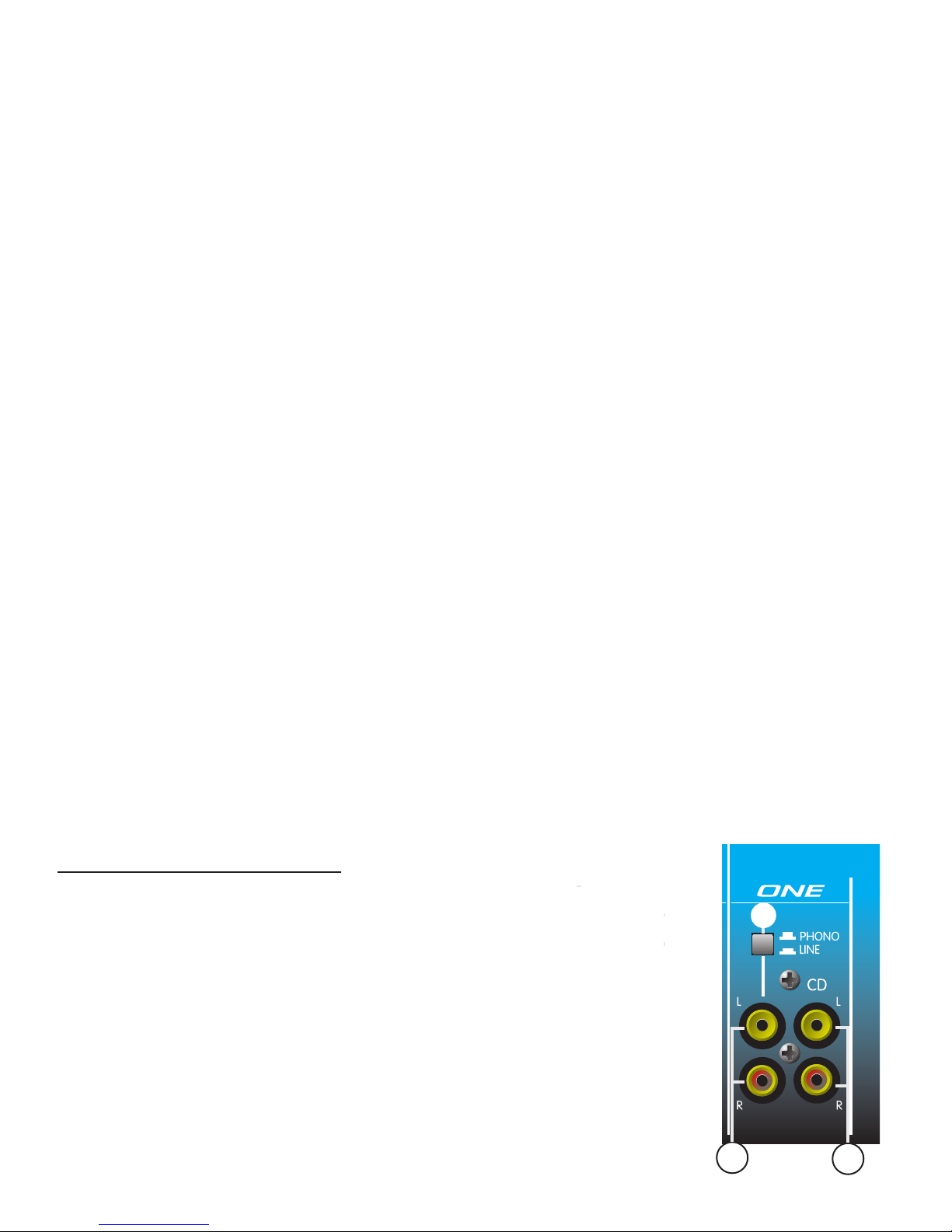
11. CD/Line Level Input
These gold-plated, stereo RCA jacks are provided for connection to external devices
such as a CD, Minidisc, or DAT player. DO NOT USE THIS CONNECTION AS AN
INPUT FOR TURNTABLES.
12. Phono/Line Level Input
This stereo input can be used for two types of equipment as determined by the
Phono/Line switch (13). With the switch in Phono position, this input will accept the
6
11
13
12

output from a turntable cartridge. By placing the switch in the Line position, you can adjust this input to
handle line level signals from a CD, Minidisc, or DAT player. An improper setting can result in severe clipping
and distortion.
13. Phono/Line
This switch changes the input gain and equalization of the Phono/Line Level Input (12) to accommodate
either a Phono or Line level signal. With the switch in, the input is set for line level signals. In the up position,
the switch sets the input for low level cartridge signals. This switch does not affect the CD/Line Level Input (11).
CAUTION: DO NOT CHANGE THE PHONO/LINE SWITCH FROM THE LINE POSITION TO THE
PHONO POSITION WHILE MATERIAL IS BEING PLAYED. A MAJOR CHANGE IN GAIN IS
INTRODUCED, WHICH WILL RAISE YOUR SIGNAL LEVEL DRASTICALLY. THIS COULD RESULT IN
DAMAGE TO BOTH HEARING AND EQUIPMENT.
CONTROLS/INDICATORS
14. Input Selector
The Input Selector switch determines which stereo pair of RCA inputs will
be present on the channel. In the CD position, the CD/Line Level Input (11)
is utilized by the channel. When placed in the Phono/Line position, the
channel uses the Phono/Line Level Input (12). This switch effectively gives
you four inputs for connecting a variety of material sources.
15. Signal Present LED
This LED illuminates to indicate that a signal is present on the channel
(prefader). Signals below the -20 dBu level will not illuminate the LED and
need to be adjusted higher with the Gain (16) adjustment control.
16. Gain
The Gain control adjusts the input gain of the selected inputs. Use the
Gain control to reduce strong signals and to amplify weaker signals. With
the Channel Fader (19) set to 0 dB, adjust the gain control to a nominal
output. The MIN position will produce no output and the MAX position will
produce 6 dB of gain.
17. EQ
The EQ section consists of three active equalization controls: Hi, Mid, and
Low. A shelving type filter is used for the Hi and Low, centered at 10 kHz
and 70 Hz respectively. The Mid EQ is of the peaking type and is centered
at 850 Hz. Each control offers a boost of up to +12 dB or a cut of up to
-22 dB for creative mixing techniques.
18. Cue/Cue LED
This switch allows the channelÕs signal to be present in the Headphone and the Booth Outputs. In typical
operation, only the Cue switch from one channel should be activated at any given time. While one channel is
playing, the other is usually in cue. Thus, you should find yourself pressing these buttons simultaneously and
quite often throughout a show. The Cue LED will illuminate when the cue is active for the channel.
19. Channel Fader
This 100 mm stereo fader offers a smooth transition from infinite cut to +10 dB of boost. Use this control after
your input gain and EQ have been set. Use the Stereo Level Meters to monitor the level from the Channel
Fader. The signal level determined by the Channel Fader should stay consistent when crossfading from
channel to channel. In standard practice, this control is generally set to 0 dB for nominal output.
7
14
16
15
17
18
19

MIC INPUTS AND CONTROLS
20. Mic 1/Mic 2 Inputs
Mic 1 and Mic 2 Inputs are balanced XLR types. Each has a separate
Level control but shares a common EQ. A phantom power of +15 VDC
is supplied automatically for those mics that may require it. Care should
be taken when using some wireless mics that cannot work with
phantom power. Consult your wireless mic ownerÕs manual for proper
operation. If phantom power cannot be used it is possible to modify
your unit to defeat the phantom power. You may contact an authorized
Peavey Service Center for more information.
21. Mic Signal Level/Indicator
The Mic 1 and Mic 2 Level controls adjust the input level of their
respective mics. Turning the control fully clockwise (+45 dB) will result
in maximum gain. Both level controls have a signal present LED
Indicator which illuminates when the signal level exceeds -40 dBu.
22. Mute Switch/Indicator
The Mute Switch defeats both mics so that they become inactive when
mic silence is desired. Mute is indicated when the Mute LED Indicator
illuminates.
23. Mic EQ
This two-band (Hi and Low) active equalization affects only the Mic 1
and Mic 2 signals. The Hi EQ is centered at 10 kHz and the Low at
80 Hz. Both are of the shelving type and offer between 15 dB of gain
and 15 dB of cut. Built into the EQ path is a 75 Hz 18 dB/oct low cut
filter to reduce breath pops and handling noise. This has no user
controls and canÕt be defeated.
MASTER SECTION
24. Power LED
This LED illuminates when power is supplied to the unit and the unit is
turned on.
25. Voice-over
This button lowers the level of the music 10 dB to accommodate speech
from the two mics. The cue and mic signals are not affected. Use this
feature to introduce material when using Mic 1 or Mic 2. It is also useful
for Òpunching inÓ to material for announcements. The Voice Over button is
latching. You must push it again to return to normal levels. The Voice Over
LED will illuminate when Voice Over is activated.
26. Main Level
The Main Level control is the master volume for Outputs (6), (7), and (8).
These are the main (floor) outputs of the mixer. Adjusting this control fully
clockwise will result in maximum signal level at these outputs.
27. Main Pan (L-R)
Use this control in conjunction with the Stereo Output Level Indicator (35)
to balance the Left and Right signal levels. As one side is boosted, the
other is cut.
8
20
22
21 23
34
32 33
30 31
28
26 27
24
25
29

28. Booth Level
Use this control to adjust the stereo Booth Output (9) level. Adjusting this control fully clockwise will result in
maximum signal level. This output is usually used for local monitoring when headphones are not convienient.
29. Mono Level
Use this control to adjust the Mono Out (4) level. Adjusting this control fully clockwise will result in maximum
signal level. This output is a sum of the left and right main signals (prefader), and can be used to drive a
lighting system or subwoofer crossover EQ and amp.
30. Headphone Cue Level
Use this control to set the level of the cue material present in the Headphone and Booth Outputs. With the
Headphone Select switch (33) set to Normal, adjust this control to a comfortable level and the Headphone
Pan (31) fully counterclockwise to listen to the cue signal in the headphones. The Headphone Cue Level
control should be set in conjunction with the Headphone Pan control to achieve the desired headphone mix.
31. Headphone Pan
Use this control to pan the material in the headphoneÕs between cue and mains while the Headphone Select
switch (33) is in the Normal position. Increasing one signal level will reduce the other. While the switch is in
the Split position, the Headphone Pan control will not function.
32. Headphone Level
The Headphone Level control is the master volume control for the Headphone Output (34). Adjusting this
control fully clockwise will result in maximum signal level at the output.
33. Headphone Select
This switch is used to change the headphoneÕs operational mode. When placed in the ÒNormalÓ position,
stereo monitoring of the cue and/or main material is determined by the Headphone Pan (31). As you pan
between the cue and main signals, you will hear both signals in the left and right headphone cups. When the
Headphone Select switch is in the ÒSplitÓ position, the left cup contains the cue material and the right cup
contains the main material. To adjust the level in this mode, use the Cue Level control (30) to set the
preferred balance and the Headphone Level control (32) to set the overall level.
34. Headphone Output
This 1/4" stereo output jack is used to power a set of stereo headphones. The tip is wired left, the ring is
wired right, and the sleeve is wired to ground.
35. Stereo Output Level Indicator
This calibrated pair (L and R) of 12 segment LED meters
illuminates to visually indicate program output levels. At the
top of each meter is a clip LED to notify you of extreme
levels and possible distortion caused by overdriving the
signal.
36. X-Fader
This 45 mm stereo slider delivers crossfade
capability between Channels 1 and 2. Adjusting
this slider from its maximum left position to its
maximum right position will pan the main output
from being completely Channel 1 to completely
Channel 2. The interim from left to right produces a combination of both, allowing a smooth transition from
one channel to the other. NOTE: The X-Fader is replaceable by removing the two outside mounting
screws on the top of the unit. Once the screws have been removed, the slider can be pulled out and
replaced with ease.
9
35
36
Remove these screw to
replace the X-Fader.

EFFECTS
The following section describes the two effects capabilities of the 3D Mix Pro. It is divided into two sub-
sections for clarity and ease of explanation. Those sections are labeled EFFECTS LOOP CONTROLS and
SRS SPATIAL EXPANDER.
EFFECTS LOOP CONTROLS
37. Engage
Pushing this switch in (down) activates the Effects Loop (10) so that the main signal runs through any
external effects units connected to it. It is possible to listen to the effects in the cue by pressing the Loop
Cue button (38). The Engage LED will illuminate to indicate the Effects Loop is active.
38. Loop Cue
Pushing this button in (down) places the effects signal from the loop on the cue bus. This allows you to listen
to what your effects are doing within the headphones or booth. The Cue LED will illuminate to indicate that
the Loop Cue is active.
SPATIAL EXPANDER
The 3D Mix Pro gets its name from the three-dimensional qualities of its built-in SRS effect. The SRS Spatial
Expander creates a three-dimensional sound image from any audio source with only two conventional stereo
speakers. This effect renders greater stereo separation and disperses sound more evenly throughout a room.
Therefore, it produces a better stereo image around a larger area, making speaker placement and listener
location less critical. You will find that it broadens your listening area and actually restores live performance
ambience to your program material.
39. SRS Enable
This button activates the SRS effect when pushed in (down). The SRS enable LED will illuminate to indicate
the SRS Spatial Expander is active.
40. SRS Space
The SRS Space control is used to broaden the stereo separation between the Left and Right outputs.
Adjusting this control fully clockwise will result in maximum stereo imaging/separation.
41. SRS Collapse
Pressing this button will momentarily defeat the Space function of the SRS effect. It is called ÒCollapseÓ due
to its effect on the stereo separation. It collapses the stereo fields from a widened spatial condition to a mono
condition. The SRS Collapse switch is another great effect that can be used to create a beat or feeling in real
time. By pressing and releasing this button with the beat, a swell/collapse condition occurs that is certain to
become a highlight of your show.
10
41
40
37 38
39

11
THD:
<0.05% (20 Hz - 80 KHz BW)
FREQUENCY RESPONSE:
+0 dB /-1 dB, 20 Hz - 20 kHz
HUM AND NOISE: (22 Hz - 22 kHz BW)
<-110 EIN (mic)
<-90 dBu, all controls off, any output
<-80 dBu nominal settings, gains minimum,
any output
CROSSTALK:
-60 dBu (1 kHz) left to right;
-70 dBu (1 kHz) channel to channel
STEREO CHANNEL EQ (+12 dB, -22dB):
HI: 10 kHz shelving
MID: 850 Hz peaking
LOW: 70 Hz shelving
MIC CHANNEL EQ (+15 dB, -15 dB):
HI: 10 kHz shelving
LOW: 80 Hz shelving
LOW CUT FILTER: 18 dB/oct @ 75 Hz
RUMBLE FILTER:
18 dB/oct @ 40 Hz
MIN INPUT LEVELS FOR 0 dBu OUTPUT:
(All controls at maximum gain settings)
MIC: -57 dBu (1.0 mv RMS); 2 k ohms
LINE/CD: -23 dBu (55 mv RMS); 10 k ohms
PHONO (@ 1KHz): -50 dBu (2 mv RMS); 47 k ohms
SRS CONTROLS:
Space, collapse switch, enable (with LED)
LOOP LEVEL:
0 dBu nominal
SIGNAL INDICATORS (LED):
Signal Present: Indicates the signal has
exceeded the -20 dBu level. 12 Segment
ladder indicates main output level (0 dB =
0 dBu)
PHANTOM POWER:
+15V, both mic inputs
POWER REQUIREMENTS:
15 W 115 VAC or 230 VAC (Export model)
3D MIX PRO SPECIFICATIONS
is a registered trademark of SRS Labs, Inc.Ó

3D MIX PROªBLOCK DIGRAM
12

13
Phono
position
Turntable
CD Player
DeltaFexª
CS¨800s
SP¨115m SP¨115m
Right Booth Left Booth
Input LL
RR
R Out L Out
R In L In
SP¨2G SP¨2G
CS¨800s
CS¨800s
Patch Inputs: CH. A to CH. B
R Out L Out
R In L In
L Main
R Main
SP¨218
SP¨218
Turntable
CD Player
Tape Recorder
Phono
position
Ground
Output
Ground
Input
3D Mix ProªHookup Diagram
Lights
Lighting Controller
In
Out
Subs
XDª 3/4
Low Pass

14
IMPORTANT SAFETY INSTRUCTIONS
WARNING: When using electric products, basic cautions should always be followed, including the following:
1. Read these instructions.
2. Keep these instructions.
3. Heed all warnings.
4. Follow all instructions.
5. Do not use this apparatus near water. For example, near or in a bathtub, swimming pool, sink, wet basement, etc.
6. Clean only with a damp cloth.
7. Do not block any of the ventilation openings. Install in accordance with manufacturerÕs instructions. It should not be placed flat against a wall
or placed in a built-in enclosure that will impede the flow of cooling air.
8. Do not install near any heat sources such as radiators, heat registers, stoves or other apparatus (including amplifiers) that produce heat.
9. Do not defeat the safety purpose of the polarized or grounding-type plug. A polarized plug has two blades with one wider than the other. A
grounding type plug has two blades and a third grounding plug. The wide blade or third prong is provided for your safety. When the provided
plug does not fit into your inlet, consult an electrician for replacement of the obsolete outlet. Never break off the grounding. Write for our free
booklet ÒShock Hazard and GroundingÓ. Connect only to a power supply of the type marked on the unit adjacent to the power supply cord.
10. Protect the power cord from being walked on or pinched, particularly at plugs, convenience receptacles, and the point they exit from the
apparatus.
11. Only use attachments/accessories provided by the manufacturer.
12. Use only with a cart, stand, tripod, bracket, or table specified by the manufacturer, or sold with the apparatus. When a cart is used, use caution
when moving the cart/apparatus combination to avoid injury from tip-over.
13. Unplug this apparatus during lightning storms or when unused for long periods of time.
14. Refer all servicing to qualified service personnel. Servicing is required when the apparatus has been damaged in any way, such as power-
supply cord or plug is damaged, liquid has been spilled or objects have fallen into the apparatus, the apparatus has been exposed to rain or
moisture, does not operate normally, or has been dropped.
15. If this product is to be mounted in an equipment rack, rear support should be provided.
16. Exposure to extremely high noise levels may cause a permanent hearing loss. Individuals vary considerably in susceptibility to noise-induced
hearing loss, but nearly everyone will lose some hearing if exposed to sufficiently intense noise for a sufficient time. The U.S. GovernmentÕs
Occupational and Health Administration (OSHA) has specified the following permissible noise level exposures:
Duration Per Day In Hours Sound Level dBA, Slow Response
890
692
495
397
2 100
1 1/2 102
1 105
1/2 110
1/4 or less 115
According to OSHA, any exposure in excess of the above permissible limits could result in some hearing loss. Ear plugs or protectors to the ear
canals or over the ears must be worn when operating this amplification system in order to prevent a permanent hearing loss, if exposure is in excess
of the limits as set forth above. To ensure against potentially dangerous exposure to high sound pressure levels, it is recommended that all persons
exposed to equipment capable of producing high sound pressure levels such as this amplification system be protected by hearing protectors while
this unit is in operation.
SAVE THESE INSTRUCTIONS!

La 3D Mix Pro es una mezcladora de dos canales y dos entradas de micr—fono para DJs que
cuenta con circuitos SRS estŽreo enhancement para agrandar el espacio del campo estŽreo entre
el canal derecho e izquierdo. Cada canal estŽreo cuenta con ecualizaci—n de tres bandas con 22 dB
de corte y 12 dB de incremento para permitir mezclas m‡s creativas en diferentes bandas de
frecuencias. Un foco LED y un control de cue nos permiten checar la se–al.
Las entradas de micr—fonos tienen controles individuales de nivel y LEDs que indican la presencia
de se–al. Comparten un ecualizador de dos bandas, un filtro de corte de graves a 75 Hz, un control
de mute. TambiŽn tiene capacidad de generar Phantom power para micr—fonos de condensador.
Si se desea usar procesadores de efectos externos, un circuito (loop) se puede crear (encendido
por un switch y monitoreado por su propio switch de cue) que permite la inserci—n de procesadores
como delays, flangers o cualquier otro efecto en la ruta de la se–al. Dentro de este circuito
encontramos el sistema SRS que agranda la profundidad de la imagen estŽreo. Un control especial
denominado ÔcollapseÕ cambia la se–al al ancho denominado por el control espacial SRS a mono,
permitiŽndole crear efectos de espacio dram‡ticos sobre la marcha.
La 3D Mix Pro cuenta tambiŽn con un cue que te permite checar las condiciones de los canales 1 y
2, y los retornos de los circuitos (loops) antes que aparezcan en las salidas principales. La se–al se
hace presente en los aud’fonos y en las bocinas de cuarto de control. Un control de paneo para los
aud’fonos y un switch de split le dan al DJ otras maneras de comparar la se–al principal del cue.
Adem‡s de las salidas principales (TRS), la 3D Mix Pro cuenta con salidas de phono y tape
(-10 dB) desbalanceadas. TambiŽn cuenta con un filtro que corta la informaci—n abajo de los 40 Hz,
para evitar mandar esta energ’a a las bocinas. Un medidor de 12 pasos de LEDs indica el nivel de
salida principal. La 3D Mix Pro es alimentada por una fuente de poder interna.
CARACTERêSTICAS
Dos canales independientes estŽreo:
Caracter’sticas por canal:
Dos entradas estŽreo seleccionables
Una entrada seleccionable a l’nea o ÔphonoÕ (detr‡s)
Switch CD/Phono (l’nea)
Fader suave de 100 mm
Ecualizador activo de tres bandas con corte extremo de 22 dB
Control de nivel de entrada (trim)
Conectores RCA ba–ados en oro
Switch de cue con LED
LED indicador de presencia de se–al
Dos entradas de micr—fono
Caracter’sticas por entrada
entradas XLR balanceada
Control de nivel rotativo
LED indicador de presencia de se–al
Phantom power (15 V)
ESPA„OL
15

Caracter’sticas de micr—fono maestro
Ecualizador de dos bandas
Filtro de corte de graves (18 dB por octava @ 75 Hz)
Control de muteo con LED
Secci—n Maestra (Master)
X-Fader super suave y reemplazable (45 mm)
Nivel maestro (Main)
Control de Paneo del Main
Nivel de cabina
Nivel Mono
Conectores de loop de 1/4" (post X-fader)
Control de incorporaci—n del loop con LED
Loop cue con LED
Nivel maestro del cue
Nivel de aud’fonos
Switch seleccionador de HP (normal/split)
Paneo de HP (cue/main)
Switch para el SRS con LED
Control de apertura del SRS (espacio)
Control de ÔcollapseÕ del SRS (moment‡neo)
Switch manual de voice-over con LED
Corte de graves (40 Hz) en el panel posterior
Medidores de 12 segmentos estŽreo (-33 dB a clip)
Conector de aud’fonos
Salidas para la cabina (1/4")
Salidas para cinta (RCA)
Salidas principales L/R (main) (TRS balanceadas 1/4" y RCA)
Salida Mono (1/4" desbalanceada)
Control de encendido y apagado
LED de presencia de poder
Entrada de l’nea IEC AC
16

PODER Y TIERRA
1. Cable de poder AC y entrada IEC
Este espacio es para el cable de poder incluido, que le provee poder a la unidad. Conecte el cable de
l’nea a este espacio y a un enchufe de pared (con tierra). El equipo puede verse da–ado si se usa
voltaje no apropiado. (VŽase etiqueta en la unidad). Nunca corte o quite el conector de tierra del cable. En
caso de extraviar el cable, asegœrese de conseguir uno de las mismas caracter’sticas.
2. Switch de Poder
Este switch enciende la unidad. Oprima el switch a la posici—n (I) para encenderla. Regrese el switch a la
posici—n (0) para apagarla. El LED de poder (24) se enciende cuando el poder apropiado ha sido
proporcionado a la 3D Mix Pro.
3. Conector de Tierra
Las conexiones de tierra de tornamesas pueden conectarse a este punto. Nota: Hay dos puntos en la parte
trasera de la 3D Mix Pro para su conveniencia.
SALIDAS PRINCIPALES (MAIN OUTPUTS)
4. Salida de Mono
Esta salida de 1/4" proporciona una se–al desbalanceada mono (L+R) a procesadores externos como:
ecualizadores, amplificadores, sistemas de luces, etc. El nivel de esta salida es controlado por el Mono Level
control (29).
PANEL TRASERO
1
23
8
6
5
10 97
4
17

5. Filtro de Graves de 40 Hz
El ÔRumble SwitchÕ inserta un filtro de graves a la salida principal, disminuyendo la se–al abajo de los 40 Hz.
Use este switch para prevenir la vibraci—n de las tornamesas y energ’a excesiva de bajas frecuencias. Al
usar este switch tambiŽn aumentar‡ la capacidad de su amplificador.
6. Salidas Principales TRS Balanceadas
Estas salidas estŽreo balanceadas de 1/4" son la v’a preferida para enviar se–al de la 3D Mix Pro a equipo
exterior. Los conectores de 1/4" son de tipo TRS (Tip-Ring-Sleeve), donde la punta es el positivo, el anillo es
el negativo y la manga es la tierra. Use estos conectores izquierdo y derecho para el menor ruido. Estos
conectores tambiŽn son compatibles con entradas no balanceadas. La se–al de estas salidas es controlada
por el Main Level Control (26).
7. Salidas Principales RCA no Balanceadas
Estas salidas RCA estŽreo (phono) son no balanceadas y deben ser usadas cuando las salidas TRS no son
pr‡cticas. La salida de estos conectores ser‡ igual a la salida de TRS balanceada. Los conectores han sido
ba–ados en oro para asegurar m‡xima vida y m’nima resistencia al contacto.
SALIDAS DE MONITOR
8. Salidas de Cinta
Las salidas de cinta son duplicados de las salidas RCA no balanceadas, excepto que son -10 dB m‡s bajas
en nivel. Ofrecen salida izquierda y derecha dise–adas para alimentar una grabadora de cinta. Estas salidas
tambiŽn cuentan con conectores ba–ados en oro y pueden ser usadas para enviar se–al a aparatos
perifŽricos que acepten nivel de l’nea.
9. Salidas de cabina
Estas salidas de 1/4Õ no balanceadas son usadas para alimentar los amplificadores de la cabina (o monitor).
Tienen la misma se–al que los aud’fonos, pero cuentan con su propio nivel de control. Con el selector de
aud’fonos en la posici—n ÒNormalÓ, la se–al determinada por el control ÔHeadphone PanÕ (31) estar‡ presente.
En la posici—n ÒSplitÓ, la se–al de la izquierda ser‡ la suma de las partes izquierda y derecha de la se–al del
cue y la se–al derecha ser‡ la suma de la se–al izquierda y derecha de la salida principal (Main). Esto le
permite monitorear el cue en la izquierda y el main en la derecha. El nivel de salida de cabina siempre ser‡
controlado por el Master Booth Level control (28).
ENVêO Y RETORNO DE EFECTOS
10. Loop de efectos
Se han proporcionado salidas TRS 1/4" para uso con unidades de efectos externos como delays, reverbs,
excitadores, etc. Los dos conectores (L y R) han sido cableados para que la punta sea el env’o y el anillo el
retorno. Por supuesto la manga es la tierra en comœn. El loop de efectos es post X-fader, de manera que el
X-fader controla lo que se manda al efecto. La se–al estar‡ presente en los env’os para efectos todo el
tiempo, por lo que puede ser preparada (cued), pero no aplicada a la salida principal hasta que el control
ÒLoop EngageÓ (37) sea oprimido. (El foco indicador se iluminar‡). Los efectos pueden ser checados durante
un cue oprimiendo el ÒLoop CueÓ (38).
ENTRADAS DEL CANAL 1 Y2
La siguiente secci—n cubrir‡ informaci—n pertinente a los canales de entrada. Como el 3D Mix Pro cuenta con
dos canales idŽnticos en caracter’sticas, todas las descripciones en esta secci—n se pueden aplicar a
cualquier canal. Para facilitar las explicaciones, esta secci—n es dividida en dos sub-secciones: Entradas y
Controles/Indicadores.
18

ENTRADAS
11. Entrada de nivel de l’nea/CD
Estos conectores RCA ba–ados en oro han sido proporcionados para conectar aparatos
externos como reproductores de CDs o DATs. NO USE ESTE CONECTOR COMO
ENTRADA PARA TORNAMESAS.
12. Entrada de nivel de l’nea/phono
Esta entrada estŽreo puede ser usada por dos tipos de equipo determin‡ndose con el
switch phono/line (13). Con el switch en la posici—n Phono, la entrada aceptar‡ la salida
de una tornamesa. Al cambiar a la posici—n Line, puede ajustar esta entrada para
se–ales con nivel de l’nea como CDs, DATs o Minidiscs. El no usarlo en la posici—n
adecuada puede resultar en saturaci—n y distorsi—n severa.
13. Phono/L’nea
Este switch cambia la ganancia y la ecualizaci—n del nivel de entrada de Phono/L’nea
(12) para recibir ya sea una se–al de phono o de l’nea. Con el switch oprimido, la
entrada recibe se–al de l’nea. Con el switch arriba, la entrada recibe se–ales de cartucho de bajo nivel. Este
switch no afecta la entrada de CD/L’nea (11).
PRECAUCIîN: NO CAMBIE EL SWITCH PHONO/LêNEA DE LA POSICIîN DE LêNEA A LA DE
PHONO MIENTRAS HAYA MòSICA SONANDO. UN CAMBIO BRUSCO DE GANANCIA SE
INTRODUCIRç, AUMENTANDO EL NIVEL DE SU SE„AL DRçSTICAMENTE. ESTO PUEDE DA„AR
SUS O’DOS Y SU EQUIPO.
CONTROLES/INDICADORES
14. Selector de Entrada
Este switch determina cu‡l par estŽreo de entradas RCA estar‡
presente en el canal. En la posici—n CD, el nivel de entrada CD/L’nea
(11) es usado por el canal. Cuando se pone en la posici—n Phono/L’nea,
el canal usa la entrada Phono/L’nea (12). Este switch le da cuatro
entradas efectivas para conectar una variedad de fuentes de mœsica.
15. LED de Presencia de Se–al
Este LED se ilumina para indicar que hay una se–al presente en el
canal (prefader). Se–ales debajo de -20dBu no iluminar‡n el LED y
deben ser ajustadas con el control de Ganancia (16).
16. Ganancia
El control de Ganancia ajusta la ganancia de entrada de las entradas
seleccionadas. Use el control de Ganancia para reducir se–ales muy
fuertes y para amplificar se–ales dŽbiles. Con el Fader de Canal (19) en
0 dB, ajuste el control de Ganancia a una salida nominal. L a posici—n
MIN no producir‡ ninguna se–al de salida y la posici—n MAX producir‡
6 dB de ganancia.
17. Ecualizador
La secci—n de EQ consiste en tres controles activos de ecualizaci—n: Hi
(altas), Med (medias) y Low (bajas). Un filtro tipo ÒshelvingÓ es usado
para los controles de altas y bajas frecuencias, centrado en 10kHz y
70 Hz respectivamente. El ecualizador de frecuencias medias es el tipo
ÒpeakingÓ y est‡ centrado en 850 Hz. Cada control ofrece un aumento
(boost) de hasta +12 dB o un corte de hasta -22 dB para tŽcnicas
creativas de mezcla.
14
16
15
17
18
19
11
13
12
19

18. LED cue/cue
Este switch permite que la se–al del canal estŽ presente en las salidas de aud’fonos y de cabina. En una
operaci—n t’pica, s—lo el switch de cue de un canal debe estar activado en un momento dado. Mientras un
canal estŽ sonando, el otro est‡ usualmente en cue. Por ende, usted debe presionar estos botones
simult‡neamente y muy a menudo durante una presentaci—n. El LED de Cue se iluminar‡ cuando el cue estŽ
activado para el canal.
19. Fader de Canal
Este fader estŽreo de 100 mm ofrece una transici—n suave de corte infinito a +10 dB de aumento. Use este
control despuŽs de que su ganancia de entrada y ecualizador estŽn listos. Use los Medidores de Nivel
EstŽreo para monitorear el nivel del Fader de Canal. El nivel de la se–al determinado por el Fader de Canal
debe ser consistente al hacer ÒcrossfadingÓ de canal a canal. En pr‡cticas est‡ndar, este control
generalmente se ajusta a 0 dB para una salida nominal.
ENTRADAS DE MICRîFONO Y CONTROLES
20. Entradas Mic 1/Mic 2
Son entradas balanceadas de tipo XLR. Cada una tiene un control
separado de nivel, pero comparten un ecualizador. Un phantom power
de +15 VDC es suministrado autom‡ticamente para aquellos
micr—fonos que lo requieran Debe tener cuidado al usar algunos
micr—fonos inal‡mbricos que no funcionan con phantom power.
Consulte el manual de su micr—fono inal‡mbrico para saber c—mo
operarlo correctamente. Si el phantom power no debe usarse, es
posible modificar su unidad para eliminar el phantom power. Puede
contactar un centro de servicio autorizado de Peavey para mayor
informaci—n.
21. Indicador/Nivel de Se–al de Micr—fono
Los controles de Nivel Mic 1 y Mic 2 ajustan el nivel de entrada de sus
respectivos micr—fonos. El girar el control totalmente hacia la derecha
(+45dB) resultar‡ en una ganancia m‡xima. Ambos controles de nivel
tienen un indicador LED de presencia que se ilumina si la se–al
excede -40dBu.
22. Switch Indicador de Mute (Silencio)
El switch de mute elimina la se–al de ambos micr—fonos si esto se
desea. El mute es indicado cuando el Indicador LED de Mute se
ilumina.
23. Ecualizador de Micr—fono (Mic EQ)
Esta ecualizaci—n activa de dos bandas (altas y bajas) afecta s—lo las
se–ales de los Mic 1 y Mic 2. El ecualizador de altas est‡ centrado en
10kHz y el de bajas en 80Hz. Ambos son del tipo ÒshelvingÓ y ofrecen entre 15 dB de ganancia y 15 dB de
corte. Integrado en la ruta del ecualizador est‡ un filtro de bajas a 75Hz 18 dB/oct para reducir el ruido de
ÒpopsÓ y de manejo. Este filtro no tiene controles para el usuario y no puede ser cancelado.
20
20
22
21 23
Table of contents
Languages:
Other Peavey Music Mixer manuals

Peavey
Peavey PVi 8500 User manual

Peavey
Peavey 260 User manual

Peavey
Peavey XR 1212 User manual

Peavey
Peavey AMA 1200 User manual

Peavey
Peavey PM 1 User manual

Peavey
Peavey S 4 User manual

Peavey
Peavey MPA 700 User manual

Peavey
Peavey Mark IV User manual

Peavey
Peavey S-14P User manual

Peavey
Peavey XR 1000L User manual

Peavey
Peavey XR 1220 User manual

Peavey
Peavey PV 8 User manual

Peavey
Peavey AAM 3243 User manual

Peavey
Peavey SMRTM 821a User manual

Peavey
Peavey PA 1000S User manual

Peavey
Peavey S-14 User manual

Peavey
Peavey SheffieldPro 1200 User manual

Peavey
Peavey R6M 6*4 User manual

Peavey
Peavey FX Mixer Series User manual

Peavey
Peavey PV 8 USB User manual