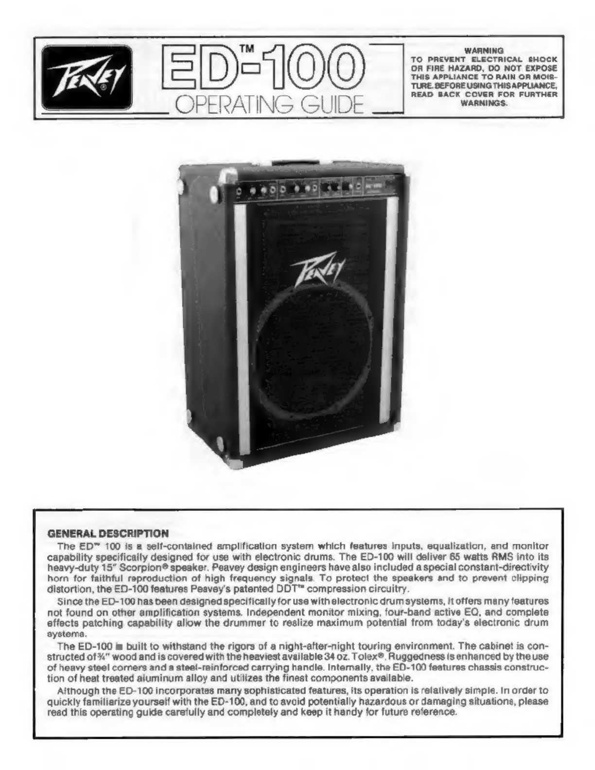
Peavey ED-100 User manual
Other Peavey Speakers manuals

Peavey
Peavey DTH 218 User manual

Peavey
Peavey PR 2652 User manual

Peavey
Peavey ShowFex User manual

Peavey
Peavey Impulse Impulse 1280 User manual

Peavey
Peavey Escort 5000 User manual

Peavey
Peavey Pro Rider User manual

Peavey
Peavey Black Widow 1208-4sps BWX User manual

Peavey
Peavey Impulse Impulse 6 User manual

Peavey
Peavey SP 6 User manual

Peavey
Peavey Scorpion Ultra 12 User manual

Peavey
Peavey HDH M User manual

Peavey
Peavey DTH 4210 User manual

Peavey
Peavey Scorpion S 12825 System manual

Peavey
Peavey HKS 12 User manual

Peavey
Peavey PV 12M User manual

Peavey
Peavey Impulse 115 User manual

Peavey
Peavey SP 4 User manual

Peavey
Peavey PVX p 10 User manual

Peavey
Peavey 115 TLM User manual

Peavey
Peavey QW-4 User manual