Pegasus TFV2000D-E User manual

MITSUBISHI TRANSPORT REFRIGERATION UNIT
TFV2000D-E
PEGASUS
This operation manual is
intended to provide users
with a good knowledge to
use Mitsubishi Refrigeration
Unit safely.
Operate or service the
refrigeration unit only after
you have read this manual
and understand its contents.
Carefully store this manual
in a fixed place so that it is
immediately available for
your reference when you
need it.
OPERATION MANUALOPERATION MANUAL
YEAR:2016
TSJ012A176A
TRANSPORTATION REFRIGERATION DEPARTMENT
3-1, ASAHI, NISHIBIWAJIMA-CHO, KIYOSU, AICHI, 452-8561, JAPAN
Phone : 052-503-9312

- I -
Thank you for your purchase of Mitsubishi Transport
Refrigeration Unit.
Purpose of use and application
This Refrigeration Unit is intended to carry the cargo (with the exception of
volatile, inammable, hazardous matter) keeping inside container temperature
at a certain degree.
If the Refrigeration Unit is used for any purposes other than this purpose, it may
cause accidents or damages.
Important information
●For questions or information, contact your nearest dealer.
●Be sure to follow the contents described in this manual in order to protect
yourself and other people from potential risks of this refrigeration unit and to
prevent it from getting damaged.
●We are not able to foresee all potential risks of this refrigeration unit or
dangers due to mishandling by the customers. Therefore, it is necessary to
take measures for safety in addition to the items described in this manual or
on warning labels.
●For the following works, contact your nearest dealer. If those works were
carried out by customer, the refrigeration unit may lose its performance and
we may not be able to ensure the safety of the customer.
(a) Installation, modication, specication change and disposal for the
refrigeration unit
(b) Maintenance of electric appliances
(c) Abnormal treatments which are not described in this manual
●This product contains uorinated greenhouse gases.
• Refrigerant : R404A (GWP (Global Warming Potential)=3922)
Refer to a label on unit about weight of uorinated greenhouse gases and
CO2 equivalent. ( Refer to pages 4.)
• Form blown with uorinated greenhouse gases : R134a.
(GWP (Global Warming Potential)=1430)

- II -
Operation manual
●This operation manual is prepared for people who speaks English. In case
that person whose native language is not English handles this refrigeration
unit, he or she must be instructed on safety by the customer. Furthermore,
the warning labels described in their native language must be prepared and
stuck on the proper places.
●This operation manual is copyrighted and all rights are reserved by our
company. The drawings and technical information described in this manual
may not, in whole or part, be published, copied, translated for the purposes
other than above-mentioned and reduced to any electronic medium or
machine-readable form without prior written consent with our company.
●This manual also contains the explanation of optional specication.
●The contents of this operation manual may differ from that of the refrigeration
unit used by a customer due to specication change.
●The contents described in this operation manual may be changed without a
prior notice.
●When transferring or lending the refrigeration unit, attach this operation
manual together with the unit so that the operators should be able to have a
good knowledge on safety.
●Keep this operation manual in the vehicle so that it is available for your
reference when you need it..
●Unless otherwise noted, "right" and "left" directions are given as viewed from
the front of the refrigeration unit.
For disposal
Contact your nearest dealer when disposing the refrigeration unit. Observe
the applicable laws and regulations in your country to dispose refrigerants and
cooling water.

- III -
1
5
2
6
3
7
9
4
8
10
Contents
Purpose of use and application -------- I
Important information --------------------- I
Operation manual------------------------- II
For disposal -------------------------------- II
Contents ----------------------------------- III
1 Function of Refrigeration Unit 1
2 Name of each part---------------3
Arrangement plan for main parts ----- 3
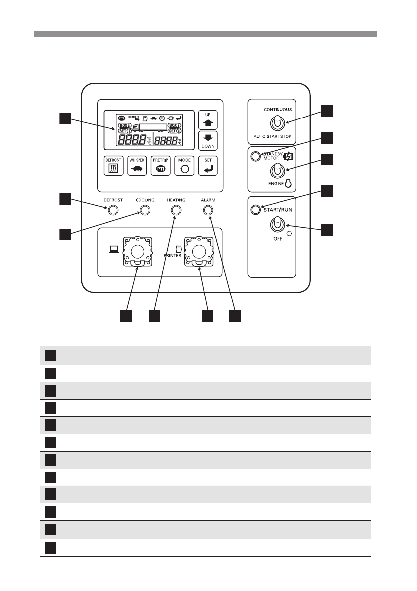
Control panel------------------------------- 5
Switches ------------------------------------ 6
Digital display area ----------------------- 7
Protective devices ------------------------ 8
3 Precaution for safety------------9
Signs on safety---------------------------- 9
Precautions--------------------------------10
General precautions-------------------------- 10
During and after the operation ------------- 11
Inspection/Cleaning/Repair----------------- 12
Loading ------------------------------------------ 12
Handling of electric equipment and power codes
13
Reinstallation of refrigeration unit --------- 14
Modication of the refrigeration unit and
specication change-------------------------- 15
Power supply equipment -------------------- 15
Emergency measure
------------------16
Handling of warning labels ------------18
Prevention of start during inspection work
--21
Clothing and protective equipment--21
Handling of grease and oil-------------21
When abnormal conditions are detected
21
For emergency ---------------------------21
4 Initial setting--------------------- 22
Mode displays and functions----------22
Outline of the user setting mode-----25
Setting the printer (Optional)----------27
Setting the defrost interval timer -----29
Sleep operation setting-----------------30
Resetting the cumulative time 1------31
Setting the clock -------------------------33
5 Operation ------------------------ 35
Power on-----------------------------------36
Switching the drive ---------------------37
Operating with the sub-engine------------- 37
Operating with the motor -------------------- 38
Switching the operation pattern ------39
Selecting the auto start/stop operation -- 39
Selecting the continuous operation------- 39
Operation ----------------------------------41
Stopping the operation -----------------43
Setting temperature ---------------------44
Whisper operation
(Only for of sub-engine drive)---------45
Manual defrost operation --------------46
Starting ------------------------------------------ 46
Stopping ----------------------------------------- 47
Setting the ON timer --------------------48
Setting the OFF timer-------------------50

- IV -
1
5
2
6
3
7
9
4
8
10
Self diagnosis operation
(PTI operation) ---------------------------52
Starting the operation ------------------------ 53
Finishing the operation when no defects
are detected ------------------------------------ 53
When abnormal conditions are
detected ----------------------------------------- 53
6 Loading -------------------------- 54
Preparation before loading ------------54
Loading and unloading -----------------55
Loading procedure --------------------------- 55
Unloading --------------------------------------- 56
7 Inspection------------------------ 57
Precautions for inspection-------------57
Opening of the covers ------------------59
Cover 1 ------------------------------------------ 59
Cover 2 ------------------------------------------ 59
Cover 3 ------------------------------------------ 60
Cover 4 ------------------------------------------ 60
Cover 5 ------------------------------------------ 60
Closing the cover ------------------------61
Daily inspection --------------------------62
Inspection of the cooling water quantity - 62
Inspection of the belts------------------------ 63
Inspection of sub-engine oil quantity ----- 64
Inspection of sub-engine fuel quantity --- 65
Inspection of leakage and wiring condition
----------------------------------------------------- 66
Inspection with the sight glass ------------- 66
When operating the refrigeration unit
with low inside container temperature
continuously for a long period.------------- 66
Periodic inspection ----------------------67
Periodic inspection check sheet -----68
Details of applicable oils and cooling
water ----------------------------------------70
8 Sleep operation ---------------- 71
Sleep operation --------------------------71
Preparation for the sleep operation------- 71
9 For emergency ----------------- 72
Error display-------------------------------72
Switching the "Normal display" and
"Current error display" ------------------73
Switching from "Normal display screen" to
"Current error display mode" --------------- 73
Keeping "Current error display mode"
continuously ------------------------------------ 73
Switching from "Current error display
mode" to "Normal display screen" -------- 73
Countermeasures------------------------74
Changing the fuse ---------------------------- 74
When you contact your nearest dealer -- 75
Resuming operation after an error stop
--75
List of error codes -----------------------76
10 Specication -------------------- 79

- 1 -
1 Function of Refrigeration Unit
1
5
2
6
3
7
9
4
8
10
This refrigeration unit has following functions.
(1) Drive switching function
This is the function to switch the drive (motor/sub-engine) manually.
Refer to pages 37 and 38 for how to switch the drive.
Regarding the function to switch from the motor drive operation to the
engine drive after a power failure, contact your nearest dealer.
(2) Operation pattern switching function
This is the function to switch operation pattern (continuous operation/
automatic start/stop operation).
Refer to pages 39 and 40 for how to switch operation pattern.
(3) Defrosting operation function
This is the function to protect evaporator from frosting during cooling
operation and to prevent refrigerating power from decreasing.
There are following 2 methods to start defrosting operation.
1) Automatic defrosting operation
Defrosting starts automatically by the timer setting.
Refer to page 29 for defrosting timer setting.
2) Manual defrosting operation
Defrosting starts forcibly by pressing the switch of controller.
Refer to pages 46 and 47 for how to operate.
After the defrosting operation completes, the refrigeration unit stops once
and restarts automatically to return to cooling operation.
Defrosting operation will not start when the evaporator temperature is high
even during cooling operation.
(4) Whisper operation function
This is the function to lower the operation sound with xing the sub-engine
at slow speed forcibly during sub-engine driving.
Refer to page 45 for how to operate.

- 2 -
1 Function of Refrigeration Unit
1
5
2
6
3
7
9
4
8
10
(5) Timer operation function
This is the function to set starting time and stopping time of the operation .
Refer to pages from 48 to 51 for how to set.
(6) Self diagnosis operation function (PTI operation)
This is the function to diagnose the refrigeration unit automatically if it has
any trouble or not. Refer to page 52 for how to operate.
(7) Sleep operation function
When the refrigeration unit is not used for 1 week, the unit starts and
runs for 5 minutes automatically so that battery and compressor could be
protected.
Refer to page 30 for how to operate.

- 3 -
2 Name of each part
1
5
2
6
3
7
9
4
8
10
10
11
5
6
7 8
9
1
23 4
Arrangement plan for main parts

- 4 -
2 Name of each part
1
5
2
6
3
7
9
4
8
10
1
Refrigeration Unit
18
Alternator
2
Battery
19
Alternator belt (V belt)
3
Fuel lter (for water separation)
20
Standby motor
4
Fuel tank
21
Compressor belt (10-ribbed belt)
5
Opening and closing lever for the cover
22
Sight glass
6
Lock for front cover
23
Air cleaner
7
Commercial power socket (Bottom surface)
24
Compressor
8
Control panel
25
Oil lter
9
Mufer
26
Sub-engine
10
Supply air outlet for evaporator
27
Fuel lter
11
Drain pan
28
Water pump belt (V belt)
12
Reservoir tank
29
Control box
13
Fan belt (6-ribbed belt)
30
Right condenser
14
Right condenser fan
31
Exhaust pipe
15
Radiator cap
32
Main switch
16
Left condenser fan
33
Label (F-Gas)
17
Left condenser
Upper surface view
16
17
18
19
20
21
22
23
24 25 26 27 28 29
32
31
30 15
14131233

- 5 -
2 Name of each part
1
5
2
6
3
7
9
4
8
10
Control panel
1
2
3
4 5 6 7
8
9
10
12
11
1
Digital display area
Inside container temperature, setting temperature and
operation status will be displayed.
2
Defrost indicator lamp (Orange)
This lamp will light during defrosting operation.
3
Cooling operation lamp (Green)
This lamp will light during cooling operation.
4
External device connector This is the connector to connect to the external devices.
5
Heating operation lamp (Orange)
This lamp will light during heating operation.
6
Printer connector This is the connector with a printer.
7
Alarm indicator lamp (Red)
This lamp will light or blink when something abnormal occurred.
8
Operation switch The refrigeration unit will start or stop with this switch.
9
Run indicator lamp (Green) This lamp will light while the refrigeration unit is running.
10
Drive selector switch
Drive can be switched from motor to sub-engine or vice versa.
11
Motor select indicator lamp
(Orange)
This lamp will light when drive is switched to "STANDBY
MOTOR".
12
CONT./AUTO changeover switch
Operation pattern can be changed with this switch.

- 6 -
2 Name of each part
1
5
2
6
3
7
9
4
8
10
Switches
A
B
C
D
EF
G
A
UP Changes the setting temperature and setting screen.
B
DOWN Changes the setting temperature and setting screen.
C
SET Registers the setting.
D
MODE Selects the normal display screen or the setting change screen.
Starts the controller.
E
PRETRIP (PTI) Starts/stops the self diagnosis operation.
F
WHISPER Selects the normal operation or whisper operation.
G
DEFROST Starts the manual defrost operation.

- 7 -
2 Name of each part
1
5
2
6
3
7
9
4
8
10
Digital display area
1
6
2
5
4
3
Explanation of display
1
Left side of digital
display
Inside container temperature during operation will be displayed.
Name of setting mode (code) will be displayed when setting is
changed.
2
Right side of digital
display
Setting temperature will be displayed during operation.
Setting contents will be displayed when setting is changed.
3
Temperature symbol °C will light in case of centigrade and °F will light in case of
Fahrenheit. (Initial setting is in centigrade.)
4
Setting temperature
icon
This icon will light when the display shows setting temperature.
5
Inside container
temperature icon
This icon will light when the display shows inside container
temperature.
6
Function icons Either one of these icons will light when corresponding function
is selected.
------------
Display for self diagnosis operation (PTI) ( Refer to page 52.)
This will light during self diagnosis operation.
----------- Display for communication status with externals.
This will light while communicating with external devices like
remote monitoring device.
-------------- Display for printer (Option)
This will light while sending data to the printer.
------------- Display for Whisper operation
This will light when Whisper operation is selected.
-------------- Display for timer
This will light when the timer operation is selected.
------------- Display for commercial power supply
This will light when the refrigeration unit is connected to
commercial power supply.
-------------- Display for registration
This will light when registration is required.

- 8 -
2 Name of each part
1
5
2
6
3
7
9
4
8
10
Protective devices
This refrigeration unit is provided with the following protective devices to ensure
the safety of the operators.
(a) Main switch
If sub-engine starts during the work such as inspection, it may cause an
accident. In such a case, set this switch to "OFF" so that the safety is
secured.
(b) Buzzer before start
Buzzer sounds 5 seconds before the sub-engine or the motor starts to
announce the start of operation to the surrounding people.
(c) Cover
The cover prevents operators from contacting with the rotating part during
operation.
(d) Detector for opening of cover 1
Opening of the cover 1 for the work such as inspection is detected to
prevent sub-engine from starting. ( Refer to page 59.)
(e) Cover key
Locks are provided to the cover 1 and 5 in order to prevent unintended sub-
engine start or setting change. ( Refer to pages 59 and 60.)
People who handle this refrigeration unit are requested to understand the
functions of these protective devices completely to use it safely. Do not
deactivate these protective devices or do not operate the refrigeration unit in the
situation that the devices are inactivated. It is most important for safety ensuring
to keep functions of the protective devices in normal status continuously.

- 9 -
3 Precaution for safety
1
5
2
6
3
7
9
4
8
10
In this section, necessary safety precautions are provided to prevent accidents
resulting in injuries or death, property damages and environment pollution.
Read and understand contents of the cautions before starting to use this
Refrigeration Unit.
Signs on safety
Signs and Symbols on safety in this operation manual and the warning labels
call the attention of the people who handle this refrigeration unit.
Signs on safety
Kinds Description
Indicates dangerous situation, which if mis-handled,
will result in death, serious injury, and serious
accident such as damage of the refrigeration unit.
Indicates potentially dangerous situation, which if
mis-handle, will result in minor injury or moderate
property damage.
Symbols
Symbols
Description
Symbols
Description
Never perform. Always observe the
instructions.
Disconnect power supply
plug from socket.
Never touch.
Repairs and disassembly
must be done only by
qualied personnel
Other symbol
Other advice for the refrigeration unit is described with the following symbol.
Kind Description
NOTE Useful information for function or performance of equipment
CA
UTION
W
ARNING

- 10 -
3 Precaution for safety
1
5
2
6
3
7
9
4
8
10
Precautions
General precautions
WARNING
Do not place combustible materials in the
vicinity of mufer and exhaust pipe. Do
not park on the area where combustibles
such as falling leaves accumulate on.
• Otherwise, it may cause a re because mufer and exhaust pipe will
be hot.
Do not start the engine in poorly ventilated
places such as an indoor parking lot.
• Otherwise, it may cause carbon monoxide
poisoning due to exhaust gas.
Do not use the refrigeration unit in
the atmosphere which could cause
explosion at such place like gas station.
• Otherwise, it may cause an explosion or a re.
When it is necessary to charge or retrieve the refrigerant
or refrigerating machine oil, be sure to consult the nearest
service center.
• Customer should refrain from attempting to do these on their own.
Otherwise, it could result in serious accident.
Make sure that no one left inside the
container before closing the door.
• He or she might be frozen to death if the
refrigeration unit is operated with someone
inside.
Be sure to carry out the periodic
inspections.
• Otherwise, it may cause troubles of the
refrigeration unit or accidents.

- 11 -
3 Precaution for safety
1
5
2
6
3
7
9
4
8
10
CAUTION
Do not insert sticks or ngers into cold air outlet or inlet.
• Otherwise, it may cause damage of the equipment or injury due to a fan.
Do not climb up, hang down or put your leg onto the
refrigeration unit.
• Otherwise, it may cause damage of the equipment or injury.
Use the refrigeration unit as the equipment for transport
refrigeration.
• Otherwise, it may deteriorate quality of the cargo if it is used for any
other purpose.
Use specied fuel, sub-engine oil, compressor oil and
cooling water. ( Refer to page 70.)
• Otherwise, it may cause troubles if any other materials are used.
During and after the operation
WARNING
Make sure that the cover of
the refrigeration unit is closed
before starting the operation.
• Otherwise, it may cause accidents.
CAUTION
Do not touch the mufer and exhaust pipe during
operation or immediately after the operation.
• Otherwise, it may cause burns, as the mufer and pipe will get hot.
Do not open the radiator cap during operation or
immediately after the operation.
• High temperature steam may blowout and cause burns.

- 12 -
3 Precaution for safety
1
5
2
6
3
7
9
4
8
10
Inspection/Cleaning/Repair
WARNING
Do not disassemble and repair by
yourself.
• Otherwise, it may cause damages or
an electric shock.
CAUTION
When refrigerant and compressor oil leak out or when you
handle antifreeze coolant or sub-engine oil, be careful not to
have them get in your eyes, not to have them contact with
your skin, not to inhale them or not to drink them by mistake.
• Otherwise, it may cause health disorders such as frostbite, loss of
eyesight and pneumonia.
Do not wash the refrigeration unit with a steam washer or
a high pressure washer.
• Otherwise, it may cause a rupture due to pressure rise in the
refrigeration unit or distortions of the condenser n.
Set the "Main switch" to "OFF" to stop the refrigeration
unit and remove the battery terminal and plug for power
code during the inspection and cleaning.
• Otherwise, it may cause injury or an electric shock due to unexpected
start
.
Loading
WARNING
Do not load the volatile or inammable
cargos in the container.
• Otherwise, it may cause an explosion or a re.

- 13 -
3 Precaution for safety
1
5
2
6
3
7
9
4
8
10
CAUTION
Cool down or heat up the cargos to the designated
temperature in advance with other refrigerating device.
• If the cargos are not kept in the designated temperature, it may
deteriorate quality of the cargos due to inside container temperature
rise.
Waterproof the cargos if they need to be.
• Otherwise, it may deteriorate quality of the cargos due to the
spattering water from defrosting.
Handling of electric equipment and power codes
WARNING
•Do not directly splash water on the electric
equipment or wash them with water.
• Never touch the electric equipment
such as power plug and so on or
operate the switches with wet hands.
• Do not modify the power code or apply force
on it, by bending it by force, pulling it strongly
or twisting it, or do not put cargos on it.
• Otherwise, it may cause troubles of electric circuit, damages of power
codes or an electric shock.
• Use 4-core cabtyre cables (conductor
cross section with 8mm2or more)
for power cable. Do not connect it to
extension code.
( Refer to page 38.)
• Use MENNEKES Part no.6 (400V 32A)
for power supply plug.
• Otherwise, it may cause an electric shock or a re due to
the heat and breaking of wire.

- 14 -
3 Precaution for safety
1
5
2
6
3
7
9
4
8
10
WARNING
• Pull out the power code by holding the plug
part at the end of the code.
• Check the plug of the power code for dust.
If there is no dust, insert it rmly.
• Surely protect the power socket with a
cover when it is not used. When the cover
is damaged, repair it immediately.
• Otherwise, it may cause an electric shock or a re due
to the heat, breaking of wire and leaking of water, etc.
CAUTION
Do not start and stop the operation with pulling out or
inserting the power supply breaker or power code.
• Otherwise, it may cause troubles of electric circuit, damages of power
supply code or an electric shock.
Reinstallation of the refrigeration unit
WARNING
Do not reinstall this refrigeration
unit on other container by
yourself. Contact your nearest
dealer in that case.
• The refrigeration unit may fall down
and cause a serious accident due to
improper installation or insufcient strength if the work is performed
by the customer.

- 15 -
3 Precaution for safety
1
5
2
6
3
7
9
4
8
10
Modication of the refrigeration unit and specication change
WARNING
Do not modify the refrigeration
unit or change the specication.
• It may cause a serious accident if
customer modify the refrigeration unit
or change the specication by himself/
herself.
Do not use any refrigerant or refrigerating machine oil other
than those specified. ( Refer to page 79.)
• Otherwise, it may cause explosion or re.
Power supply equipment
WARNING
Be sure to earth the power supply
equipment to supply the electricity to the
refrigeration unit.
• It may cause an electric shock if the earthing
work is not carried out properly.
Be sure to provide a dedicated circuit
and an earth leakage breaker.
• It may cause an electric shock or a re if
there is capacity shortage of electric circuit .
Table of contents