Pentair Pool Products IntelliComm II User manual

IntelliComm II Interface Adapter Installation and User’s Guide
Installation and User’s Guide
IntelliComm® II
Interface Adapter
(For use with IntelliFlo®and IntelliPro®pumps)
IMPORTANT SAFETY INSTRUCTIONS
READ AND FOLLOW ALL
INSTRUCTIONS
SAVE THESE INSTRUCTIONS
24VDC
9 -

IntelliComm II Interface Adapter Installation and User’s Guide
Important Notice: Attention Installer: This manual contains important
information about the installation, operation and safe use of this product.
This information should be given to the owner and/or operator of this
product. READ AND FOLLOW ALL INSTRUCTIONS IN THIS MANUAL.
Contents
IntelliComm®II Interface Adapter Overview ......................................................1
IntelliComm II Interface Adapter Connections .................................................. 2
Connecting to IntelliComm II Input Program Terminals .................................... 2
Connecting Power to IntelliComm II ................................................................. 2
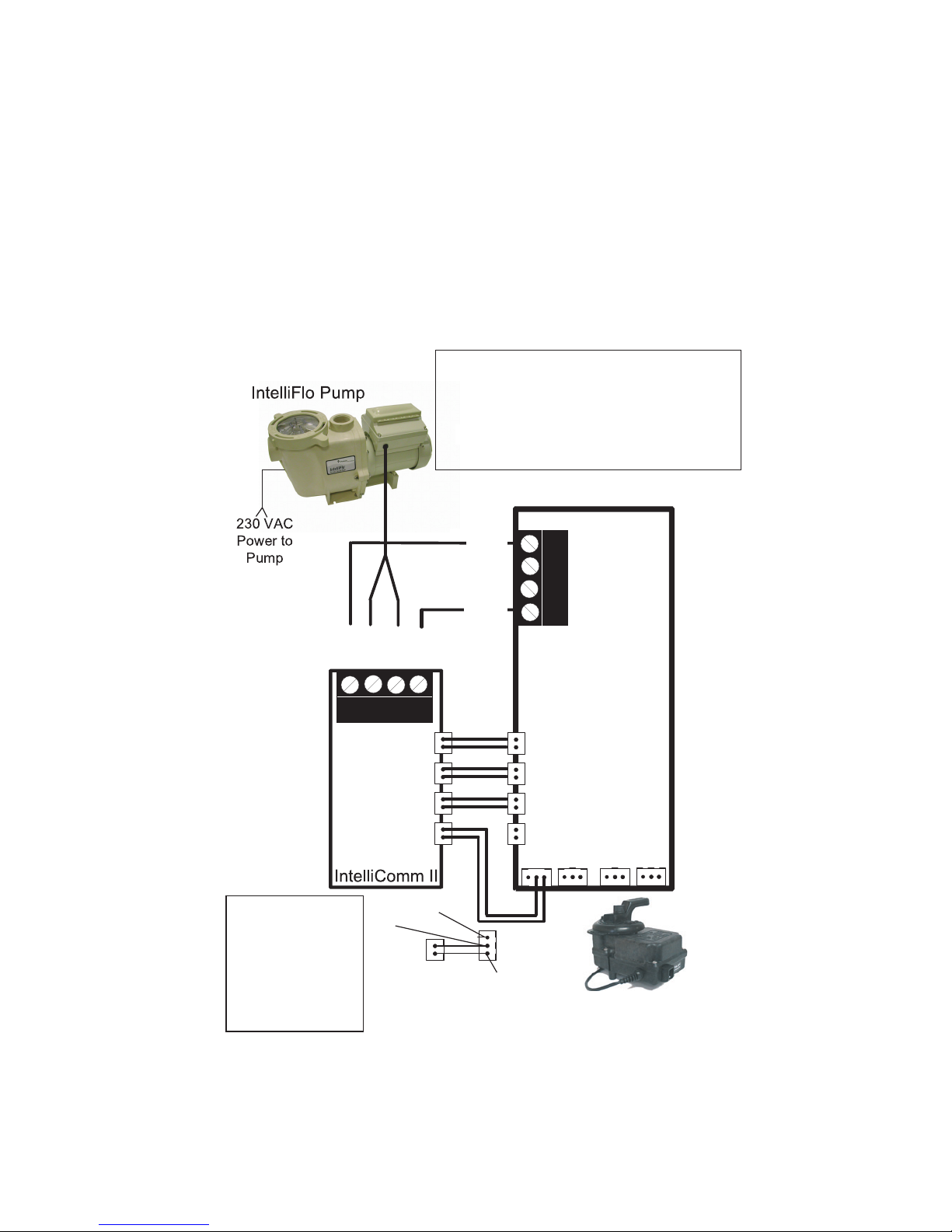
Connecting IntelliComm II to IntelliFlo .............................................................. 3
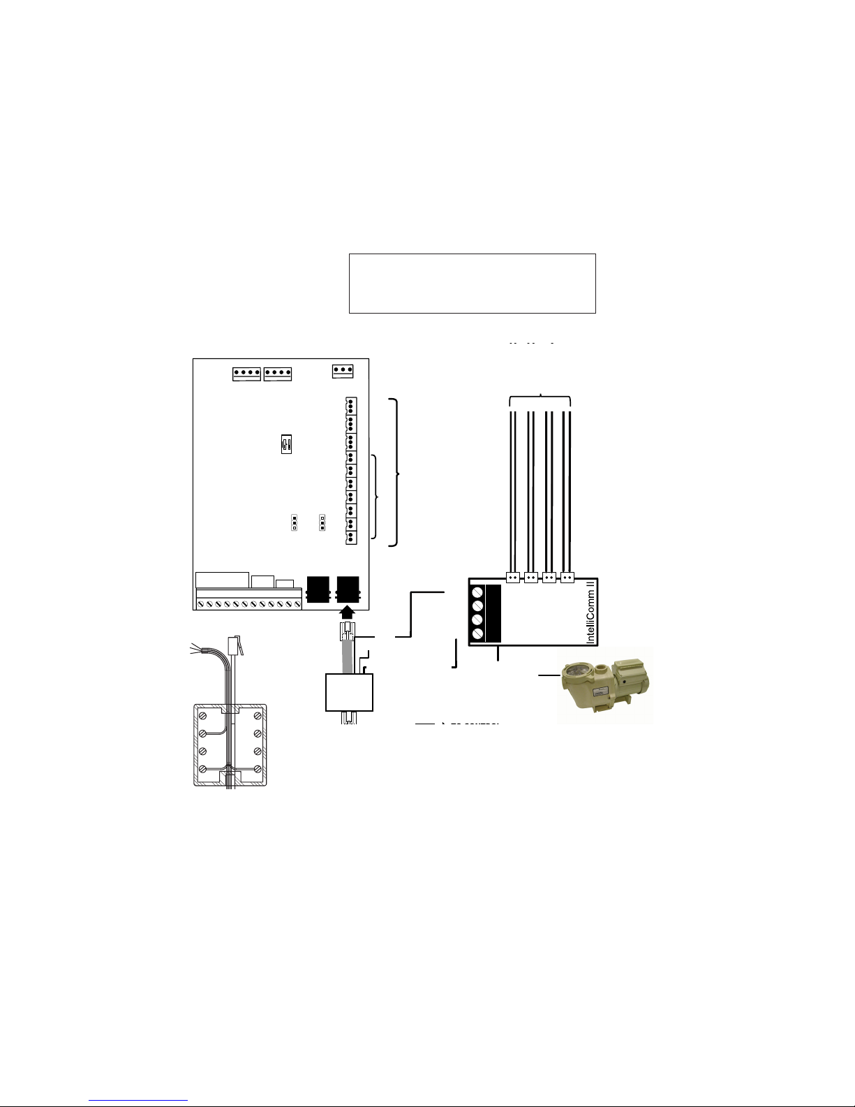
Connecting to a Compool®Control System ...................................................... 4
RYA-LX Harness (P/N RYALX) Accessory .................................................. 7
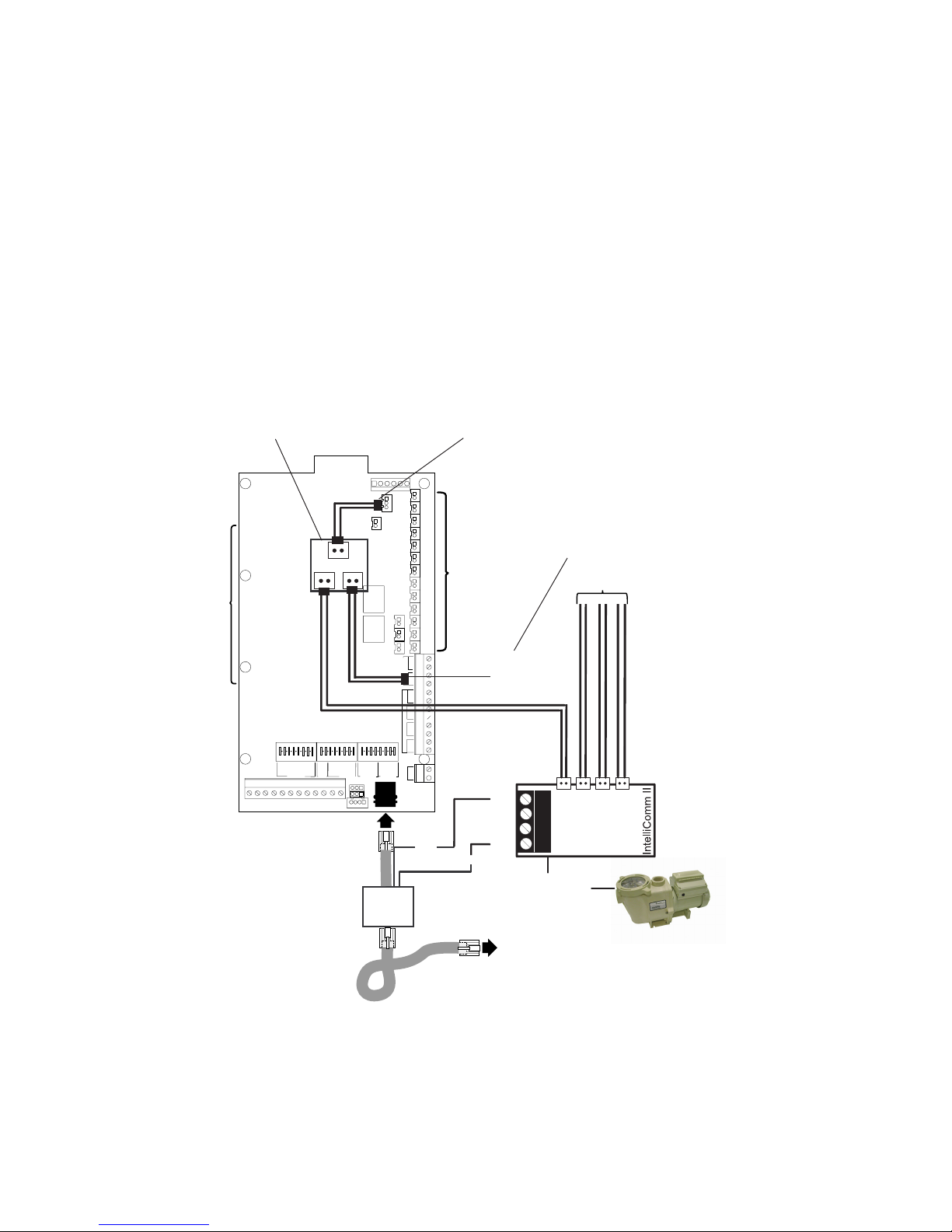
Connecting to a Jandy®AquaLink RS Control System .................................. 10
Connecting to a Hayward®Control System ....................................................12
Connecting to a Polaris®EOS Control System ...............................................14
Setting up an IntelliFlo®VF Pump with IntelliComm II .....................................16
Mounting the IntelliComm II Interface Adapter ............................................... 20
i
IMPORTANT SAFETY PRECAUTIONS
© 2009 Pentair Water Pool and Spa, Inc. All rights reserved.
1620 Hawkins Ave., Sanford, NC 27330 • (919) 566-8000
10951 West Los Angeles Ave., Moorpark, CA 93021 • (805) 553-5000 • (800) 831-7133
IntelliComm®, IntelliFlo®, IntelliPro®, IntelliTouch®, EasyTouch®, SunTouch®, Compool®, and Pentair Water
Pool and Spa® are trademarks and/or registered trademarks of Pentair Water Pool and Spa, Inc. and/or its
affiliated companies in the United States and/or other countries. Hayward®and ProLogic®are registered
trademarks of Hayward Industries Inc. Jandy®and AquaLink®are registered trademarks of Jandy
Industries Inc. Polaris®is a registered trademark of Zodiac Pool Systems, Inc. Unless noted, names and
brands of others that may be used in this document are not used to indicate an affiliation or endorsement
between the proprietors of these names and brands and Pentair Water Pool and Spa, Inc. Those names
and brands may be the trademarks or registered trademarks of those parties or others.
P/N 521033 - Rev C - 10/16/09
Before installing the IntelliComm®II Interface adapter , read
and follow all warning notices and instructions which are
included. Failure to follow safety warnings and instructions can result in severe
injury, death, or property damage. Call (800) 831-7133 for additional free copies
of these instructions.
Risk of electrical shock or electrocution:
The IntelliComm II Interface adapter must be installed by a
qualified electrician, according to the National Electrical Code
(including article 680-22) or Canadian Electrical Code
(including section 68) and local codes and ordinances. The
electrician should also consult the local building department
regarding local codes.
Technical Support: (800) 831-7133
Improper installation will create an electrical hazard which could result in death or
serious injury to pool users, installers, or others due to electrical shock, and may
also cause damage to property.
Always disconnect power to the pool pump at the circuit breaker before
servicing the pump. Failure to do so could result in death or serious injury to
serviceman, pool users or others due to electric shock.

IntelliComm II Interface Adapter Installation and User’s Guide
1
IntelliComm®II interface adapter kit contents
• IntelliComm II Interface Adapter
• Two mounting screws
• Mounting tape
• One Terminal Connector (RS-485 and IntelliComm II power connection)
• Compool RJ12 Adapter
• Four AUX cables (22 AWG)
• Installation and User’s Guide (this manual)
IntelliComm II interface adapter overview
The IntelliComm II interface adapter provides automatic control of IntelliFlo®VF ,
IntelliFlo VS and IntelliPro®pumps. IntelliComm II is compatible with IntelliTouch®,
EasyTouch®, SunTouch®, Compool®, Hayward®, Jandy®and Polaris®EOS control
systems. The IntelliComm II Interface adapter provides:
Four input (9-24V DC/AC) program terminals (GPM/RPM 1, 2, 3,
and 4) for connection to any available auxiliary relay, valve actuator or controlled
output circuit on the automation control system circuit board. Typically, GPM/RPM 1
connects to the output Filter Pump relay terminal plug. You can also connect to the
spa, pool electric heater, solar or 2-speed pump output circuit. Each of the four
inputs can be used to control the IntelliFlo pump's speed or flow.
Note: If more
than one terminal input is active, the highest input number (GPM/RPM 4) will
take priority regardless of the pump setting.
A four screw terminal connector for connection to the RS-485 IntelliFlo
communication cable and power source (9-24V DC) from the automation control
system circuit board.
Note: The IntelliComm II Interface adapter will always use ADDRESS 1 to
communicate with the IntelliFlo pump.
Note: The IntelliComm II Interface adapter can be used with IntelliTouch®,
EasyTouch®and SunTouch®systems, when additional pumps are required
beyond the normal system capacity.
Safety Devices: All required safety devices, such as the IntelliFlo
VS+ SVRS (Safety Vacuum Release System) pump, are unaffected when using
the IntelliComm II.
Selecting Flow Rates (GPM) for IntelliFlo VF
The IntelliFlo VF pump can be selected to run at a specific US gallons per minute
(GPM), for each external control input:
IntelliFloVF: 15 - 130 GPM
Selecting Pump Speeds (RPM) for IntelliFlo VS+ SVRS
and IntelliPro VS3050
The IntelliFlo VS+ SVRS, IntelliFlo VS 3050 and IntelliPro VS 3050 pump can be
selected to run at a specific speed (RPM), for each external control input:
IntelliFlo VS+ SVRS: 1100 - 3450 RPM
IntelliFlo VS 3050: 400 - 3450 RPM
IntelliPro VS 3050: 400 - 3450 RPM

IntelliComm II Interface Adapter Installation and User’s Guide
2
Connecting to IntelliComm II Input Program Terminals
There are four (two-wire) cables provided in kit for interface connections from the
automation control system circuit board, to the four IntelliComm II program (GPM /
RPM) input terminal (see page 3). The input terminal cable wires are not polarized.
Plugs/wires can be connected in any order.
Connecting IntelliComm II to a Valve Actuator
A Valve Actuator can be connected from the automation control system circuit
board to any one of the IntelliComm II input terminals (1-4) by splicing into the
valve actuator cable using the provided two-wire input terminal cable
(see page 3).
Connecting Power (9-24VDC) to IntelliComm II
Power to the IntelliComm II requires a 9-24VDC, 200mA power source, which
can be supplied from the automation control system circuit board or an
AC to DC power adapter. For VDC power connection on Compool, Jandy and
Hayward control systems, see pages 4 - 13.
Screw terminal: Connects to the pump via a two pin 50 ft.
communication cable (P/N 350122) provided with the pump.
Also connects to a 9-24VDC, 200mA power source (automa-
tion control system circuit board)
Four (9 - 24V DC/AC) input
terminals (GPM / RPM 1, 2, 3, 4):
Each input terminal connects to an
output relay or valve terminal on
the automation control system
circuit board via a two-pin AUX
cable.
Power LED on when power is applied.
IntelliComm II Interface Adapter Connections
IntelliComm II
Interface Adapter
LED on when power (9-24V DC) is
received from automation system.
1
2
3
4
IntelliFlo pump AC connection
If multiple pump speeds are required, the IntelliFlo pump must be wired to a
circuit breaker not to a relay.
Note: If the IntelliFlo pump is used in a commercial application or connected to
an Emergency Shut-Off switch, the pump must be connected to a relay for proper
Emergency Shut-Off operation.
Salt Chlorine System Connections
All Salt Chlorine Generator (SCG) units must be connected to the Filter Pump
relay output. If the Filter Pump relay output is being used for the IntelliComm II,
then a RYALX can be used if a SCG is present in the system. For more information
about using the RYALX see page 7.

IntelliComm II Interface Adapter Installation and User’s Guide
TO OPERATE THE INTELLIBRITE COLOR LIGHT SHOWS
3
Connecting IntelliComm II to IntelliFlo
Connection from IntelliComm II to an IntelliFlo VF or IntelliFlo VS pump is via
a 50 ft. RS-485 communication cable (P/N 350122), which is provided with
the pump.
Connecting the IntelliFlo Pump to IntelliComm II RS-485 Terminal
Connect the YELLOW and GREEN wire from the IntelliFlo communication
cable to the YELLOW and GREEN RS-485 screw terminals on the
IntelliComm II interface adapter as shown below.
IntelliComm II to IntelliFlo Pump and Pentair Water Pool and Spa
Automation Control Circuit Board Connection Diagram
RS-485 COMMUNICATION
CABLE (22 AWG)
PWR
BLK
YLW
GRN
RED
GPM/RPM 1
9 - 24V DC/AC
YLW
GRN
RELAY 4
RELAY 3
RELAY 2
RELAY 1
9 - 24V DC/AC
PentairWater Pool and Spa
Automation Control Board
GND
RED
BLK
PWR
GND
GPM/RPM 2
GPM/RPM 3
GPM/RPM 4
(used with SunTouch,EasyTouch
and IntelliTouch)
(PROGRAM 1)
(PROGRAM 2)
(PROGRAM 3)
(PROGRAM 4)
VLV A VLV B
INTAKE RTRN
VLV A
IntelliComm II
Automation
Circuit Board
9 - 24VDC
WHITE
RED
BLK
or
Note: Connect GPM/RPM 1, 2, 3, and 4 to any
control output or auxiliary relay circuit (RELAY
1-4) on the automation circuit board. Typically,
GPM/RPM 1 connects to Filter Pump.
If more
than one terminal input is active, the highest
input number (GPM/RPM 4) will take priority
regardless of the pump setting.
Note: The black wire
must be used.
Choosing either the
Red or White wire
will depend on the
direction that the
actuator needs to
rotate to the spa.

IntelliComm II Interface Adapter Installation and User’s Guide
4
Connecting to a Compool®Control System
Connection from IntelliComm II to a Compool control system utilizes the RJ12
adapter (provided in the kit), and the IntelliFlo RS-485 communication cable
(provided with the pump).
Compool Models Compatible with IntelliComm II (see page 6 and 7)
Compool CP-3xxx series, CP-2000 and Time Master, CP-1000, CP-2020, Swim
Master LX-20, LX-42, CP-2020, LX-100, LX-80 Commercial and CP-100 control
systems. Note: IntelliComm II does not support the LX-820 Commercial system.
Compool Models Compatible with IntelliComm II
(Using an External 9 VDC 200mA AC Power Adapter)
The following Compool models are compatible with IntelliComm II using an
external 9 VDC, 200mA AC power adapter: Compool CP-30, LX-220, LX-40.
Accessing the Compool Circuit Board
The Compool control system circuit board is located in the power center. Refer
to the Compool control system owner’s manual for access information.
Connecting power to the IntelliComm II from a Compool
CP3xxx circuit board (see page 5 and 7)
1. Connect RJ12 adapter power wires (9-24V DC/AC): From the RJ12
adapter, connect the BLACK wire and RED wire to the RS-485 GND
(BLACK) and PWR (RED) terminal respectively. NOTE: For LX-100:
Connect the YELLOW wire from RJ12 to IntelliComm II Red (PWR)
screw terminal. Note: To avoid circuit board damage, DO NOT
connect the RED and YELLOW wires together to Red (PWR)
terminal, leave RED UNCONNECTED (see page 6).
2. Connect RJ12 adapter cable plug to the Compool COM PORT:
Disconnect the Compool control panel RJ12 plug from the Compool
circuit board COM Port and connect it to the RJ12 adapter (provided).
Connect the RJ12 adapter plug into the COM Port (use black plug for
LX-100) on the Compool circuit board (see page 5).
3. Connecting AUX cables: Choose the functions you wish to control on
the Compool system. Connect the auxiliary cables (provided in kit) from
the IntelliComm II input terminals (GPM/RPM 1, 2, 3, 4) to the auxiliary
connector on the Compool circuit board. Typically, GPM/RPM 1 input
terminal, connects to Compool FILTER PUMP output terminal. Choose
the other functions on the Compool board and connect them to
GPM/RPM 2, 3, and 4 input terminals.
4. Connecting IntelliComm II to IntelliFlo: For IntelliComm II to IntelliFlo
wiring information, see page 3.
6. Mounting the IntelliComm II (see page 20).
7. Setting up IntelliFlo speeds and flow rates (see page 16).
Always disconnect AC POWER to the LOAD CENTER at the circuit
breaker. Also, disconnect AC power to the PUMP before installing the
IntelliComm II interface adapter. Failure to do so could result in death
or serious injury to the service person, pool users or others due to
electric shock. Read all SAFETY PRECAUTIONS on page i before
starting.

IntelliComm II Interface Adapter Installation and User’s Guide
5
1234567
ON
81234567
ON
81234567
ON
8
CAUTION: DO NOT SHORT PINS OF RELAY SOCKETS
GND
HLMP
HBST
SPA
POOL
REM1
REM2
REM3
REM4
REM5
REM6
1810 24
PART# PC-LX3830COMPOOL 11010B
SPA
2SPD
SFLT
PFLT
AUX1
AUX2
AUX3
AUX4
AUX5
AUX6
FREEZE I/L SYST
SPC FNCT
FDEL
CLNR
MANHT
SSOL
SHPMP
PSOL
PHPMP
FLRCL
DIM3
DIM4
B/W
SHEAT
SAUX2
PHEAT
PAUX1
DIM3DIM4
POOL
2SPD
PHONE
COM PORT
SPA WTRPOOL WTR
GRN
RED
GRN
RED
GRN
RED
GAS HEATERS
SPA
FLTR
POOL
FLTR
AUX3
AUX4
AUX5
AUX6
POOL SOL
AUX2
AUX1
HI SPD
GRN
RED
FREEZE
SENSOR
POOL SPA
B/W
SPA
EHTR
SPA
SOL
POOL
EHTR
POOL
SOL
SPA SOL
GRN
RED
TEMPERATURE SENSORS
SPA
HEAT
PHONE CONTROLS
POOL
FLR
CLN
AUX
VLV
CNTRL
AUX
VLV
TO CONTROL
PANEL
RED
BLK
GRN
YLW
RED
PRGM 4
PRGM 3
PRGM 2
PRGM 1
9 - 24V DC/AC
RS485
RS-485
PIN 3 (GRN)
PIN 2 (YLW)
TO PUMP
RJ12
ADAPTER
TO COM PORT
IntelliFlo pump
GND
PWR
BLK
CHOOSE FUNCTION
(for connection to IntelliComm II)
COM
PORT
CP3xxx
YLW
RED
BLK
RJ12
Adapter
Wiring
Diagram
Note: Using a RYALX Harness
(for Compool CP-38xx Systems): For the Compool SOLAR system, connect the
RYALX harness cable plug to the SOLAR socket, then connect the IntelliComm II pump
speed plug and the VALVE cable plug to the RYALX board. The RYALX can be used for
any output.
Note: The Spa output plug on the Compool circuit board can be used for direct
IntelliComm II connection, instead of splicing into the valve output cable.

IntelliComm II Interface Adapter Installation and User’s Guide
6
RELAY CONNECTIONS
DO NOT SHORT THESE PINS
FLTR
SPA
EHTR
AUX3
VLV
AUX1
AUX2
CLNR
AUX
VLV
VLV
RET
24
YES
DELAY
18 0
INT
WTRFL
12
ON
AUX1
NO
MOTOR SWITCH
FLTR TIMER
MOTOR SWITCH
CLNR TIMER
SILVER
12
+15
GND
AUX1
SPA
AUX3
AUX2
CSP
GAS HTR
SLMP
REMOTE SWITCHES
YRG
CLNR
AUX VLV
CONTROLLED BY
AUX3
JP16 JP17
GRN RED
TEMP
SENSOR
COM
PORT
TO CONTROL
RED NOT CONNECTED
BLK
GRN
YLW
RED
PRGM 4
PRGM 3
PRGM 2
PRGM 1
9 - 24VDC
RS485
RS-485
PIN 3 (GRN)
PIN 2 (YLW)
TO PUMP
RJ12
ADAPTER
TO COM PORT
(LX100 use black plug)
IntelliFlo pump
LX-100 ONLY (YLW)
GND
PWR
Only connect YELLOW
wire for LX-100. Do not
connect red and yellow
wires together.
BLK
CHOOSE FUNCTION
(for connection to IntelliComm II)
LX100 Motherboard
Note: Use a RYALX Harness (P/N RYALX) If
the circuit board relay output is in use and the
IntelliComm II AUX cable needs to share the
socket output.
YLW
RED
BLK
RJ12
Adapter
Wiring
Diagram
Connecting power to the IntelliComm II from a Compool
LX100 circuit board

IntelliComm II Interface Adapter Installation and User’s Guide
RYALX Harness (P/N RYALX) Accessory
(For use with Compool CP-38xx Systems)
The RYALX harness (y-adapter) allows any one output circuit to operate two relay
circuits. For example, to free up an additional connection on the Compool SOLAR
system, connect the RYALX harness cable plug to the SOLAR socket, then
connect the IntelliComm II pump speed plug and the VALVE cable plug to the
RYALX board. The RYALX can be used for any output.
The example connection diagram below shows how to share the Aux Valve
Control using solar. The signal to tell solar to turn on, comes from the solar socket
located below the HTR socket. Then the AUX VLV control and the speed of the
pump now responds to that signal.
1234567
ON
81234567
ON
81234567
ON
8
CAUTION: DO NOT SHORT PINS OF RELAY SOCKETS
GND
HLMP
HBST
SPA
POOL
REM1
REM2
REM3
REM4
REM5
REM6
1810 24
PART# PC-LX3830COMPOOL 11010B
SPA
2SPD
SFLT
PFLT
AUX1
AUX2
AUX3
AUX4
AUX5
AUX6
FREEZE I/L SYST
SPC FNCT
FDEL
CLNR
MANHT
SSOL
SHPMP
PSOL
PHPMP
FLRCL
DIM3
DIM4
B/W
SHEAT
SAUX2
PHEAT
PAUX1
DIM3DIM4
POOL
2SPD
PHONE
COM PORT
SPA WTRPOOL WTR
GRN
RED
GRN
RED
GRN
RED
GAS HEATERS
SPA
FLTR
POOL
FLTR
AUX3
AUX4
AUX5
AUX6
POOL SOL
AUX2
AUX1
HI SPD
GRN
RED
FREEZE
SENSOR
POOL SPA
B/W
SPA
EHTR
SPA
SOL
POOL
EHTR
POOL
SOL
SPA SOL
GRN
RED
TEMPERATURE SENSORS
SPA
HEAT
PHONE CONTROLS
POOL
FLR
CLN
AUX
VLV
CNTRL
AUX
VLV
TO CONTROL
PANEL
RED
BLK
GRN
YLW
RED
PRGM 4
PRGM 3
PRGM 2
PRGM 1
9 - 24V DC/AC
RS485
RS-485
PIN 3 (GRN)
PIN 2 (YLW)
TO PUMP
RJ12
ADAPTER
TO COM PORT
IntelliFlo pump
GND
PWR
BLK
CHOOSE FUNCTION
(for connection to IntelliComm II)
COM
PORT
RYA-LX
COMPOOL
7
CP-38xx Motherboard
AUX VLV
SOLAR
PUMP
RYALX Circuit board
This output is
used for both
the 3-way
valve
and a solar
booster pump
if required.

IntelliComm II Interface Adapter Installation and User’s Guide
LX-42
8
Connecting Power to IntelliComm II from Compool Circuit
Board
To power the IntelliComm II requires a two wire connection from the Compool
circuit board to the IntelliComm II circuit board (as shown below). For Compool to
IntelliComm II auxiliary cable connection information, see Connecting AUX
cables, on page 4.
To IntelliFlo pump
BLK (GND)
YLW
GRN
RED (9-24V DC)
PRGM 4
PRGM 3
PRGM 2
PRGM 1
9 - 24V DC/AC
PWR
GND
From Compool circuit board
Connect to Compool circuit board
(see page 4)
Choose the function on the
Compool circuit board
RED (24 VDC)
BLACK (GND)
Always disconnect AC power to the LOAD CENTER at the circuit
breaker. Also, disconnect AC power to the PUMP before installing the
IntelliComm II interface adapter. Failure to do so could result in death
or serious injury to the service person, pool users or others due to
electric shock. Read all SAFETY PRECAUTIONS on page i before
starting.

IntelliComm II Interface Adapter Installation and User’s Guide
9
BLACK (GND)
Swim Master (LX20)
CP2000 and Time Master (LX10)
BLACK (GND)
RED (24 VDC)
BLACK
(GND)
RED (24 VDC)
CP1000
RED (24 VDC)
BLACK (GND)
RED (24 VDC)
CP2020
BLACK (GND)
RED (24 VDC)
SP100 (LX36)

IntelliComm II Interface Adapter Installation and User’s Guide
10
Connecting to a Jandy®AquaLink® RS Control System
Access Jandy control system circuit board
The Jandy control system circuit board is located in the load center. Refer to the
Jandy control system owner’s manual for access information.
Connect power to the IntelliComm II (9-24 VDC) from Jandy circuit board
1. Connect the GREEN (-) wire and the RED (+) wire from the Jandy
RS-485 screw terminal, to the GND and PWR terminal respectively, on
the IntelliComm II RS-485 screw terminal (see page 8).
Connect AUX cables
2. Connect the auxiliary cables (provided in kit) from the IntelliComm II
input terminals GPM/RPM 1, 2, 3, and 4 to any control output or
auxiliary relay circuit on the Jandy circuit board. Typically, GPM/RPM 1
connects to the output Filter Pump relay terminal plug. However, Jandy
auxiliary relay circuits can be connected to any of the four input
terminals for custom pump speed control.
NOTE: If more than one
terminal input is active, the highest input number (GPM/RPM 4) will
take priority regardless of the pump setting.
3. Connect IntelliComm II to IntelliFlo
For IntelliComm II to IntelliFlo wiring information, see page 3.
4. Mounting the IntelliComm II (see page 20).
5. Setting up IntelliFlo speeds and flow rates (see page 16).
Always disconnect AC power to the LOAD CENTER at the circuit
breaker. Also, disconnect AC power to the PUMP before installing the
IntelliComm II interface adapter. Failure to do so could result in death
or serious injury to the service person, pool users or others due to
electric shock. Read all SAFETY PRECAUTIONS on page i before
starting.

IntelliComm II Interface Adapter Installation and User’s Guide
11
JANDY RS circuit board
auxiliary connections
RS-485 COMMUNICATION
CABLE (22 AWG)
9-24V DC/AC
4321
RED
BLK
YEL
GRN
S1
S2
RESET
SERVICE
TIMEOUT
FILTERPUMP
AUX1
AUX2
AUX3
AUX4
AUX5
AUX6
AUX7
RS6& RS8 ONLY
RS8ONLY
HEATER SOLAR
POOLMODE
SPAMODE
SPADRAIN
SPAFILL
AUTO
654321
10987654321
4321 4321
230VAC power
to pump
RELAY 1
RELAY 2
RELAY 3
9 - 24VDC
Red
Terminal
Bar
Jandy RS Power Center
IntelliComm II
(mounted inside
low voltage compartmen
t
of Power Center)
RS485
YLW
GRN
BLK
YLW
GRN
RED
PRGM 4
PRGM 3
PRGM 2
PRGM 1
9 - 24V DC/AC
GND
PWR
GND
CHOOSE FUNCTION
(for connection to IntelliComm II)
RELAY 4
IntelliComm II to Jandy AquaLink Control System Connection Diagram
Note: Connect GPM/RPM 1,
2, 3, and 4 to any control
output or auxiliary relay
circuit (RELAY 1-4) on the
Jandy circuit board. Typically,
GPM/RPM 1 connects to
Filter Pump.
If more than
one terminal input is
active, the highest input
number (GPM/RPM 4) will
take priority regardless of
the pump setting.
Note: The Spa output plug on the Jandy circuit board can be used for direct
IntelliComm II connection, instead of splicing into the valve output cable.

IntelliComm II Interface Adapter Installation and User’s Guide
Connecting to a Hayward®Pro Logic®Control System
The following describes how to connect IntelliComm II to a Hayward Pro Logic®
series control system (see page 13 for connection diagram).
Access the Hayward Pro Logic Circuit Board
The Hayward control system circuit board is located in the load center. Refer to
the Hayward control system owner’s manual for access information.
Connect power to the IntelliComm II (9-24V DC) from Hayward Circuit Board
1. Connect the GREEN (-) wire and the RED (+) wire from the Hayward
screw terminal (RS-485), to the GND and PWR terminal respectively,
on the IntelliComm II RS-485 screw terminal (see page 13).
Connect AUX cables (Disconnect AC power to the PUMP and Controller)
2. Cut one plug off each of the provided four auxiliary cables. Strip back
the ends of the wires.
3. Remove the relay bracket(s) to access relays: In the Hayward load
center, remove the two screws securing the upper and lower relay
bracket and remove the brackets.
4. Attach wires to the FILTER PUMP relay screws terminals: Loosen
the two top relay terminal screws with attached wires. Using the
provided auxiliary cable (see step 1), carefully wrap the ends of each
wire under the screw terminals. Tighten the screws to secure the wires
in place. Wires are not polarized; connect wires to either relay terminal.
5. Repeat Step 3: Splice the cable wires into any control output or
auxiliary circuit relay terminals on the Hayward circuit board.
6. Reinstall the relay bracket(s) in the load center and secure with the
retaining screws.
7. Connect IntelliComm II to IntelliFlo
For IntelliComm II to IntelliFlo wiring information, see page 3.
8. Mounting the IntelliComm II (see page 20).
9. Setting up IntelliFlo speeds and flow rates (see page 16).
12
Always disconnect AC power to the LOAD CENTER at the circuit
breaker and disconnect AC power to the PUMP before installing the
IntelliComm II interface adapter. Failure to do so could result in death
or serious injury to the service person, pool users or others due to
electric shock. Read all SAFETY PRECAUTIONS on page i before
starting.

IntelliComm II Interface Adapter Installation and User’s Guide
9 - 24V DC/AC
9 - 24VDC
13
IntelliComm II to Hayward Pro Logic Control System Connection Diagram

IntelliComm II Interface Adapter Installation and User’s Guide
14
Connecting to a Polaris®EOS Control System
The following describes how to connect IntelliComm II to a Polaris®EOS control
system (see page 15 for connection diagram).
Connecting Power to IntelliComm II from Polaris Circuit Board
To power the IntelliComm II requires a two wire connection from the Polaris circuit
board to the IntelliComm II circuit board (as shown on page 15).
Access the Polaris Circuit Board
The Polaris control system circuit board is located in the load center. Refer to the
Polaris EOS control system owner’s manual for access information.
Connect power to the IntelliComm II (9-24 VDC) from Polaris circuit board
1. Connect the GREEN (-) wire and the RED (+) wire from the Polaris 24
VDC output screw terminal, to the GND and PWR terminal
respectively, on the IntelliComm II RS-485 screw terminal (see page
15).
Connecting AUX cables
2. Connect the auxiliary cables (provided in kit) from the IntelliComm II
input terminals GPM/RPM 1, 2, 3, and 4 to any control output or
auxiliary relay circuit on the Polaris circuit board. Typically, GPM/RPM 1
connects to the output Filter Pump relay terminal plug (HP4). However,
Polaris auxiliary relay circuits (HP1 - HP6) can be connected to any of
the four input terminals for custom pump speed control.
NOTE: If more
than one terminal input is active, the highest input number (GPM/
RPM 4) will take priority regardless of the pump setting.
3. Connect IntelliComm II to IntelliFlo
For IntelliComm II to IntelliFlo wiring information, see page 3.
4. Mounting the IntelliComm II (see page 20).
5. Setting up IntelliFlo speeds and flow rates (see page 16).
Always disconnect AC power to the LOAD CENTER at the circuit
breaker and disconnect AC power to the PUMP before installing the
IntelliComm II interface adapter. Failure to do so could result in death
or serious injury to the service person, pool users or others due to
electric shock. Read all SAFETY PRECAUTIONS on page i before
starting.

IntelliComm II Interface Adapter Installation and User’s Guide
15
To IntelliFlo pump
BLK (GND)
YLW
GRN
RED (9-24 VDC)
RELAY4
RELAY3
RELAY2
RELAY1
9 - 24V DC/AC PWR
GND
From Polaris circuit board
Connect to Polaris circuit board
Choose the function on the Polaris circuit board (HP1-HP8, VLV1 -VLV 6)
Polaris EOS Control System Load Center
24 VDC (To power IntelliComm II)
From 24 VDC to RED (PWR) and
BLK (GND) on IntelliComm II board

IntelliComm II Interface Adapter Installation and User’s Guide
16
Setting up an IntelliFlo VF Pump with IntelliComm II
The IntelliFlo VF pump can operate with all of its stand alone features if desired.
For example the pump can run filter cycles, egg timer features 1 and 2 and time
of day scheduling of features 3-9. If IntelliComm II sends the pump a command
when the pump is running the filter cycle or features 3-9, the IntelliComm II
command takes priority regardless of flow rate. IntelliComm II will not interrupt
nor take priority over Features 1 or 2.
For the IntelliFlo VF to accept a command from the IntelliComm II the pump must
be in the “Running” mode. To place the IntelliFlo VF in “Running” mode, press
the Filter mode button, then press the Start/Stop button. The led above the
Start/Stop button must be lit for the IntelliFlo VF to accept commands from the
IntelliComm II.
The default “Filter” cycle time in the IntelliFlo VF is from 9 AM to 9 PM. Since the
IntelliFlo VF must be in the “Filter” mode, running Schedules, (LED above Start/
Stop button lit) to accept commands from IntelliComm II, it will run its default
filtration schedule first. If you want the pump to only run when it receives
commands from IntelliComm II, program its “Filter” mode with the same start and
stop times. For example program Cycle 1 in the “Filter” menu to “Start” cycle one
at 9 AM and “Stop” cycle one at 9 AM. This will cause the pump to not run its
filter cycle. This is done on the IntelliFlo keypad under Menu, Filter. Address 1,
is the default address for the IntelliFlo VF. The IntelliComm II will only
communicate with address 1. The pump’s “Address” setting is the first menu
item under “Pool Data”.
Programming Flows into the IntelliFlo VF
1. Press the Menu button.
2. Press the down arrow until Ext. Ctrl. (External Control is displayed).
3. Press the Select button to go Ext. Ctrl. (Program 1 is displayed).
4. Press the Select Button (Enabled, Activation is displayed).
5. Press the down arrow. (Program 1, 30 GPM, Set Flow, is displayed. The
Program 1 flow rate will run when PRGM 1 is activated on the
IntelliComm II control board.
6. To change this flow rate press the “Select” button. The flow rate can be
adjusted from 15 gpm to 130 gpm.
7. The cursor will highlight the one's digit column. Press the left and right
arrows to move the cursor and the up and down arrows to change the
number.
8. Press the Enter Button to save.
9. Press the down arrow until “Time Delay Stop” is displayed. Time Delay
Stop is used to control the pump to run the Program speed for an
additional amount of time after the IntelliComm II turns off its run
command. This is often used for a heater cool down.
10. Press Select to highlight the cursor, use the left and right arrows to
move the cursor and the up and down arrows to change the number.
11. Press Enter to save.
12. Press Escape to Exit. The display shows Program 1. Press the down
arrow to get to Program 2 and follow the same instructions to program.
For more information about programming the pump, refer to the
IntelliFlo VF Installation and User’s Guide (P/N 353850).

IntelliComm II Interface Adapter Installation and User’s Guide
17
Setting up an IntelliFlo VS or IntelliPro VS
The IntelliFlo VS pump Speeds 1, 2, 3 and 4 correspond to Prgm (Program) 1, 2,
3 and 4 on the IntelliComm II circuit board. To program speed one on the
IntelliFlo VS. Press the “Speed 1” button. Press the Start button. To increase the
speed of “Speed 1” press the up arrow button. Each press of the up arrow will
increase the RPM by 10 RPM increments. Pressing the down arrow will
decrease the RPM by 10 RPM. When the desired speed is found, press and
hold down the “Speed 1” button and the new speed will be locked in. This new
speed will be the speed that the pump will run when “Prgm 1” is activated on the
IntelliComm II. The speed can be adjusted from 400 RPM to 3450 RPM.
Note: If the IntelliFlo VS pump is turned on manually by pressing a Speed
button and the Start button, it will run the speed that was pressed and the LED
above this button will be illuminated. If it then gets a command to run a speed
from the IntelliComm II, it will run the new commanded speed and the LED
above the new speed will be illuminated. When the command from the
IntelliComm II has stopped, the pump will go back to running the manually
pressed speed.
Note: If the IntelliComm II has switched on the IntelliFlo VS and it is running a
speed and you manually adjust the pump speed using the speed buttons on the
pump, you must then manually switch the pump OFF, this turns off the manually
manipulated speed and allows the IntelliComm II to take command and switch
the pump back on to run at the commanded speed. If, after manipulating the
keypad, the pump is not manually turned off by pressing the Stop button the
pump will continue to run after the IntelliComm II command is stopped.
Unlike the VF, the IntelliFlo VS does not have to be in the “Running” mode to
accept commands from an IntelliComm II. The power must be on (Green LED lit)
on the IntelliComm II to accept commands.
Setting up an IntelliFlo VS+SVRS
The IntelliFlo VS+ SVRS is programmed in a similar way to the IntelliFlo VF.
Speeds for each program number are set up under the menu item “Ext. Ctrl.”
(External Control).

IntelliComm II Interface Adapter Installation and User’s Guide
18
IntelliFlo Pump Warnings and Alarm Conditions
The IntelliFlo VS-3050 alarms and warnings are indicated by flashing LEDs on
the control panel. For example, if a “Drive Temperature” warning occurs, the LED
will blink two times, then Off, then blink two times. This sequence is repeated until
the condition is cleared.
•Warning condition: If a warning condition occurs the pump will
be continue to run but at a reduced speed. The Green LED
executes a sequence of blinks to indicate which alarm or
warning has occurred.
•Alarm condition: If an alarm condition occurs the pump will drive
stop running. The red LED flashes continuously to indicate the
presence of an alarm. The alarm LEDs will reset when the
condition clears.
Programming IntelliFlo VS+ SVRS Speeds
Press the menu button. Press the down arrow until “Ext Ctrl.” is displayed.
Follow the instructions as described on page 10 for the IntelliFlo VF (steps 1
through 12). However there is one difference. The IntelliFlo VS+SVRS does
not have any default “Schedules” so it is not necessary to deactivate any
schedules so it will only run commands from the IntelliComm II. But, just like
the IntelliFlo VF it can be programmed to run scheduled flows and when it
gets a command from IntelliComm II to run a program the IntelliComm II
program will take priority.
Note: If more than one terminal input is activated on the IntelliComm II the
highest number input will take priority, regardless of the pump setting. For
example: If program 1 and program 3 are activated on the IntelliComm II
The pump will run program 3, regardless of speed, flow or order of activa-
tion.
When a command to run is sent from the IntelliComm II to the VS+SVRS the
pump’s display will show “Running Prog. 1” and the countdown timer on the
IntelliFlo VF display will show 00:01.
CAUTION: When performing maintenance on the system or the pump
switch the power to the pump off at the circuit breaker. This will ensure that
the pump does not switch on from remote operation or run a schedule.
Table of contents