PERDIX SHEARWATER User manual

Operating Instructions

Operating Instructions
Page 2 RevA
Table of Contents
Table of Contents������������������������������������������������������������������ 2
Conventions Used in this Manual ��������������������������������������������������������� 3
1. Introduction...........................................................4
1�1� Features ��������������������������������������������������������������������������������������������������� 4
2. Covered by this Manual....................................... 5
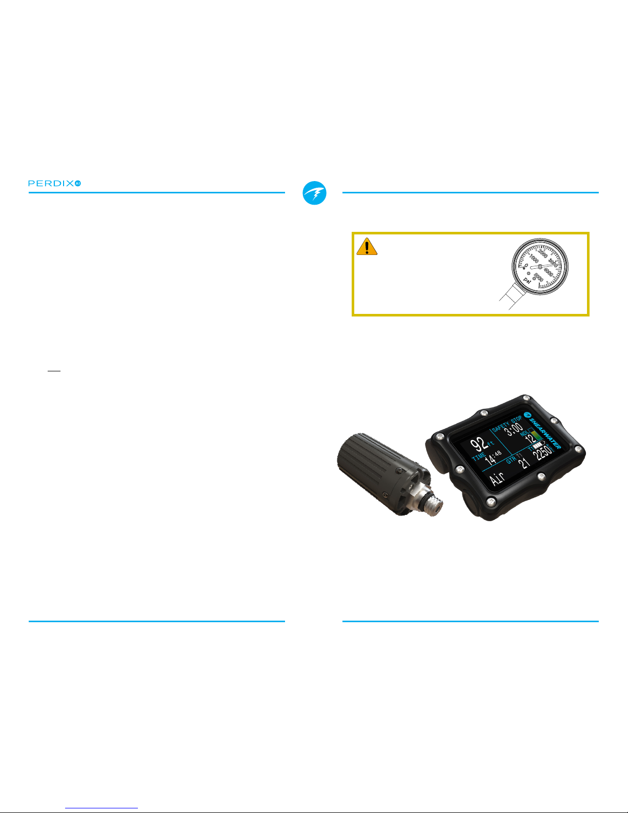
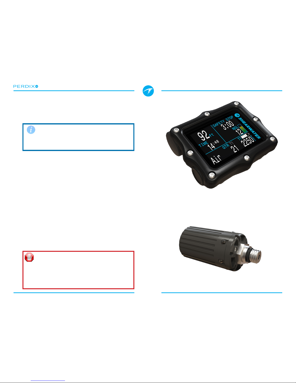
3. What is AI?............................................................ 5
4. Getting Started / Basic Setup ........................... 6
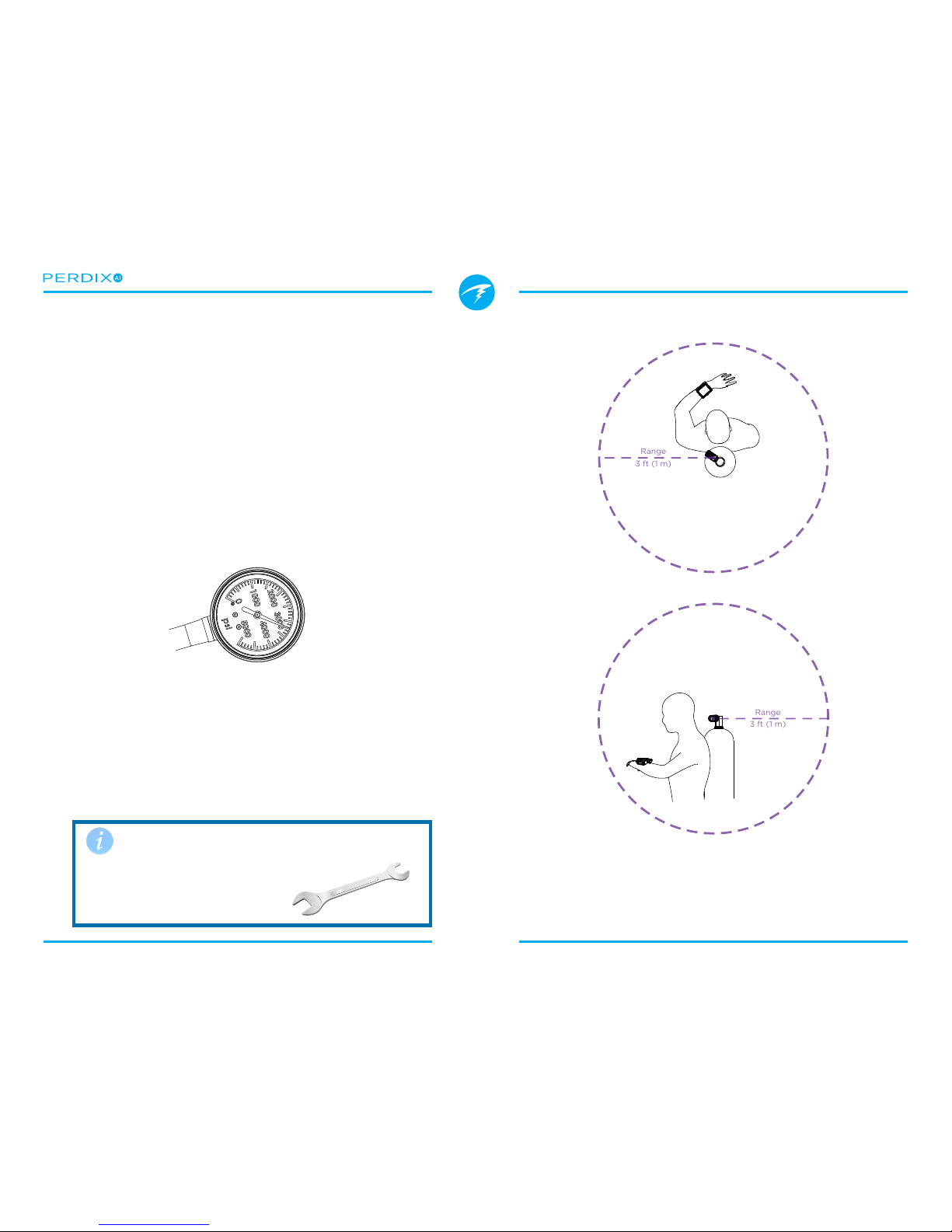
4�1� Install the Transmitter������������������������������������������������������������������������ 6
4�2� Turn On the Transmitter ������������������������������������������������������������������ 7
4�3� Turn Off the Transmitter������������������������������������������������������������������ 7
4�4� Enable AI on the Perdix ������������������������������������������������������������������ 7
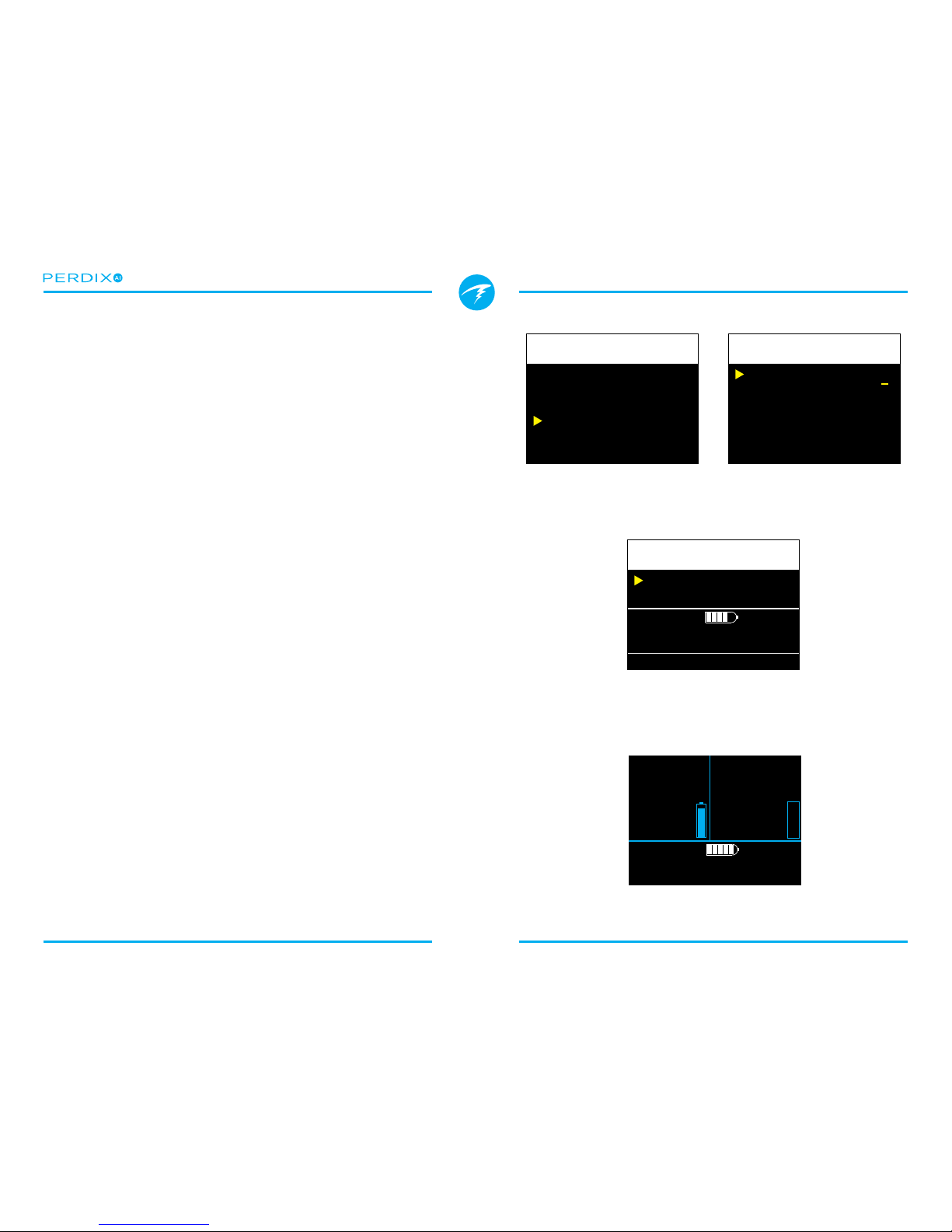
4�5� Pair the Transmitter �������������������������������������������������������������������������� 8
4�6� Add an AI display to the main screen ��������������������������������������� 8
4�7� Ready to Dive �������������������������������������������������������������������������������������� 8
5. AI Menus................................................................ 9
5�1� AI Setup �������������������������������������������������������������������������������������������������� 9
AI Mode������������������������������������������������������������������������������������������ 9
GTR Mode������������������������������������������������������������������������������������ 10
Units ��������������������������������������������������������������������������������������������� 10
T1/T2 Setup ��������������������������������������������������������������������������������� 10
5�2� T1/T2 Setup ���������������������������������������������������������������������������������������� 10
Serial # ����������������������������������������������������������������������������������������� 10
Rated Pressure ���������������������������������������������������������������������������� 11
Reserve Pressure ������������������������������������������������������������������������ 11
Unpair������������������������������������������������������������������������������������������� 11
6. AI Displays ...........................................................12
6�1� Adding to a configurable location�����������������������������������������������12
6�2� Viewing on the bottom info line �������������������������������������������������13
6�3� T1/T2 Pressure Display��������������������������������������������������������������������14
6�4� GTR Display ����������������������������������������������������������������������������������������14
6�5� SAC Display�����������������������������������������������������������������������������������������15
6�6� Mini Combination Display��������������������������������������������������������������15
7. How SAC and GTR are calculated.................... 16
7�1� SAC calculations ���������������������������������������������������������������������������������16
SAC vs RMV �������������������������������������������������������������������������������� 16
Why SAC instead of RMV? ���������������������������������������������������������� 16
SAC Formula�������������������������������������������������������������������������������� 16
Calculating RMV from SAC - Imperial units ��������������������������������� 16
Calculating RMV from SAC - Metric units ������������������������������������ 16
7�2� GTR calculations ��������������������������������������������������������������������������������17
Why aren’t safety stops included? ����������������������������������������������� 17
Why is GTR limited to one tank and no deco?����������������������������� 17
No compensation for Ideal Gas Law deviations��������������������������� 17
8. Troubleshooting..................................................18
8�1� Warning and error displays ������������������������������������������������������������18
8�2� Connection problems����������������������������������������������������������������������18
9. Storage and Maintenance................................. 19
9�1� Transmitter Battery Replacement �����������������������������������������������19
10. Servicing............................................................ 19
Glossary ................................................................... 19
Specifications .........................................................20
FCC Warning��������������������������������������������������������������������������������������������� 20

Operating Instructions
Page 3 RevA
DANGER
This computer is capable of calculating deco stop requirements�
These calculations are at best a guess of the real physiological
decompression requirements� Dives requiring staged
decompression are substantially more risky than dives that stay
well within no-stop limits�
Diving with rebreathers and/or diving mixed gases and/or
performing staged decompression dives and/or diving in
overhead environments greatly increases the risk of scuba
diving.
You really are risking your life with this activity.
WARNING
This computer has bugs� Although we haven’t found them all
yet, they are there� It is certain that there are things that this
computer does that either we didn’t think about, or planned for
it to do something dierent. Never risk your life on only one
source of information� Use a second computer or tables� If you
choose to make riskier dives, obtain the proper training and
work up to them slowly to gain experience�
This computer will fail� It is not whether it will fail but when it will
fail� Do not depend on it� Always have a plan on how to handle
failures� Automatic systems are no substitute for knowledge and
training�
No technology will keep you alive� Knowledge, skill, and
practiced procedures are your best defense (except for not
doing the dive, of course)�
Conventions Used in this Manual
These conventions are used to highlight important information:
INFORMATION
Information boxes contain useful tips for getting the
most out of your Perdix AI�
CAUTION
Caution boxes contain important instructions on
operating the Perdix AI�
WARNING
Warning boxes contain critical information that may
aect your personal safety.

Operating Instructions
Page 4 RevA
1. Introduction
The Shearwater Perdix AI is an advanced dive computer for
all types of diving� The Air Integration (AI) feature adds the
ability to wireless monitor the pressure of one or two scuba
tanks�
This manual only covers operation of the AI feature� Please
see the Perdix manual for full operating instructions of the
dive computer features�
Please take the time to read this manual� Your safety may
depend on your ability to read and understand the AI displays�
Do not use this manual as a substitute for proper dive training
and never dive beyond your training� What you don’t know
can hurt you�
1.1. Features
• Wireless pressure monitoring of 1 or 2 scuba tanks�
• Units in PSI or Bar�
• Flexible display setup�
• Optional Gas Time Remaining (GTR) and Surface Air
Consumption (SAC) rate based on one of the tanks�
• Logging of pressure, GTR, and SAC values at 10
second intervals�
• Average SAC of last dive displayed on surface�
• Warnings when reserve and critical pressures reached�
• Available in all modes (OC Rec, OC Tec, CC/BO, and
Gauge)
Use a backup analog SPG
Always use a backup analog
submersible pressure gauge as a
redundant source of gas pressure
information�
FIGURE 1 The Perdix AI transmitter and handset

Operating Instructions
Page 5 RevA
2. Covered by this Manual
This manual only covers operation of the wireless air
integration (AI) feature of the Perdix dive computer�
3. What is AI?
AI stands for Air Integration� On the Perdix AI, this refers to a
system that uses wireless transmitters (FIGURE 3) to measure
the gas pressure in a scuba tank and transmit this information
to the Perdix AI handset (FIGURE 2) for display and logging�
Data is transmitted using low-frequency (38kHz) radio
frequency communications� A receiver in the Perdix AI accepts
this data and formats it for display�
The communication is one-way� The transmitter sends data
to the Perdix AI handset, but the handset does not send any
data to the transmitter�
Although the feature is named “Air” Integration, other gas
mixtures can be used with the system as well� When using
gas mixtures with oxygen content above 40%, be sure to have
proper training on such mixtures, and follow proper cleaning
and material compatibility guidelines�
See the Perdix Manual
Refer to the regular Perdix manual for general dive computer
setup and operation� This manual only covers the AI feature�
Transmitter is not O2Clean
The transmitters sold with Shearwater branding are not
shipped O2clean and may only be used with gas mixtures up
to 40% O2�
Compatible O2clean transmitters are sold by other vendors�
FIGURE 2 Perdix AI handset
FIGURE 3 Wireless high-pressure (HP) transmitter

Operating Instructions
Page 6 RevA
FIGURE 5 Install transmitter on 1st stage HP port
Install transmitter on the same side of your body as the
handset. Range is approximately 3 feet (1 m).
FIGURE 4 A backup SPG is recommended
4. Getting Started / Basic Setup
This section will get you started with the basics of AI on the
Perdix� Advanced setup and detailed descriptions will be
covered in later sections�
4.1. Install the Transmitter
Before using the AI system, you will need to install one or
more transmitters on a scuba tank rst stage regulator.
The transmitter must be installed on a rst stage port labeled
“HP” (high pressure). Use a rst stage regulator with at least
two HP ports, so that a backup analog submersible pressure
gauge (SPG (FIGURE 4)) can be used�
Position the transmitter such that it is on the same side of your
body as you wear your Perdix AI handset (FIGURE 5)� Range is
limited to approximately 3 ft (1 m)�
A high-pressure hose may be used to relocate the transmitter
for better reception or convenience� Use hoses rated for a
working pressure of 4500 PSI (300 Bar) or higher�
Range
3 ft (1 m)
Range
3 ft (1 m)
Use a wrench (5/8”) to tighten or
loosen the transmitter
Avoid hand tightening or loosening,
as this can stress the body of the
transmitter�

Operating Instructions
Page 7 RevA
4.2. Turn On the Transmitter
Turn on the transmitter by opening the tank valve� The
transmitter will automatically wake up when it detects
pressure�
Pressure data is transmitted every 5 seconds�
4.3. Turn Off the Transmitter
To turn o the transmitter, close the tank valve and purge the
second stage regulator to drain pressure from the hoses� The
transmitter will automatically power down after 30 seconds of
no applied pressure�
Leave the valve open and the transmitter on for now�
4.4. Enable AI on the Perdix
On the Perdix AI, navigate to the System SetupAI Setup
menu (FIGURE 6)� Change the AI Mode setting to T1 (Tank 1)�
The AI is now on�
When AI Mode is Off, the AI sub-system is completely
powered down and does not consume any power� When on
the AI system increases power consumption by approximately
10%� For example, an alkaline AA battery which lasts
approximately 45 hours with AI o (on medium screen
brightness), would last about 40 hours with AI on�
More information about settings in the AI Setup menu can be
found in Section 5.1. AI Setup�
AI Mode Off
Change Save
AI Setup
AI Mode
GTR Mode
Units
T1 Setup
T1
T1
PSI
000000
Change Save
AI Setup
FIGURE 6 Enable AI by changing the AI Mode to T1
The menu above can be found at System SetupAI Setup

Operating Instructions
Page 8 RevA
4.5. Pair the Transmitter
Each transmitter has a unique serial number etched on its
body� All communications are coded with this number so that
the source of each pressure reading can be identied.
Pairing the transmitter is done by going to the T1 Setup menu
option, then selecting Edit� Enter the 6-digit serial number into
the T1 Serial # setting (FIGURE 7)� You only need to set this
once, as it will be permanently saved in the settings memory�
More information about settings in the T1/2 Setup menu can
be found in Section 5.2. T1/T2 Setup�
4.6. Add an AI display to the main
screen
The main screen will not show AI information until manually
added�
In OC Rec mode, use the System SetupBottom Row
menu (FIGURE 8)� In OC Tec or CC/BO modes, use the
System SetupCenter Row menu�
Alternatively, you can leave AI information o the main screen.
Pressing the right button twice will change the bottom row of
the screen to show AI information� This display does not time-
out back to the main screen�
4.7. Ready to Dive
AI is now setup and ready to dive (FIGURE 9)�
However, please continue to read the manual to fully
understand the displays, warnings and operation of the AI
feature�
FIGURE 7 Pair the transmitter serial number
Each transmitter has a unique serial number printed on its body.
FIGURE 8 Add an AI display to the main screen (optional)
If you choose not to put AI on the main screen you can access the
AI information with two presses of the right button.
FIGURE 9 The main screen (OC Rec mode) on the surface
T1 Serial#
Rated
Reserve
Unpair
123456
3000
0700
PSI
PSI
Change Save
T1 Setup
AI Mode
GTR Mode
Units
T1 Setup
T1
T1
PSI
000000
Next Edit
AI Setup
Center
Right
AI T1
AI GTR
Change Save
Bottom Row
Air
GTR T1
21
I
T1
2250
P
S
SAFETY STOP
Air
SURFACE
days
NDL
06
GTR T1
---
I
T1
3042
P
S
0
ft
N
2

Operating Instructions
Page 9 RevA
5. AI Menus
There are two AI related menu pages (FIGURE 10) that can be
accessed in the System Setup menu�
All AI settings must be congured on the surface before a
dive, since System Setup is not accessible during a dive�
5.1. AI Setup
The AI Setup menu page (FIGURE 11) contains settings that
apply to all transmitters�
AI Mode
AI Mode is used to completely disable AI, or select which
transmitters are active�
AI Mode Setting Description
O AI sub-system is completely powered
down and consumes no power� When
on, AI increases power consumption
by about 10%�
T1 Transmitter (tank) 1 is enabled�
T2 Transmitter (tank) 2 is enabled�
T1&T2 Both transmitters are enabled�
Set AI Mode to OFF when AI not in use
Leaving AI enabled when not in use will negatively impact
battery life� When a paired transmitter is not communicating,
the Perdix goes into a higher power scan state� This increases
power consumption to about 25% higher than with AI o.
Once communications are established, power drops to about
10% higher than with AI o.
AI Mode
GTR Mode
Units
T1 Setup
T2 Setup
T1&T2
T1
PSI
123456
654321
Next Edit
AI Setup
T1 Serial#
Rated
Reserve
Unpair
123456
3000
0700
PSI
PSI
Next Edit
T1 Setup
FIGURE 10 The two menu screens used to setup AI
There is also a corresponding “T2 Setup” menu with the same
settings as the “T1 Setup” menu.
FIGURE 11 The AI Setup menu
AI Mode
GTR Mode
Units
T1 Setup
T2 Setup
T1&T2
T1
PSI
123456
654321
Change Save
AI Setup
AI Mode
Off
T1
T2
T1&T2
GTR Mode
Off
T1
T2
Units
PSI
Bar

Operating Instructions
Page 10 RevA
GTR Mode
Gas Time Remaining (GTR) is the time in minutes that can
be spent at the current depth and SAC rate until a direct
ascent to the surface at a rate of 33 feet/min (10 m/min)
would result in surfacing with the reserve pressure� The
SAC rate is averaged over the last two minutes of diving for
calculating GTR�
GTR can only be based on one tank� The Surface Air
Consumption (SAC) measurements are also based on the
tank selected for GTR calculations�
GTR Mode
Setting
Description
O GTR is disabled� SAC is also
disabled�
T1 Transmitter (tank) 1 is used for GTR
and SAC calculations�
T2 Transmitter (tank) 2 is used for GTR
and SAC calculations�
The GTR display is described in Section 6.4. GTR Display.
Read more on how GTR is calculated in Section 7.2. GTR
calculations.
Units
Units can be set to pounds per square inch (PSI) or Bar�
T1/T2 Setup
These menu items show the serial number of the currently
paired transmitters�
Selecting edit (right button) while these menu items are
selected will open the next menu page for T1/T2 Setup�
5.2. T1/T2 Setup
The T1/T2 Setup (FIGURE 12) menu pages allow setup that is
individual to each transmitter/tank�
Serial #
Every transmitter has a unique 6-digit serial number (FIGURE
13)� This number is etched onto the side of the transmitter�
Enter the serial number to pair the transmitter to T1� This
number only needs to be entered once� Like all settings, it
is stored in permanent memory and will be retained across
power cycles and battery changes�
T1 Serial#
Rated
Reserve
Unpair
123456
3000
0700
PSI
PSI
Change Save
T1 Setup
FIGURE 12 The T1/T2 Setup menu
FIGURE 13 Each transmitter is marked with a unique serial
number

Operating Instructions
Page 11 RevA
Rated Pressure
Enter the rated pressure of the tank on which the transmitter
is installed�
The valid range is 1000 to 4350 PSI (69 to 300 bar)�
The only use of this setting is to scale the full-scale range of
the gas pressure bar graph (FIGURE 14)�
Reserve Pressure
Enter the reserve pressure (FIGURE 15)�
The valid range is 400 to 2000 PSI (28 to 137 bar)�
The reserve pressure setting is used for:
1) Low pressure warnings
2) Gas Time Remaining (GTR) calculations
A yellow “Reserve Pressure” warning will be generated
when the tank pressure falls below this setting�
A red “Critical Pressure” warning will be generated when
the tank pressure falls below the larger of 300 PSI (21 Bar)
or half the reserve pressure�
For example, if reserve pressure is set to 700 PSI, the critical
warning will occur at 350 PSI (700/2)� If the reserve pressure
is set to 400 PSI, the critical warning will occur at 300 PSI�
The display of reserve and critical warnings can be seen in
Section 6.3. T1/T2 Pressure Display.
Unpair
The unpair option is simply a shortcut to reset the serial
number to 000000�
When not using T1 or T2, for lowest power consumption
disable receiving completely by setting the AI Mode setting
to Off�
Zero
Pressure Rated
Pressure
FIGURE 14 Rated pressure is only used to scale the pressure bar
graph
FIGURE 15 The reserve pressure is used for warnings and GTR
T1 Serial#
Rated
Reserve
Unpair
123456
3000
0700
PSI
PSI
Change Next
T1 Setup

Operating Instructions
Page 12 RevA
6. AI Displays
There are four display elds (FIGURE 16) that are used to
display AI information:
1) T1/T2 Pressure
2) GTR
3) SAC
4) Mini combination display
FIGURE 16 There are four AI displays
I
T1
3042
P
S
GTR T1
45
SAC T1
16
PSI
min
T1 3042
GTR 45
SAC 16
T1/T2
Pressure
Gas Time
Remaining
Surface Air
Consumption
Mini-
Combination
These displays can be viewed in two ways:
1) Added to a congurable location on the main screen.
2) Viewed on a bottom row info line by pressing the right
button a few times�
6.1. Adding to a configurable location
To display AI information permanently on the main screen, a
congurable location must be setup with an AI display.
In OC Rec mode, the congurable locations are on the
bottom row (FIGURE 17)�
In OC Tec mode or CC/BO mode, the congurable locations
are on the center row (FIGURE 18)�
Gauge mode does not have any congurable locations, so the
AI information must be viewed on the bottom info line�
Center
Right
AI T1
AI GTR
Change Save
Bottom Row
Air
GTR T1
21
I
T1
2250
P
S
Non-AI Options
None
TTS
CNS
PPO2
MOD
TEMP
CLOCK
Max Depth
TEMP & CLOCK
PPO2 & CNS
MAX. & AVG
Timer
Compass
AI Options
AI T1
AI T2
AI GTR
AI SAC
AI Mini
FIGURE 17 In OC Rec mode, AI displays may be added to the
bottom row
FIGURE 18 In OC Tec or CC/BO mode, AI displays may be added
to the center row
Left AI T1
Center Gas PPO2
Right AI GTR
Change Save
Center Row
Non-AI Options
None
Max Depth
Avg Depth
@+5
CEIL
GF99
CNS
CLOCK
DET
TEMP
Timer
Δ+5
Compass
AI Options
AI T1
AI T2
AI GTR
AI SAC
AI Mini

Operating Instructions
Page 13 RevA
6.2. Viewing on the bottom info line
If it is not desired to use a congurable main screen location
for AI, the AI information can be viewed on the bottom info line
(FIGURE 19) by pressing the right button twice�
The AI info line does not timeout back to the main screen�
Most other info lines do timeout back to the main screen after
10 seconds, with the exception of the compass and tissues
bar graph which also do not timeout�
The contents of the AI info line will automatically adapt to the
current setup�
AI
Setting
GTR
Setting AI Info Line Display
T1 O
T1
I
3042
P
S
T2 O
T2
I
1648
P
S
T1&T2 O
T1
I
3042
P
S
T2
I
1648
P
S
T1 T1
GTR T1T1
45
SAC T1
I
3042
P
S
16
PSI
min
T2 T2
T2
I
1648
P
S
GTR T2
23
SAC T2
17
PSI
min
T1&T2 T1
T1 GTR
T1
SAC16.2
I
3042 45
P
S
T2
I
1648
P
S
T1&T2 T2
T1 GTR
T2
SAC17.4
I
3042 23
P
S
T2
I
1648
P
S
Right button
steps to next
info line
SAFETY STOP
Air
SURFACE
days
NDL
0
6
°F75
am9:58
0
ft
N
2
GTR T1T1
45
SAC T1
I
3042
P
S
16
MAX
ft ft
MOD
0
PPO2
130 .21
PSI
min
12°
NNE
16°
. . .
Left button
returns to
main screen
More
Info
Lines
AI Info Line
FIGURE 19 Access the AI info line with two right
button presses

Operating Instructions
Page 14 RevA
6.3. T1/T2 Pressure Display
The pressure displays (FIGURE 20) are the
most fundamental AI displays, showing
pressure in the current units (PSI or Bar)�
Additionally, a bar graph represents the
pressure graphically� This bar graph is
scaled from zero pressure up to the rated
pressure setting� This is NOT a battery
level indicator�
Reserve
Pressure
Critical
Pressure
No GTR
on surface
At start of dive,
wait for data to
stabilize
No communications for
30 to 90 seconds
No communications for
greater than 90 seconds
Battery should be
replaced soon
Battery should be
replaced immediately
Low Pressure Warnings:
No Communications Warnings:
Low Battery Warnings:
I
T1
3042
P
SR
T1
210
B
A
Zero
Pressure Rated
Pressure
FIGURE 20 The AI T1/T2 Pressure Display
FIGURE 21 Warning displays
I
T1
P
SI
T1
P
S
345
I
T1
----
P
S
I
3042
P
S
No Comms
Alternates
I
T1
----
P
S
I
----
P
S
No Comms
Alternates
I
3042
P
SI
T1
3042
P
S
Low Bat
Alternates
I
3042
P
SI
T1
3042
P
S
Low Bat
Alternates
682
6.4. GTR Display
The Gas Time Remaining display (FIGURE
22) shows the time, in minutes, that you
could stay at the current depth until a direct
ascent to the surface at a speed of 33 feet/
min (10 m/min) would result in surfacing
with the reserve gas pressure remaining�
The value is displayed in yellow when less than or equal to 5
minutes� The value is displayed in red when less than or equal
to 2 minutes�
GTR can only be based on a single tank� The title indicates
which transmitter (T1 or T2) is being used for the GTR and
SAC calculations in a dark gray font� When on the surface, the
GTR displays “---”� GTR is not shown when decompression
stops are needed, and will display “deco”.
SAC data from the rst 30 seconds of each dive is discarded.
It then takes an additional few minutes to calculate the
average SAC. Therefore, for the rst few minutes of each
dive, the GTR will display “wait”, until enough data has been
collected to begin making GTR predictions (FIGURE 23)�
More information on how GTR and SAC are calculated can be
found in Section 7. How SAC and GTR are calculated�
GTR T1
45
GTR T1
5
GTR T1
2
FIGURE 22 The GTR Display
FIGURE 23 GTR display when on surface and at start of dive
I
T1
3042
P
S
GTR T1
45
GTR
wait
T1
GTR T1
---

Operating Instructions
Page 15 RevA
6.6. Mini Combination Display
A miniature combination display is
available that packs more information into
a smaller space, at the expense of font
size�
Like the AI info line, the mini display
automatically changes its displayed
contents based on the current settings:
AI
Setting
GTR
Setting
Mini
Display
T1 O
T13042
T2 O
T21648
T1&T2 O
T13042
T21648
T1 T1
T13042
GTR 45
SAC 16
T2 T2
T21648
GTR 23
SAC 17
T1&T2 T1
T13042
T21648
GTR 45
T1&T2 T2
T13042
T21648
GTR 23
6.5. SAC Display
The Surface Air Consumption (SAC)
display shows the average rate of
pressure change over the last two minutes,
normalized to as if at 1 ATA pressure�
Depending on the current units setting,
SAC is either displayed in PSI/minute or
Bar/minute�
Note that SAC is NOT transferable between tanks of dierent
sizes�
On the surface, the average SAC from the last dive is
displayed�
During the rst few minutes of a dive the SAC value is not
available, while the initial data is being collected for averaging
calculations� The SAC display will show “wait” during this time�
FIGURE 24 The SAC Display
FIGURE 25 SAC is not displayed for the rst few minutes of a
dive
SAC T1
16
PSI
min
SAC T1
1.1
Bar
min
SAC T1
16
PSI
min
T1 3042
GTR 45
SAC 16
The gray bar
indicates which
tank is used
for GTR/SAC
calculations.
SAC
wait
T1
On surface, SAC is average from last dive
The average SAC from your last dive is shown when on the
surface� When a dive ends, you may notice the SAC value
suddenly changes� This is because the SAC display changes
from showing the SAC over the last two minutes (when in dive
mode) to showing the average SAC for the whole dive�

Operating Instructions
Page 16 RevA
7. How SAC and GTR are calculated
Understanding the basis of SAC and GTR will help you get the
best performance from your Perdix AI�
7.1. SAC calculations
Surface Air Consumption (SAC) is the rate of change of tank
pressure, normalized as if at 1 atmosphere of pressure� The
units are either PSI/minute or Bar/minute�
The Perdix AI calculates SAC averaged over the last two
minutes. The data from the rst 30 seconds of a dive are
discarded to ignore the extra gas that is typically used during
this time (inating BCD, wing, or dry suit).
SAC vs RMV
Since SAC is simply based on rate of tank pressure change,
the calculations do not need to know the tank size� However,
this means that the SAC is NOT transferable to tanks of a
dierent size.
Contrast this to respiratory minute volume (RMV) which is the
volume of gas your lungs experience per minute, measured
in Cuft/min or L/min� The RMV describes your personal
breathing rate, and is therefore independent of tank size�
Why SAC instead of RMV?
Since RMV has the desirable property of being transferable
between tanks of dierent sizes, it seems to be the better
choice on which to base GTR calculations� However, the
main drawback of using RMV is that it requires setting up
tank size correctly for each tank� Such setup is easy to forget
and is also easy to setup incorrectly�
SAC has the great property of not requiring any setup,
making it the simplest and most reliable choice� The
drawback is that it is not transferable between tanks of
dierent sizes.
SAC Formula
The SAC is calculated as follows:
The time samples are taken 2 minutes apart, and Pamb,ATA
is the average ambient pressure (i�e� depth) over this time
frame�
Since the Perdix AI displays and logs SAC, the formula for
calculating RMV from SAC is useful� Knowing your RMV can
help with planning dives using tanks of various sizes�
Calculating RMV from SAC - Imperial units
In the imperial system, tank sizes are described using two
values; capacity in Cuft at a rated pressure in PSI�
For example, a common tank size is 80 Cuft at 3000 PSI�
To convert SAC in [PSI/minute] to RMV in [Cuft/minute],
calculate how many Cuft are stored per PSI, then multiply
this by the SAC to get RMV�
For example, a SAC of 23 PSI/min with an 80 Cuft 3000 PSI
tank would be an RMV of (23 x (80/3000)) = 0�61 Cuft/min�
Calculating RMV from SAC - Metric units
In the metric system, tank sizes are described using a
single number, the tank’s physical size in liters [L]� This is
how much gas could be stored at a pressure of 1 Bar, so
eectively the units of tank size are [L/Bar].
This makes converting SAC to RMV easy� When using
metric units, simply multiply the SAC by tank size�
For example, a SAC of 2�1 Bar/min with a 10 L tank would
be an RMV of (2�1 x 10) = 21 L/min�
=
(1)−(2)
2−1
,
⁄
( ) = [ ] [ ]
= [ ]
,= [ ]

Operating Instructions
Page 17 RevA
7.2. GTR calculations
Gas Time Remaining (GTR) is the time in minutes that can be
spent at the current depth until a direct ascent to the surface
at a rate of 33 feet/min (10 m/min) would result in surfacing
with the reserve pressure� This is calculated using the current
SAC value�
Safety stops and decompression stops are not considered by
the GTR calculations�
To calculate GTR, start with the known tank pressure, Ptank�
The remaining gas pressure, Premaining, is determined by
subtracting o the reserve pressure and the pressure used for
the ascent�
Premaining = Ptank - Preserve - Pascent ,all tank pressures in [PSI] or [Bar]
Knowing Premaining, divide this by the SAC adjusted to the
current ambient pressure to get GTR in minutes�
GTR = Premaining / (SAC x Pamb,ATA)
Why aren’t safety stops included?
Safety stops aren’t included to simplify the meaning of GTR,
and make it consistent across operating modes that do not
include safety stops�
Managing enough gas for a safety stop is quite simple,
especially since they require a relatively small amount of
gas� For example, consider if your SAC was 20 PSI/min (1�4
Bar/min)� At a depth of 15ft/4�5m, the pressure is 1�45 ATA�
So a 3 minute safety stop would use 20 x 1�45 x 3 = 87 PSI
(6�1 Bar) of gas� This small amount of gas is easy to factor
into the reserve pressure setting�
Why is GTR limited to one tank and no deco?
Currently, Shearwater does not believe that GTR is the
proper tool for decompression dives, especially those
involving multiple gases� This isn’t to say AI in general is
not a good t for all technical diving, but the GTR function
becomes increasingly complex to manage and understand
when multiple gases are used� For one, if multiple gases
are used, then tank sizes must be correctly entered� This
is a very easy step to forget, and will lead to incorrect GTR
values� Multiple gas diving also requires further setup of
associating each transmitter to a specic gas mixture, which
besides being another setup to forget, gets complicated with
corner cases such as having multiple tanks containing the
same mixture� Further handling other situations such as only
a sub-set of the used tanks with transmitters add complexity
and potential for user misunderstandings� Overall, the extra
complexity of menus and setup burden on the user would
result in a system prone to mistakes and accidental misuse,
and not tting with Shearwater’s design philosophies.
Gas management is an incredibly important and also
complex activity, especially for technical diving� Education,
training, and planning are critical for proper gas management
for technical dives� Shearwater feels that a convenience
feature such as GTR is not a good application of technology
in this case, as its complexity and potential for misuse would
outweigh its utility�
No compensation for ideal gas law deviations
Note that all SAC and GTR calculations assume that the
ideal gas law is valid� This is a good approximation up to
about 3000 PSI (207 Bar)� Above this pressure, the change
in gas compressibility as pressure increases becomes a
noticeable factor� This is mainly an issue for European
divers using 300 Bar cylinders� The end result is early in
the dive, when pressures are above 300 PSI/207 bar, the
SAC is over-estimated, resulting in under-estimation of
GTR (although this is the good way to err, as it is more
conservative)� As the dive progresses and pressure drops,
this problem recties itself and the numbers become more
accurate�

Operating Instructions
Page 18 RevA
8. Troubleshooting
Follow these guidelines to help solve problems with the
Perdix AI�
8.1. Warning and error displays
The following table shows warnings and errors you may see,
their meaning, and steps to take to solve any problems�
Display Meaning Action to take
I
T1
----
P
S
I
3042
P
S
No Comms
Alternates No communications for 30
to 90 seconds�
See Section 8.2. Connec-
tion problems
I
T1
----
P
S
I
----
P
S
No Comms
Alternates
Warning Confirm
AI LOST COMMS
+No communications for
90+ seconds�
See Section 8.2. Connec-
tion problems
Warning Confirm
AI LOW BATTERY
+
I
3042
P
SI
T1
3042
P
S
Low Bat
Alternates
Low transmitter battery�
Replace the transmitter
battery� See Section 9.1.
Transmitter Battery Re-
placement
I
T1
3600
P
S
Tank pressure exceeds
rated pressure by more
than 10%�
Properly set the rated pres-
sure in the AI Setup->Tx
Setup menu�
Warning Confirm
T1 RESERVE PRES.
+
I
T1
P
S
682
Tank pressure has
fallen below the reserve
pressure setting�
Be aware that gas is
running low� Begin to end
your dive and perform a
controlled ascent to the
surface�
Display Meaning Action to take
Warning Confirm
T1 CRITICAL PRES
+
I
T1
P
S
345
Tank pressure has fallen
below the critical pressure�
Be aware that gas is
running low� Begin to end
your dive and perform a
controlled ascent to the
surface�
GTR T1
---
GTR is not available when
on the surface�
None� GTR will display
during a dive�
GTR
wait
T1
GTR (and SAC) are not
available for the first
few minutes of a dive�
None� After a few minutes,
enough data has been
collected for display�
8.2. Connection problems
If you are seeing “No Comms” errors, follow these steps:
If the “No Comms” is persistent:
• Check that the proper serial number is entered into the
AI SetupT1/T2 Setup menu�
• Ensure the transmitter is turned on, by connecting it
to a rst stage and turning on the tank valve. Applying
high pressure > 50 PSI (3�5 Bar) is the only way to turn
on the transmitter. The transmitter will power o after 2
minutes of no pressure�
• Bring the handset within range (3ft / 1m) of the
transmitter� Having the transmitter too close (less than
2 inches / 5 cm) can also cause communication loss�
If the “No Comms” is intermittent:
• Search for sources of radio frequency (RF)
interference, such as HID lights, scooters, or photo
ashes. Try eliminating such sources to see if this
solves the connection problem�

Operating Instructions
Page 19 RevA
9. Storage and Maintenance
The Perdix AI dive computer and transmitter should be stored
dry and clean�
Do not allow salt deposits to build up on your dive computer�
Rinse your computer with fresh water to remove salt and other
contaminants� Do not use detergents or other cleaning
chemicals as they may damage the dive computer� Allow to
dry naturally before storing�
Store the dive computer and transmitter out of direct sunlight
in a cool, dry and dust free environment� Avoid exposure to
direct ultra-violet radiation and radiant heat�
9.1. Transmitter Battery Replacement
Transmitter battery type is 3V Lithium CR2�
1� Loosen the cap by turning counter-clockwise with a coin�
2� Remove old battery and discard according to local
regulations on lithium batteries�
3� Install the new battery, positive end rst.
4� Replace the o-ring (size AS568-016, nitrile A70) and
lightly lubricate it with a silicone grease� When installing
the o-ring, roll it over the lip from the coin slot side� Do not
roll it over the threads�
5� Install the battery cap by turning clockwise� Start slowly
to avoid cross-threading the cap. The cap should be ush
with the case when properly installed�
See the Perdix Operating Instructions for handset battery
replacement instructions�
10. Servicing
There are no user serviceable parts inside the Perdix AI or
transmitter� Do not tighten or remove the faceplate screws�
Clean with water ONLY� Any solvents may damage the Perdix
AI dive computer�
Service of the Perdix AI may only be done at Shearwater
Research, or by any of our authorized service centers�
Your nearest service center can be found at
www�shearwater�com/contact
Glossary
CC - Closed circuit� Scuba diving using a rebreather where
exhaled gas is recirculated with carbon dioxide removed�
GTR - Gas Time Remaining� The time, in minutes, that can be
spent at the current depth and SAC rate until a direct ascent to the
surface would result in surfacing with the reserve tank pressure�
NDL - No Decompression Limit� The time, in minutes, that can be
spent at the current depth until mandatory decompression stops
will be required�
O2- Oxygen gas�
OC - Open circuit� Scuba diving where gas is exhaled into the
water (i�e� most diving)�
PPO2- Partial Pressure of Oxygen, sometimes PPO2�
RMV - Respiratory Minute Volume� Gas usage rate measured as
the volume of gas consumed, adjusted as if at a pressure of one
atmosphere� Units of Cuft/minute or L/minute�
SAC - Surface Air Consumption� Gas usage rate measured as the
rate of tank pressure change, adjusted as if at a pressure of one
atmosphere (i�e� surface pressure)� Units of PSI/minute or Bar/
minute�
• Check the distance from transmitter to handset� If
range related dropouts are occurring during diving,
locating the transmitter on short length of high pressure
hose is possible to decrease the transmitter to handset
distance�

Operating Instructions
Page 20 RevA
Specifications
Specication Transmitter
Wireless Range 3 ft (1 m)
Depth Rating 500 ft (150 m)
Pressure Range 0 to 4350 PSI (0 to 300 Bar)
Pressure
Resolution
2 PSI (1 Bar)
Operating
Temperature
22°F to 140°F
(-6°C to 60°C)
Size 2�95” (V) x 1�38” (Diameter)
75mm (L) x 35mm (Diameter)
Weight 0�26 lbs (116g)
Packaged Size 3�74” (L) x 2�56” (W) x 2�17” (H)
95mm (L) x 65mm (W) x 55mm (H)
Packaged Weight 0�40 lbs (180g)
Battery Type CR2 Lithium
User replaceable
Battery Life 300 dive hours at two 1-hour dives per day
Up to 5 year shelf life
Annual replacement recommended
Battery Warning
Levels
Warning (yellow) < 2�75V
Critical (red) < 2�50V
Battery Cap
O-ring
Size AS568-016, Nitrile (Buna-N) A70
High Pressure
Fitting
7/16” UNF
High Pressure
O-ring
Size AS568-012, Viton™ material
Turn-on
conditions
Pressure > 120 PSI (8 Bar)
Battery > 2�75 V
Turn-o
conditions
Pressure < 50 PSI (4 Bar) for 2 minutes
Internal Over-
Pressure Relief
Valve
Yes
Please see the Perdix Operating Instructions Manual for handset
specications.
FCC Warning
a) USA-Federal Communications Commission (FCC)
This equipment has been tested and found to comply with the limits for a Class B digital
device, pursuant to Part 15 of FCC Rules� These limits are designed to provide reasonable
protection against harmful interference in a residential installation� This equipment generates,
uses, and can radiate radio frequency energy� If not installed and used in accordance with
the instructions, it may cause harmful interference to radio communications� However, there
is no guarantee that interference will not occur in a particular installation�
If this equipment does cause harmful interference to radio or television reception, which can
be determined by tuning the equipment o and on, the user is encouraged to try and correct
the interference by one or more of the following measures:
• Reorient or relocate the receiving antenna
• Increase the distance between the equipment and the receiver�
• Connect the equipment to outlet on a circuit dierent from that to which the receiver is
connected�
• Consult the dealer or an experienced radio/TV technician for help�
Any changes or modications not expressly approved by the party responsible for
compliance could void the user’s authority to operate the equipment�
Caution: Exposure to Radio Frequency Radiation.
This device must not be co-located or operating in conjunction with any other antenna or
transmitter�
Contains TX FCC ID: MH8A
Table of contents