Peregrine Semiconductor Corporation PE9601 User manual

Peregrine Semiconductor Corporation® 1 Doc. 79/0001~02A
PE9601
EVALUATION KIT
USER’S MANUAL
6175 Nancy Ridge Drive, San Diego, CA 92121
(858) 455-0660, Fax (858) 455-0770
http://www.peregrine-semi.com

Peregrine Semiconductor Corporation ® 2 Doc. 79/0001~02A
Table of Contents
Introduction
Introduction......................................................................................5
Applications Support .......................................................................5
FCC Labeling Requirement.............................................................5
Hardware Installation
Evaluation Kit Contents And Requirements....................................7
Evaluation Kit Configuration...........................................................8
Evaluation Kit Setup........................................................................8
Software Section
Software Setup for Serial Mode Programming .............................14

Peregrine Semiconductor Corporation ® 3 Doc. 79/0001~02A
© Copyright 2000 Peregrine Semiconductor Corp. All rights reserved. Printed in the United States of
America. No part of this publication may be reproduced, photocopied, stored in a retrieval system, or
transmitted by electronic, mechanical or any other means without prior written permission of Peregrine
Semiconductor Corp.
Peregrine Semiconductor Corp., the Peregrine logotype, and UTSi are registered trademarks of Peregrine
Semiconductor Corp. PE9601 is a trademark of Peregrine Semiconductor Corp.
Peregrine Semiconductor Corp. reserves the right to make improvments to the hardware, firmware or soft-
ware described in this manual at any time and without notice. While the accompanying material has been
carefully reviewed to insure the most accurate information possible, the data are not warranted for absolute
accuracy or completeness and are subject to change without notification.
Peregrine Semiconductor Corp. Life Support Policy
Peregrine Semiconductor Corp. products are not intended for use in life-critical situations, or as critical
components in life-support devices or systems.
Life-support devices or systems are defined as devices or systems that are intended for surgical implant
into the body, or that support or sustain life, and whose failure to perform when used in accordance with
the instructions provided by the manufacturer, might result in injury to the user.
This device is intended for use only in a research and development environment. It has not been tested for
compliance with FCC regulations regarding interference with radio frequency energy. It might cause
harmful interference with radio communications. The user assumes responsibliity for any interference
caused by this device.

Peregrine Semiconductor Corporation® 4 Doc. 79/0001~02A
Introduction

Peregrine Semiconductor Corporation ® 5 Doc. 79/0001~02A
Introduction
This Evaluation Kit is specifically designed for evaluating the PE9601 2.2 GHz
Integer-N PLL. The Evaluation Kit allows maximum flexibilty for optimizing
phase noise, spur, lock time and power performance for specific applications.
Using the hardware and software provided in the Evaluation Kit, both serial and
direct modes of programming can be demonstrated.
Applications Support
If you have a problem with your evaluation kit or the software, or if you have
applications questions, call (858) 455-0660 and ask for applications support.
You may also contact us by fax or e-mail:
Fax: (858) 455-0770
E-Mail: help@peregrine-semi.com
FCC Labeling Requirement
This device complies with Part 15 of the FCC Rules. Operation is subject to the
following two conditions: (1) this device may cause harmful interference, and
(2) this device must accept any interference received including interference that
may cause undesired operation.

Peregrine Semiconductor Corporation® 6 Doc. 79/0001~02A
Hardware
Section

Peregrine Semiconductor Corporation ® 7 Doc. 79/0001~02A
Evaluation Kit Contents And Requirements
The Evaluation Kit includes all of the specific software and hardware required
to evaluate the PE9601. Included in the Evaluation Kit are:
1 PE9601 Evaluation Board
1 PE9601 2.2 GHz Integer-N PLL
1 CD with Application Software included
2 Pairs of Jumpers
1 8-Wire Interface Cable with GND
2 Power Supply Cables
1 Set of Evaluation Kit Data Plots
In order to program the part using serial programming mode the Evaluation Kit
software will need to be installed on a computer with the following minimum
requirements:
PC Compatible with Microsoft Windows ’95/98™
Mouse
Parallel Port
CAUTION: The PE9601-EK circuit contains components that might be dam-
aged by exposure to voltages in excess of the specified voltage, including volt-
ages produced by electrostatic discharges. Handle the board in accordance
with procedures for handling static-sensitive components. Avoid applying
excessive voltages to the power supply terminals or signal inputs or outputs.

Peregrine Semiconductor Corporation ® 8 Doc. 79/0001~02A
Evaluation Kit Configuration
The PE9601 Evaluation Board is configured with an on-board VCO, TCXO
reference and a second order passive loop filter. The VCO tuning range is from
1865 MHz to 2055 MHz and the reference oscillator runs at 10 MHz. The pas-
sive loop filter is designed for a 1 MHz comparison frequency and a 1918 MHz
output frequency with unity gain crossover at 75 kHz, phase margin of 66
degrees and 1.2 dB of peaking. The data set provided was measured in this con-
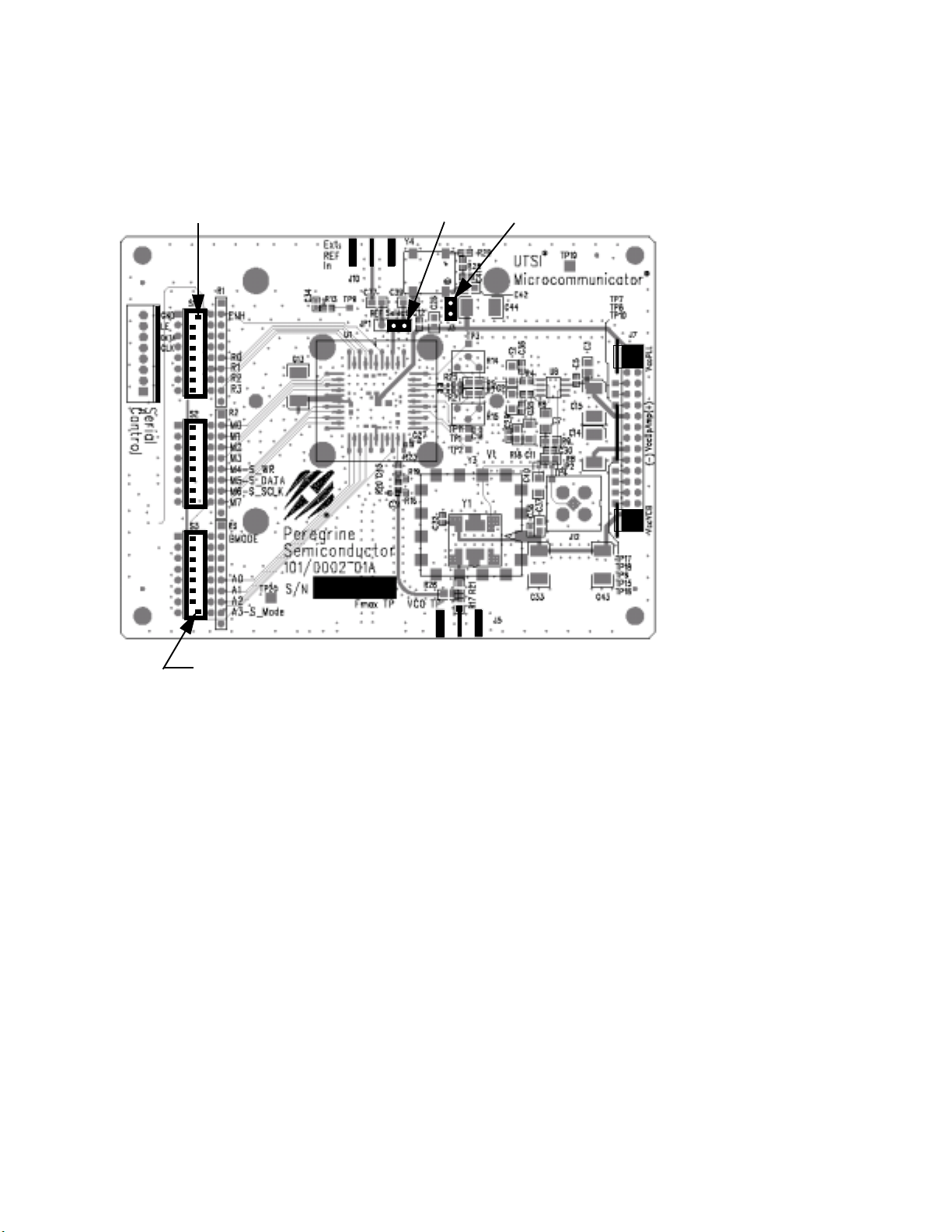
figuration with the default jumper settings shown in Figure 1. Figure 3 shows a
typical set-up for evaluating the PLL using the Evaluation Kit.
Evaluation Kit Set-up
1. Start Microsoft Windows. Insert the Peregrine CD into CDROM drive and
open CD directory. Click Eval Kit Documentation, PE9601-2.2 GHz
Integer-N PLL, and then Evaluation Board Software. Choose the option
of "Save and run the 9601.exe file in your hard disk" or "Run it from CD".
Either way, then run Setup.exe from your hard disk directory and follow the
instruction on the screen. This will install the Evaluation Kit Application
Software. Some computers might not have cb.cfg nor CBERCODE.TXT
file for error log. In this case, you would get an error message during the
initial start up of the software. However, the software will work.
2. There are two sets of jumpers used to configure the Evaluation Board (see
Figure 1). The connector J3 and REF Selector (JP1) select an option to use
the 10 MHz on-board reference or an external reference. Setting the
BMODE Control switch (BMODE switch S3-1) to the "on" position
enables direct mode programming. In the direct mode, the PE9601 can be
programmed using the fifteen on-board switches. Setting the BMODE Con-
trol switch (BMODE switch S3-1) to the "off" position and the A3-S_mode
switch (A3-S_Mode switch S3-8) to the "on" position the serial program-
ming mode is enabled. The Default jumper and switch settings are shown
in Figure 1 which will place the part into serial programming mode. Pere-
grine Semiconductor recommends that the default settings be used initially
to bring up the evaluation board and duplicate the enclosed measured data.
3. Verify a jumper is placed on the connector J3 and REF Selector (JP1) is
positioned to select the on-board reference as shown in Figure 1. The con-
nector J3 supplies power to the on-board TCXO. Do not connect any exter-
nal reference to the connector labeled Ext. REF In (J10) if the on-board
reference is selected. To use an external reference, remove the jumper from
the connector J3 to disable the on-board reference and re-position the
jumper on REF Selector (JP1) as shown in Figure 2. Connect the external
reference to the connector labeled Ext. REF In (J10).

Peregrine Semiconductor Corporation ® 9 Doc. 79/0001~02A
4. Next connect power supply cables to the Evaluation Kit board as shown in
Figure 1. Verify all supplies are turned off prior to connecting to evaluation
board.
a. Connect the 3 V supply to VccPLL [J7, Pins 1(+) & 3(-)].
b. Connect the 5 V supply to VccVCO [J7, Pins 31(+) & 33(-)].
5. Using the application software provided, serial and direct programming can
be evaluated. To enable software control of the evaluation board, ensure all
DIP switches are turned off except for ENH (S1-1) and A3-S_Mode (S3-8)
as shown in figure 1. Direct mode programming can be evaluated manually
without the Application Software enabled. To enable direct mode program-
ming, both the ENH (S1-1) and the Bmode (S3-1) DIP switches should be
turned on. The on-board DIP switches can then be used to manually pro-
gram the PLL. Note that M7 register is not available in the direct mode pro-
gramming. Instructions for programming PLL registers are available in the
datasheet.
6. To perform the evaluation of the PE9601 using the computer’s printer port,
connect the 8-wire interface cable (3-wire serial interface and GND)
between the computer’s printer port and J1 on the Evaluation Board.
7. Connect a spectrum analyzer or similar measurement system to the VCO
Ouput (J5) to access the output of the on-board VCO. Additional GND
posts and test points are available on the Evaluation Board for measurement
flexibility.
8. Apply power to the 5V and 3V supplypins and run the application software.
The Evaluation Kit can now be used to evaluate the PLL. Figure 3 shows a
typical set-up for evaluating the PLL using the Evaluation Kit.

Peregrine Semiconductor Corporation ® 10 Doc. 79/0001~02A
Figure 1. Evaluation Kit Default Jumper & Switch Settings.
S1 Switch 1 On
(Enhanced Mode Off) Ext
REF In JP1 J3
PLL +3V Supply
[J7, Pins 1(+) & 3(-)]
VCO +5V Supply
[J7, Pins 31(+) & 33(-)]
S3 Switch 8 On
(Serial Programming) VCO Out (J5)

Peregrine Semiconductor Corporation ® 11 Doc. 79/0001~02A
Figure 2. Jumper Setting to Disable On-board Reference.
S1
S2
S3
Ext
REF In J3 Removed
JP1 - Jumper on left two pins

Peregrine Semiconductor Corporation ® 12 Doc. 79/0001~02A
Figure 3. Typical Set-up for Evaluation Kit Measurements.
PE3236
TCXO
VCO
Ext REF Inpt
(Do not connect if on-board REF is used)
+3V Supply
J7, Pins 1 & 3
J7, Pins
PLL VDD
VCO VDD +5V Supply
S1
S2
S3
J5 - VCO Output to
Interface to
Computer
Printer Port
8-Wire
Serial
Spectrum Analyzer
31 & 33

Peregrine Semiconductor Corporation ® 13 Doc. 79/0001~02A
Software
Section

Peregrine Semiconductor Corporation ® 14 Doc. 79/0001~02A
Software Setup for Serial Mode Programming
1) When programming the PE9601 in serial mode using the computer printer
port option, the following software programming features are not available:
•Enhancement modes are not available
•Ping-pong mode is not available
•Parallel and Direct interface modes are not available (Note: The direct
mode programming can be performed using the sixteen on-board switches
without using any software)
2) To run the PE9601 programming software using the serial interface mode,
follow steps 1-8 below and Figure 4.
Step 1: Start PE9601 program
Step 2: Under the "IO port type" menu, select "computer printer port"
Step 3: Select "Secondary Register" using the select frequency switch on
the software front panel
Step 4: Set reference frequency to 10 by typing it into the reference fre-
quency box if on-board reference is being used. If an external reference is
used, type in appropriate reference value.
Step 5: Set reference counter (R counter) to 9 by typing it into the R
counter box in the "R M A Select" box in the bottom left corner. Note that
the numbers in the yellow boxes cannot be directly typed in.
Step 6: Verify frequency step = 1.000 MHz.
Step 7: Set Frequency to 1918 by typing it into the secondary frequency
box. Once the frequency values is entered by "Enter" key in the key-
board, the software will automatically send out data to program PLL. You
can click on "Send Data" button to program PLL too.
Step 8: Verify on spectrum analyzer that part locks at 1918 MHz.

Peregrine Semiconductor Corporation ® 15 Doc. 79/0001~02A
Note: Although the "PE9600" symbol appears on the above screen, this software is applica-
ble to the PE9601.
Figure 4: PE3236 Software Control Panel
Table of contents
Other Peregrine Semiconductor Corporation Motherboard manuals