PerfecTron ROC236A User manual

Version 1.1
Revision Date: Nov.11.2019
www.perfectron.com
ROC236A
19” 1U Rack-mount Intel® Ivy Bridge Fanless
Rugged System with Core i7 processors,
9V to 36V DC-in, Extended Temperature. -40
to 70°C
User’s Manual

Safety information
Electrical safety
To prevent electrical shock hazard, disconnect the power cable from the electrical outlet before
relocating the system.
When adding or removing devices to or from the system, ensure that the power cables for the
devices are unplugged before the signal cables are connected. If possible, disconnect all power cables
from the existing system before you add a device.
Before connecting or removing signal cables from the motherboard, ensure that all power cables are
unplugged.
Seek professional assistance before using an adapter or extension cord. These devices could interrupt
the grounding circuit.
Make sure that your power supply is set to the correct voltage in your area.
If you are not sure about the voltage of the electrical outlet you are using, contact your local power
company.
If the power supply is broken, do not try to fix it by yourself. Contact a qualified service technician or
your local distributor.
Operation safety
Before installing the motherboard and adding devices on it, carefully read all the manuals that came
with the package.
Before using the product, make sure all cables are correctly connected and the power cables are not
damaged. If you detect any damage, contact your dealer immediately.
To avoid short circuits, keep paper clips, screws, and staples away from connectors, slots, sockets and
circuitry.
Avoid dust, humidity, and temperature extremes. Do not place the product in any area where it may
become wet.
Place the product on a stable surface.
If you encounter any technical problems with the product, contact your local distributor
Statement
All rights reserved. No part of this publication may be reproduced in any form or by any means,
without prior written permission from the publisher.
All trademarks are the properties of the respective owners.
All product specifications are subject to change without prior notice

Revision History
Revision Date (yyyy/mm/dd) Changes
V1.0 2014/11/18 Initial release
V1.1 2019/11/11 Modify Front I/O
Packing list
□ 19” 1U Rack-mount Intel® HM76 Fanless Rugged System
□ Accessories:
Item
P/N Description Q’ty
1 0P0600000002100L Driver CD 1
2 0F0132500600000L Screw Flat Plating Ni White M4 L:6mm 10
3 0N0600000000010L BRACKET EAR-S 90x43.4x21.3mm 2
4 0F0100500600100L Screw cross circle Plating Ni white w/two washer M3x6 M3 L:6mm 4
If any of the above items is damaged or missing, please contact your local distributor.

Table of Contents
SAFETY INFORMATION ............................................................................................................................................... 1
ELECTRICAL SAFETY ....................................................................................................................................................... 1
OPERATION SAFETY ....................................................................................................................................................... 1
STATEMENT................................................................................................................................................................. 1
REVISION HISTORY .................................................................................................................................................... 2
PACKING LIST ............................................................................................................................................................ 2
TABLE OF CONTENTS ................................................................................................................................................. 3
CHAPTER 1: PRODUCT INTRODUCTION....................................................................................................................... 5
1.1 KEY FEATURES ........................................................................................................................................................ 5
1.2 FRONT PANEL COMPONENTS ..................................................................................................................................... 6
1.3 REAR PANEL COMPONENTS ....................................................................................................................................... 6
1.4 MECHANICAL DIMENSIONS ........................................................................................................................................ 7
CHAPTER 2: JUMPERS AND CONNECTORS ................................................................................................................... 8
2.1 FRONT PANEL CONNECTOR PIN DEFINITIONS.................................................................................................................. 8
2 x USB 2.0 .......................................................................................................................................................... 8
Status Indicators .................................................................................................................................................. 8
2.2 REAR PANEL CONNECTOR PIN DEFINITIONS ................................................................................................................... 8
USB Port: USB2.0 ................................................................................................................................................. 8
LAN port, 2 x RJ45 ............................................................................................................................................... 8
2 x USB 3.0 .......................................................................................................................................................... 9
COM port, RS232................................................................................................................................................. 9
VGA port ............................................................................................................................................................. 9
2.3 INTERNAL CONNECTORS .......................................................................................................................................... 10
Mini PCIe connector .......................................................................................................................................... 10
SATA connector ................................................................................................................................................. 10
CHAPTER 3: INSTALLATION ....................................................................................................................................... 11
3.1 REMOVE THE TOP CASE ........................................................................................................................................... 11
3.2 REPLACE THE TOP CASE ........................................................................................................................................... 11
3.3 2.5" SATA HDD/SSD INSTALLATION ......................................................................................................................... 12
3.4 MEMORY MODULE INSTALLATION .............................................................................................................................. 14
3.5 RACK MOUNT BRACKET INSTALLATION ......................................................................................................................... 15
CHAPTER 4: AMI BIOS UTILITY .................................................................................................................................. 16
4.1 STARTING ............................................................................................................................................................ 16
4.2 NAVIGATION KEYS ................................................................................................................................................. 16
4.3 MAIN ................................................................................................................................................................ 17
4.4 ADVANCED .......................................................................................................................................................... 18
4.4.1 ACPI Settings ............................................................................................................................................. 19
4.4.2 Trusted Computing.................................................................................................................................... 19
4.4.3 CPU Configuration ..................................................................................................................................... 19
4.4.4 SATA Configuration .................................................................................................................................... 20
4.4.5 F81866 Super IO Configuration .................................................................................................................. 20
4.4.6 Serial Port Console Redirection .................................................................................................................. 22
4.4.6.1 Console redirection settings ................................................................................................................... 23
4.4.7 Intel 82579LM Gigabit Network Connection/ Intel 82574L Gigabit Network Connection .............................. 23
4.5 CHIPSET.............................................................................................................................................................. 24
4.5.1 System Agent (SA) Configuration ............................................................................................................... 24
4.6 BOOT ................................................................................................................................................................. 27
4.6.1 CSM Parametes ......................................................................................................................................... 27

4.7 SECURITY ............................................................................................................................................................ 28
4.8 SAVE & EXIT ........................................................................................................................................................ 29

Chapter 1: Product Introduction
1.1 Key Features
System
CPU Type Intel® Ivy Bridge 22nm BGA Type Core™ i7/i5/i3
Core™ i7-3517UE (2C x 1.7 GHz), 4M L2 cache (17W)
Core™ i5-3610ME (2C x 2.7 GHz), 3M L2 cache (35W)
Core™ i3-3217UE (2C x 1.66 GHz), 3M L2 cache (17W)
Chipset Intel® HM76
Memory Type 1 x 204-pin SO-DIMM DDR3 1333/1600 MHz up to 8GB
Expansion Slot 1 x Mini PCIe
Storage Device 1 x 2.5” SATA HDD/SSD
Front I/O
Power Button Yes
Power LED Yes
HDD LED Yes
USB 2 x USB 2.0
Reset Button Yes
Rear I/O
DVI-I 1 (for DVI-D & VGA)
VGA 1
Ethernet 2 x RJ45
COM 1x RS232
USB 2 x USB 3.0,
4 x USB 2.0
DC-in 1 x DC Power Jack 2.5mm
Mechanical & Environment
Power
Requirements
9V to 36V DC-in
Dimension
(W x H x D)
440 x 44.6 x 287.2 mm
(17.32” x 1.73” x 11.30”)
Operating Temp. -20 to 70°C (ambient with air flow)
Storage Temp. -20 to 80°C
Relative Humidity 10% to 90%, non-condensing
Certification CE compliant
*Specifications are subject to change without notice*

1.2 Front Panel Components
1 HDD LED
2 Power LED
3 Power Button
4 2 x USB 2.0
1.3 Rear Panel Components
1 GND
2 Power Input 9V to 24V DC-in
3 2 x USB 2.0
4 2 x USB 2.0
5 LAN port, 2 x RJ45
6 2 x USB 3.0
7 COM port, RS232
8 VGA port
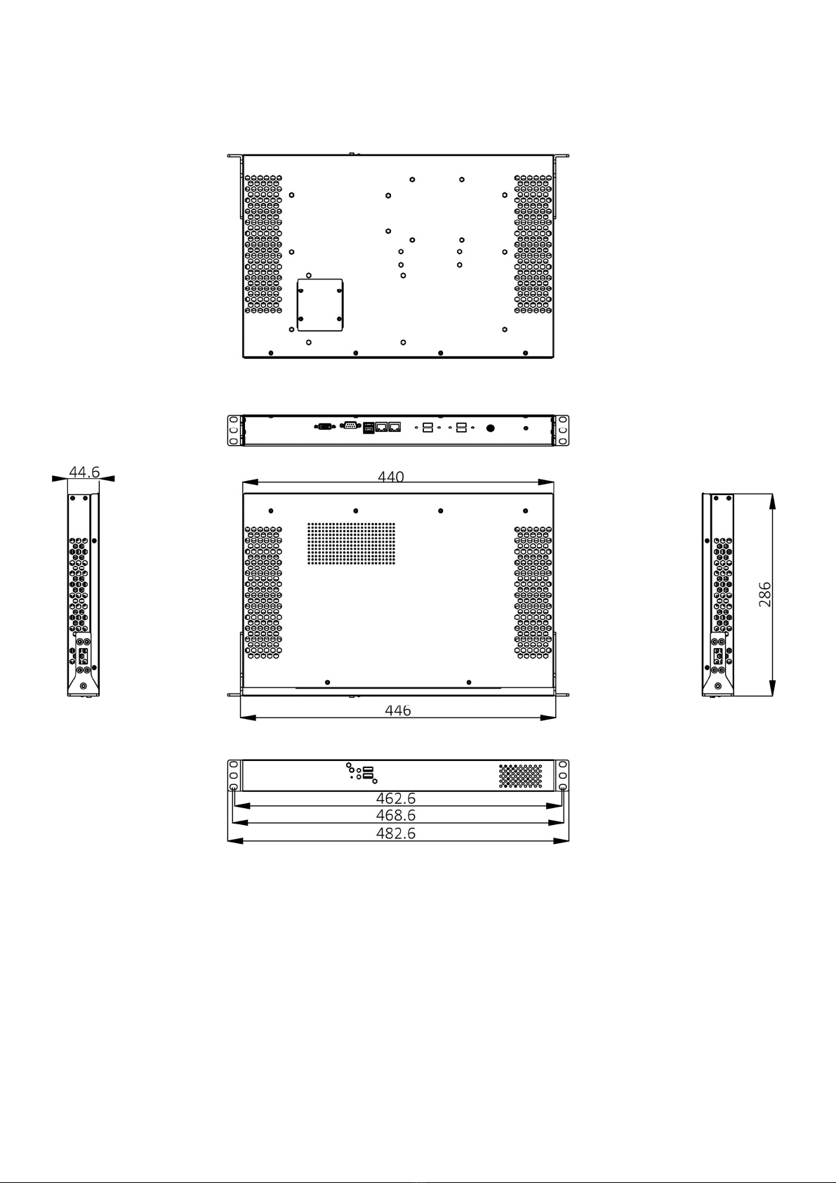
1.4 Mechanical Dimensions

Chapter 2: Jumpers and Connectors
2.1 Front Panel Connector Pin Definitions
2 x USB 2.0
Pin
Definition
Pin
Definition
1 +5V 5 +5V
2 USBD- 6 USBD-
3 USBD+ 7 USBD+
4 GND 8 GND
Status Indicators
Status
LED Color
PWR RED
HDD GREEN
2.2 Rear Panel Connector Pin Definitions
USB Port: USB2.0
Pin
Definition
Pin
Definition
1 +5V 5 +5V
2 USBD- 6 USBD-
3 USBD+ 7 USBD+
4 GND 8 GND
LAN port, 2 x RJ45
Pin Definition
R1 LAN_MDI0P
R2 LAN_MDI0N
R3 LAN_MDI1P
R4 LAN_MDI1N
R7 LAN_MDI2P
R8 LAN_MDI2N
R9 LAN_MDI3P
R10
LAN_MDI3N
SPEED LED ACTIVE LED
Green: 1000Mbps
Orange (blinking): activity
Orange: 100Mbps
No Light: not link
No Light: 10Mbps
Orange (no blinking): link

2 x USB 3.0
Upper USB Lower USB
Pin
Definition Pin
Definition
1 +5VDUAL 1 +5VDUAL
2 D- 2 D-
3 D+ 3 D+
4 GND 4 GND
5 StdA_SSTX- 5 StdA_SSTX-
6 StdA_SSTX+
6 StdA_SSTX+
7 GND_DRIAN
7 GND_DRIAN
8 StdA_SSRX- 8 StdA_SSRX-
9 StdA_SSRX- 9 StdA_SSRX-
COM port, RS232
Pin
Definition
1 DCD#
2 RXD
3 TXD
4 DTR#
5 GND
6 DSR#
7 RTS#
8 CTS#
9 RI#
VGA port
Pin
Definition
Pin
Definition
1 RED 9 +5V
2 GREEN 10
GND
3 BLUE 11
NC
4 NC 12
DDC DATA
5 GND 13
HSYNC
6 GND 14
VSYNC
7 GND 15
DDC LOCK
8 GND
Table of contents
Other PerfecTron Server manuals


