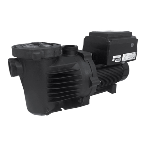
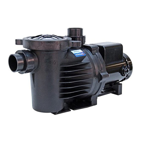
PerformancePro Cascade Series User manual

OWNER’S MANUAL
CASCADE
HIGH RPM PUMPS
PUMP MODEL: ________________________
SERIAL #: ____________________________
DATE PURCHASED: ___________________
5976 SE Alexander St., Ste F, Hillsboro, OR 97123
P (503) 356-5888 F (503) 356-1660 E sales@performancepropumps.com
WWW.PERFORMANCEPROPUMPS.COM
For questions regarding installation, operation or maintenance
call (503) 356-5888
Retain this information for future reference.

Important Safety Instructions
Please read all instructions completely before installing or operating the pump.
Save this manual for future reference regarding installation, operation, maintenance
and troubleshooting of this pump.
Please note the safety warning symbols as noted below:
This warning symbol indicates the potential for personal injury
or damage to the pump! Please be cautious!
WARNING
This symbol indicates a hazard which if not avoided could result
in serious personal injury or death! Please be cautious!
Please carefully read and follow all safety instructions and procedures listed on the pump and in
this manual.
1. This pump and motor unit should be installed by a qualied electrician or service person in accordance
with all applicable state and local codes and ordinances, and in accordance with the National
Electrical Code. Improper installation may create a mechanical or electrical hazard which could
cause damage to property and could result in serious injury or death.
2. In order to avoid serious injury or death, always disconnect power to the motor before servicing
the pump and follow all instructions in this manual.
3. Always use the schematic on the motor for all electrical connections.
4. Never run the pump dry. The Cascade is not self priming and is best suited for ooded suction systems.
The pump housing and entire suction line must be lled with water for proper operation prior to starting
the pump. Running dry will void the warranty and can result in permanent damage to the pump unit.
5. To prevent incorrect motor rotation, install a ball or swing type check valve. Do not use spring check valves.
6. Maintain a minimum ow rate of at least two gallons per minute to avoid damage to the pump unit.
7. Visually inspect the pump and motor a minimum of once per week. If any leakage between the motor
and pump housing is present, replace the mechanical seal. The seal faces wear similar to car tires and
must be replaced periodically. For critical applications, replace the mechanical seal yearly. If pump is
excessively noisy, shut it down and contact support.
8. For 3 phase motors, ensure proper rotation. See section 7 in electrical for details.
GENERAL WARNINGS
WARNING
WARNING
Pressure Hazard!
Do not run your pump
with discharge ports
closed or blocked.
Be sure to release
system pressure before
working on the pump.
Electrical Hazard!
Ground pump
before connecting
to power supply!
Risk of shock, burn
or death if not
handled properly.
Burn Hazard!
Operating motor can be
very hot. Do not touch
motor while running.
Allow to cool 30 minutes
after shut down before
handling. Risk of burn.
SAFETY
2
In freezing environments it is advisable to winterize your pump to prevent damage. Do not allow pump
or system plumbing to freeze, as freezing can cause damage that may lead to equipment failure or
possible injury and will void the warranty.
9.
WARNING
WARNING

3
Understanding priming and pump operation
Your pump is powered by an electric motor that directly aects your water ow rate. When the electric motor
is turned on it utilizes centrifugal force to generate velocity of the water. The water then ows into the
optional strainer pot if installed to lter out debris or if not, will ow directly into the pump housing. Water
continues its ow into the eye of the impeller where the water meets the impeller vanes and converts kinetic
energy into static pressure allowing the pump to maintain pressure and is then forced out of the pumps
discharge port resulting in continuous water ow for your waterscape oasis.
The Cascade High RPM pump is not a self-priming pump which makes it best suited for ooded suction
systems. This means that it is designed to best operate below the water source surface level. Because the
Cascade is not self priming it is recommended to install a rubber apper type swing check valve and a priming
pot to assist in priming unless it is on a gravity fed system. It is important to note that operating above the
water source surface level may negatively aect the pumps overall performance. After lling the pump
housing, intake pipe and priming pot (if present) with water and starting the pump, if there is no water in the
intake pipe between the swing check valve and the water source, a reduced ow may be noticed for a minute.
This is normal and will increase to full performance within a few minutes as long there are no obstructions or
air leaks. If after a few minutes, full ow is not achieved, shut the pump o and check connections.
Never use a spring loaded check valve as it will reduce or stop flow.
What to expect for priming cycle with swing check valve installed.
Essentially, when utilizing a properly installed swing check valve the priming process is less time consuming
and is more ecient. An optional priming pot is also helpful. When installing a swing check valve, be sure your
connections are properly seated and are airtight. The valve should be as low and as close to your source water
as possible to maintain constant pressure. The best installation location for a check valve is underwater when
possible, as this can provide an air tight t even without PVC adhesive. Some swing check valves have true
union connection ttings that oer easier access for cleaning when needed. The pump housing, intake pipe
and strainer pot (if present) are then lled with water until the intake pipe is full. Secure ttings tightly and
turn on your pump. With the swing check valve in place, your pump is fully primed. However, if after running
your pump you observe the water level decreasing continuously, this indicates there is either a blockage
limiting the ow or a union tting connection on the intake pipe is not airtight. Check all
connections for debris, crimping, or cracking and tighten or replace parts as needed.
What to expect for priming cycle without a swing check valve installed.
In installation applications where no swing check valve is installed, it is important to install a priming pot to
facilitate priming. The Cascade series is designed to operate as gravity fed or with a swing check valve and
priming pot installed. Without any of these factors in place, the system will not function properly. If working
with an installed priming pot, the lid should be removed, priming pot lled with water, lid replaced
ensuring all ttings are tight and sealed with PTFE paste or similar sealant. Do Not use PTFE tape.
Be sure all water supply valves are open, then connect the power supply to start the pump. It is important to
note that the resulting water ow may initially be very little for the rst few minutes. If at anytime, no water is
owing into the priming pot, the pump should be shut o, threaded ttings and unions rechecked, water
relled and system restarted. If the problem persists, contact technical support.
Essentially, the Cascade will not have a prime cycle; however, the needs of the system will vary slightly based
on pipe type, diameter, suction lift height, horizontal distance, motor speed and horsepower. A check valve
and a priming pot are excellent tools to aid in the ease of operation of a Cascade pump.
For system specic assessments including suction lift and friction loss guidance and operating questions,
please call 503-356-5888 or email sales@performancepropumps.com.
PUMP OPERATION
The Basics
The Prime
With Valve
No Valve

GENERAL TIPS
Proper installation of your Cascade pump will help ensure years of trouble free service.
1. Position the pump as near to the water and as low as is practical. This will help reduce the time to reach full
ow, avoid cavitation, and maximize your pumps performance.
2. Minimize friction loss by using the appropriate diameter pipe determined by gallons per minute ow,
reducing run length, and minimizing the number of elbows and ttings as much as possible.
3. Maximize your pumps service life by protecting the motor from the elements by ensuring it is well covered
and adequately ventilated. Exposing your pump to excessive heat or moisture will shorten the life of the motor.
4.
Protect the motor against dirt, water, and all foreign matter. If the motor has been ooded,
do not operate it until it has been checked by an authorized motor technician and has been found to be
safe to operate. If the motor is damaged by dirt, moisture, foreign matter or corrosion it is not covered by the
warranty.
5. Mount the motor to a stable base where it will not get submerged. Use caution when installing in a vault.
Be sure proper drainage is in place to prevent ooding. A sturdy pedestal under the pump is benecial
in a vault application to maximize height above the ground. Ensure the vault is properly ventilated.
6. The Cascade series pump ports are 1.5” NPT on both the inlet and discharge ports. The 1.5” NPT ports may be
connected with ttings available from PerformancePro Pumps (MPF-215) or standard 1.5” NPT PVC ttings
available at your local hardware store and should be connected to PVC or ex pipe plumbing.
All plumbing lines should be well supported and properly aligned. This will prevent undue stress to the
housing and ttings. Use a good primer and PVC cement to glue pipe connections.
7. Installations in which the water level is elevated above the pump it is highly recommended to use a
ball or swing type check valve to prevent back ow and possible reverse rotation. A ball valve will
supplement a swing check valve and allow ow adjustments.
8. FILL THE PUMP HOUSING AND ENTIRE SUCTION LINE WITH WATER BEFORE STARTING THE PUMP.
General
Before Installation
Open the pump box when received and inspect for evidence of rough handling or damage to the pump and
verify the product ordered. If damage is found, notify the freight carrier and contact the vendor purchased
from immediately. For order discrepancies, contact the vendor purchased from immediately.
If using smaller than 1.5” pipe, excessive ttings such as elbows, sweeps or reducers, using an excessively
long pipe run, additional strainers or any other water ow restriction device, can increase the time to reach full ow.
Refer to the Pump Operation information on page 3.
9. When determining pump placement, it is important to consider the distance and height from the
water source. To reach full ow without an inline swing type check valve, the pump should be positioned
at or below the water source level unless a priming pot is installed. Positioning is also important to
maintain the pumps ability to maintain prime and minimize cavitation.
Do not use spring loaded check valves!
4
WARNING

INSTALLATION
Installation
1. After thorough inspection, carefully remove the pump from the box.
2. Secure the pump on a solid, at foundation. A covered location is always best and care should
be taken to ensure adequate ventilation. See installation tips for benecial tips.
3. Install a ball or swing type check valve as needed to facilitate pump disconnection, ow control and
servicing.
4. Connect plumbing to the pump by dry t testing rst to ensure proper t and proper pipe
alignment. Be sure all parts are in place before gluing.
5. Once proper t and alignment is established, use proper pipe sealant designed for plastic PVC pipe.
Support plumbing as needed to prevent strain and damage. Do not over tighten ttings.
6. Wiring of this pump should be in accordance with the wiring diagram located on the motor.
Ensure the pump is wired for the correct supply voltage and is supplied by no smaller than 16
gauge wire. The circuit breaker should be 20 amp but no less than 15 amp.
It is recommended that wiring be performed by a licenced electrician.
For 3 phase wiring, see section 7 under Electrical.
7. If your pump will be hardwired, be sure to ground the motor correctly by connecting code
compliant wiring to the green grounding screw located under the wiring plate.
8. When wiring is complete, double check intake and discharge ttings to ensure a snug t.
Note: There may be installations in which plumbing allows for trapped air in the system. If this
happens, priming will be dicult. In this case, loosen the discharge tting slightly to allow
trapped air to bleed o. Once primed tighten the discharge tting.
9. On ooded suction systems where the water source is higher than the pump, the pump will ll
with water once the supply valve is opened. However, on both ooded and non-ooded
systems it is recommended to ll the pump housing and suction line with water.
10. Fill the pump housing and supply lines with water. Turn the motor on by plugging in the unit or
switching on the power supply. Priming should be immediate as Cascade series pumps should be primed
at initial start up. However, with a priming pot attached full prime time may vary in length. See page 3 for
details. Water should continue to ow into the housing as the pump completes the priming process.
The priming process should not take longer than three (3) minutes with continual inow of water. The
pump should never run dry. If at any time water stops owing into the pump housing, shut the pump o
immediately and see Troubleshooting Tips or Pump Operation pages for more information.
Note:
At initial start up, the water level in the pump housing, should drop rapidly and have a small amount of
water entering the pump immediately. If no air leaks or obstructions are present the small amount of
water ow will continue to gradually increase resulting in full ow operating at maximum performance.
5
It is recommended to hire a licensed electrician or experienced serviceperson to install your pump.

6
ELECTRICAL
Electrical
1. Inspect the motors internal wiring to ensure voltage supply is matched between the motor and the
power source. If voltage does not match, it will damage the motor and void the warranty.
Example: If connecting your pump to a 115V circuit, make sure the motor connections match
the 115V wiring diagram listed on your particular motor.
2. Supply voltage must be within +/- 10% of nameplate voltage indicated on the motor. Incorrect
voltage supply may result in re or damaged motor and voids the warranty. If you are not certain,
please consult with a licensed electrician.
3. Use designated supply wire size specied in the chart below. Correct wire size is necessary to
avoid electrical insuciencies, allowing the motor to run cooler, more eciently and eliminating line
voltage loss. It is important to connect your pump to a ground fault circuit interrupter (GFCI) for safety.
4. Wire motor following the connection diagram located on the motor. Note dierences in high and low
voltage arrangements. If a cord has been preinstalled the connection was completed at the factory.
5. Be sure all connections are clean and tight. Ensure the motor is properly grounded. Typically a green
ground terminal is located inside the motor connection box. The ground wire must be properly
connected to an electrical service ground to safely operate.
6. The pump must be connected to an adequately sized circuit. It is recommended to have a dedicated
circuit that will prevent voltage drop from other loads as occurs on shared circuits.
7. When using 3 phase power the motor leads must be energized in the correct sequence to provide
the correct motor rotation. When viewed from the back end (opposite drive end), the motor must
rotate clockwise. Incorrect rotation could destroy the pump and void the warranty.
If sequence of the incoming electrical supply lines is not known, briey connect the power for a
second or two to determine the rotation while looking at the fan through the motor end plate on
the back end (opposite drive end) of the motor. If you are unable to see the fan you will need to
remove the drip cover (solid plate) on the back end of the motor (opposite drive end) in order to see
the motor shaft as this unit type will not have a visable fan. If the rotation is incorrect, exchange any
two of the connected leads and retest.
* Risk of shock! Connect only to a ground fault circuit interrupter (GFCI). Contact an electrician if uncertain.
* Do not bury electrical cord unless installed in certied conduit. Locate the cord safely to minimize accidental damage.
* Replace damaged cords immediately to minimize risk of electric shock.
* Do not use extension cords to supply electricity to the pump.
WARNING
Before wiring any part of the motor be sure the power is disconnected.
It is recommended that wiring be performed be a licensed electrician or professional service person.
If pump has a factory preinstalled cord, wiring has already been set and this step is not needed; unless
voltage change is required in which case the cord will need to be removed and steps followed below.
CIRCUIT DATA WIRING DATA
HP CIRCUIT VOLTS/Hz/PH WIRING SIZE PER AMPERAGE CAPACITY
WIRE GAUGE 25-50 ft 100 ft 150ft 200ft 250ft
1/3 - 1/2 15 Amp
115 or 230/60/1
3/4
20 Amp
115 or 230/60/1
1
20 Amp
115 or 230/60/1
1.5
30 Amp
115 or 230/60/1
2
30 Amp
115 or 230/60/1
16
RECOMMENDED WIRING AND CIRCUIT BREAKER DATA
14
12
10
13 amps 10 amps * * *
15 amps 13 amps 7 amps * *
20 amps 15 amps 10 amps 8 amps 7 amps
20 amps 20 amps 15 amps 10 amps 10 amps
*Not recommended for use at this length. Note: The longer the wiring length the lower the amp conductibility due to voltage drop.
WARNING

Cleaning the basket:
For Cascade systems with an attached strainer pot.
The strainer basket in the priming pot should be inspected and cleaned at least one (1) time
per week, more often if excessive debris is present in the operating environment.
1. Turn o your pump and disconnect from the electrical source by unplugging or turning o
the breaker.
2. If you have a ball valve placed at the return side of your pump, be sure to close the valve to
prevent backow.
3. Remove the lid by holding the tabs and turning counter clockwise. Take care if the lid is too tight.
Slightly bumping the tabs may aid in releasing the grip. Remove the lid and clean out the basket.
It is recommended to clean out the basket using a sprayer on a garden hose and a brush as needed.
Do not hit the basket on any hard surface as this will weaken and damage the basket.
4. Reinstall the basket.
5. Fill priming pot (basket section) with water.
6. Replace the lid securely.
7. Open ball valve (if present).
8. Connect power and start the pump.
If your pump has low incoming water ow at start up, ensure water continues to ow
into the pump. Full ow should be obtained within three (3) minutes with continual
water ow into the pump. If at anytime water stops owing, turn the pump o
immediately. Refer to page 3 for further details.
If the pump runs dry, the volute (main pump housing) may be hot, allow the pump a
minimum of one hour to cool before opening the pipe or pump. The volute housing or
strainer pot (if attached) should be cool to the touch before opening. Danger of burn if
opened when hot.
Seals and Bearings:
Pump seals and bearings experience normal wear and degrade over time. It is recommended to change
pump seals every three (3) to four (4) years for fresh water applications and every year for salt water
applications. The frequency of replacement will be determinate upon environment and water quality. If
leakage is noticed at anytime, check troubleshooting tips and contact us for parts and advice. If the pump
becomes abnormally noisy, this could be a sign that the bearings are failing and need replacement. There
are a few options for repair when an issue occurs.
1. Contact PerformancePro Pumps to obtain a return authorization and ship the pump to us for
repair.
2. Contact PerformancePro Pumps for a list of authorized motor repair centers near you. Note that this
option may not honor any warranty but may provide a good alternative.
3. If you are mechanically minded, the option to order bearings and a seal kit from PerformancePro Pumps
or your local dealer is available for you to perform the repair.
For questions or support contact:
Maintenance
MAINTENANCE
7
WARNING

Pump Disassembly
Tools required: 1. (2) 7/16” wrenches (for 2-3/4” bolts)
2. Large at blade screwdriver
3. Small at blade screwdriver
4. 9/16” open end wrench (for 1” bolts)
Disassembly for repair can be made as follows:
2. Close all necessary valves on inlet and discharge lines and drain the pump by removing both drain
plugs.
3. Loosen and remove the seven (7) 2-3/4” hex bolts that hold the volute and the bracket together.
4. Pull the rear sub-assembly away from the volute. The volute may remain attached to the plumbing.
5.
Hold the motor shaft stationary by removing the cover on the opposite end of the motor.
Insert a screwdriver in the slot or a wrench on the opposite drive end of the motor shaft depending
on the motor design and
unscrew the impeller by turning it counter clockwise as viewed from the
7. Loosen and remove the four (4) 1” hex-bolts that hold the bracket to the motor face. Slide the bracket
away from the motor.
6. To remove the shaft seal, place the bracket face down on a at surface and press out the mechanical
seal from the back side. Never pry it out from the front. Carefully remove the ceramic seal from the
back of the impeller hub by carefully prying up with a small athead screwdriver.
8. Clean the bracket, seal housing and the motor shaft as necessary. Remove slinger if replacing bearings.
If the motor shaft has corrosion build up, use emery cloth to clean it.
8
1. Disconnect the pump from the power source by unplugging or turn o at the circuit breaker.
pump end.
SLINGER
MOTOR
BRACKET
BORE O-RING
MECHANICAL
SEAL
VOLUTE
O-RING
VOLUTE
DRAIN PLUG
WITH ORING
IMPELLER
BRACKET
DRAIN PLUG
WITH ORING
2
-
3/4”
HEX BOLT
1” HEX BOLT
MAINTENANCE

1. To install a new shaft seal, clean or replace the bracket bore o-ring. Moisten bracket bore
o-ring with water prior to installing to prevent rolling.
2. Press the seal into the bore without touching or putting pressure on the delicate carbon face
by pushing on the stainless steel collar. (A large socket or pipe nipple may be used to facilitate
installation.)
3. Clean as necessary the impeller hub and press in the ceramic part (see tip). Make sure that it is
sitting at. The polished white ceramic face must be face out, not the rubber boot! DO NOT
TOUCH THE CARBON SEAL FACE to avoid damage.
Tip: Moistening the rubber boot with water prior to installation aids in proper seating.
4. Install the slinger rubber washer on the motor shaft. Install the bracket to the motor. Install and
tighten the four (4) 1” hex bolts evenly.
5. Screw the impeller clockwise onto the motor shaft while holding the motor shaft stationary until it
makes rm contact.
* Handle the mechanical seal with care to protect the polished and lapped faces of the seal from damage.
* DO NOT RUN THE PUMP DRY. Pump must be lled with water and sealed before it is turned on.
Parts Replacement and Pump Assembly
MAINTENANCE
9
WARNING
6. Make sure the volute o-ring is clean and install the large o-ring in the volute groove.
Tip: Installing the volute o-ring with the volute intake port side down will ease installation of
the bracket o-ring.
7. Assemble the motor sub-assembly to the volute using the seven (7) 2-3/4” hex bolts. Do not tighten
until all seven (7) hex bolts are in place and hand tightened, then tighten all seven (7) bolts uniformly
in an alternating opposing sides pattern. Do not overtighten.
8. Insert both drain plugs with o-rings installed and tighten. If present, install strainer pot and ll
the volute/strainer pot with water.
9. Open all valves on the system and reconnect the power to start. With an attached strainer pot, wait for
the pump to prime while monitoring the water level in the volute/basket area to ensure water is always
present. If the pump has been running with low incoming water ow for more than three (3) minutes,
shut the system o immediately and check ttings for air leaks. Full ow with installed check valve should
be obtained at initial start up. Call PerformancePro Pumps for additional technical assistance.
Tools required: (2) 7/16” wrenches, small & large at blade screwdriver, 9/16” open end wrench (for 1” bolts)
SLINGER
MOTOR
BRACKET
BORE O-RING
MECHANICAL
SEAL
VOLUTE
O-RING
VOLUTE
DRAIN PLUG
WITH ORING
IMPELLER
BRACKET
DRAIN PLUG
WITH ORING
2-
3/4”
HEX BOLT
1” HEX BOLT

Winterization
Winterizing your pump is necessary if freezing temperatures occur in your geographic area for
extended periods of time. If freezing tempuratures are not common but may on occassion drop
below freezing, it is advised to follow winterization procedure to protect your pump.
Freezing tempuratures cause water to expand and may result in damage to the
pump, plumbing, and other connected components resulting in costly repairs.
Full disconnection method:
This method is best for pumps situated outside without protection of a building or vault.
1. Disconnect the pump from the power source by unplugging or turning o at the
circuit breaker.
Note: If hardwired, you may either disconnect the electrical connection (a qualied
electrician should perform this) or you leave the motor connected and disconnect
the pump end. If you choose this option, please follow pump disassembly
instructions and insulate and cover the motor for protection.
2. Close all necessary valves on inlet and discharges lines and drain the pump by
removing both drain plugs. If strainer pot is installed, the lid may be loosened to
facilitate better drainage. Tip: Store drain plugs and union or tting o-rings in a
resealable bag and tape the bag to the pump to prevent loss.
3. Once drained, loosen the intake and discharge port connections.
4. The pump can now be removed. Be sure the pump is fully drained and if strainer pot
is installed remove the lid before being stored. The lid may stay secured if prior to
storage the lid is removed and fully dried. Store with drain plugs removed. Your
pump is now ready for storage in a dry, warm location such as a garage.
**Be sure to drain the water from the plumbing on your system and related
components to prevent damage.
Connected method:
This method is best for pumps situated in a vault, shed or other covered outdoor location
that may be dicult to fully remove.
1. Follow steps 1, 2 and 3 above.
2. Once drained, if strainer pot is installed, remove and dry the lid and place over the
top without latching.
3. Drain all plumbing lines on your system.
4. Insulate the pump and exposed pipes, fully covering to prevent moisture
intrusion and freezing tempurature exposure. Do not directly cover with plastic
sheeting as this can create condensation that can result in damage.
MAINTENANCE
10

Troubleshooting
The following troubleshooting tips support the most common issues. For additional
PROBLEM KNOWN ISSUE TRY THIS
Pump is not priming No water in strainer pot Fill strainer pot with water and close lid.
if installed Ensure plumbing valves are open.
Low water in the strainer pot Check basket to make sure seated correctly and
if installed reinstall lid.
Check lid for cracks and lid oring for at spots or
cracking.
Check intake and discharge union ttings for
cracks or loose connection. Replace or tighten.
Connections must be airtight.
Motor is not turning Circuit breaker has tripped Reset circuit breaker and/or GFCI.
or has no power
Check electric supply to verify power supply is
present. Test a secondary location if needed.
Capacitor failure. This may be tested. Call for
details.
Bearing seized. Rotate motor shaft by hand to test.
If shaft does not freely spin, replace bearings.
Low ow Water ow has slowed or is Clean lter basket of debris if strainer pot installed.
intermittent
Check for impeller clog. See disassembly
instructions or call for details.
Check for leaks in volute housing, lid* and union
connections. (* only if strainer pot installed)
Check for obstructions in plumbing and clear if
found.
Motor overheating Seems overly hot and is Possible incorrect wiring. Have an electrician test.
shutting down or shutting o
and on intermittently Test breaker. Replace if needed.
Increase air ow if restricted.
If pump is located in direct sunlight, try providing a
properly vented shade covering.
Pump is leaking Water leaking between motor Replace mechanical seal and bracket o-ring.
and pump housing
Inspect bolts in volute housing by checking
for loose t of the 7) 2-3/4”bolts. Tighten or replace.
Water leaking at lid* or tting Check lid or ttings for cracks. Replace if needed.
(* only if strainer pot installed) Check lid or tting sealant for cracking or gaps.
Replace if needed.
11
TROUBLESHOOTING

ITEM
DESCRIPTION PART NUMBER
Volute Volute (Front Housing in Noryl)
PNV-15
Volute (Front Housing in Polypropylene)
PPV-15
PVO-10
Impeller Impeller for C1/8-22 (#3)
T: 4.275
CN3/4
Impeller for C1/8-36 (#6) T: 4.09
CN2
Impeller for 1/3 HP, 3450 RPM (#1)
T: 4.80
CN1/3
Impeller for 1/2 HP, 3450 RPM (#2) ODP
T: 4.80
CN1/2
Impeller for 3/4 HP, 3450 RPM and C1/8-26 (#3) ODP T: 4.80
CN3/4
Impeller for 1 HP, 3450 RPM (#4) ODP T: 4.80
CN1
Impeller for 1 1/2 HP, 3450 RPM (#5) ODP T: 4.80
CN1 1/2
Impeller for 2 HP, 3450 RPM and C1/4-44 (#6) ODP
T: 4.80
CN2
Impeller for 3 HP, 3450 RPM and C1/4-49 (#7)
T: 4.80
CN3
Seal 316 Stainless Steel Shaft Seal - Carbon vs. Ceramic with Buna
MPS-513
PTFE Coated S.S. with SIC & Buna
MPS-517
Bracket Bracket (Rear Housing in Noryl)
PNB-10
Bracket (Rear Housing in Polypropylene)
PPB-10
Drain Plug Noryl Drain Plug with O-Ring (1)
PND-20
Polypropylene Drain Plug with O-Ring (1)
PPD-10
Hardware
Washers and Nuts)
Set of Stainless Steel Hardware (includes 2-3/4” Bolts, 1” Bolts,
MPH-20
Volute O-Ring Volute O-Ring
PBO-10
Includes (2) Drain plug o-rings, (1) Bracket &
C-SK1
Bracket bore o-rings, (1) 513 Mechanical seal
Bearing Motor Bearings-03
BEARING-03
Bracket Bore O-Ring Bracket Bore O-Ring
Seal Kit - Standard
Seal Kit - Salt Includes (2) Drain plug o-rings, (1) Bracket &
Bracket bore o-ring, (1) 517 Mechanical seal
C-SK1-S
12
Parts
SLINGER
MOTOR
BRACKET
BORE O-RING
MECHANICAL
SEAL
VOLUTE
O-RING
VOLUTE
DRAIN PLUG
WITH ORING
IMPELLER
BRACKET
DRAIN PLUG
WITH ORING
2
-
3/4”
HEX BOLT
1” HEX BOLT
PARTS

Performance Data
13
PERFORMANCE

Warranty
PerformancePro Pumps
This Cascade series product is warranted tothe Purchaser (defined herein as the original end user) to be free of defects in construction and
workmanship at the time of purchase. Inthe event this product malfunctions within three years (for fresh water use) or one year (for use with salt water
or other suitable fluids) from the date of purchase the sole obligation of PerformancePro Pumps will be to replace or make this product capable of being
operated according tothe original product description without charges for labor or parts to the Purchaser, and are subject to the following conditions:
1. The malfunction is proved attributable to a defect in construction or workmanship, including repairs performed underthis warranty. Malfunction for
any other reason - including but not limited to misuse, abuse, negligence, accident, corrosion or salt build up, incorrect wiring or electrical supply,
tampering with parts, or improper installation - will not be remedied underthis warranty. Problems or damagefrom failure to comply with instructions in
the owner’s manual, improper plumbing and positioning, flooding, incompatibility with fluid chemisty and running the unit dry are not covered under
this warranty.
2. PerformancePro Pumps must perform all warranty repairs. Purchaser must retain the purchase receipt and present it with this certificate as proof of
ownership and entitlement to warranty repairs. The cost of unauthorized repairs will not be reimbursed to Purchaser by PerformancePro Pumps, and
are not the responsibility of PerformancePro Pumps. If repairs by Purchaser or a third party damage the product, such damage is not remediable under
this warranty.
3. Purchaser shall bear all shipping, packing, and insurance costs and all othercosts, excluding labor and parts necessary to effectuate repairs under
this warranty. Purchaser will pay for return freight.
4. For applications that involve fluids otherthan water, the Purchaser shall retain and presentto PerformancePro Pumps evidence of purchaser’s
compatibility tests under actual operating conditions. Any problems caused by a chemical incompatibility of the fluid with the pump materials, are
expressly notcovered by this warranty.
5. Periodic check-ups and/or maintenance are not covered by this warranty.
6. For all sales in the State of Oregon this is the sole and exclusive manufacturer’s warranty. There are no warranties which
extend beyond the warranty set forth herein, and in accord with Oregon Revised Statutes ORS 72.3160 any and all implied
warranties, including any warranties of merchantability and fitness for particular purpose, are disclaimed and excluded. Some
States do not allow disclaimers/exclusions of, or limitations on how long an implied warranty lasts, so in such States, and
except as is otherwise provided by applicable law of said States, no action on a warranty implied at law shall be commenced
more than one year following the date of purchase. No action shall be brought for breach of any express warranty subsequent
to the expiration of the express written warranty.
7. Incidental and consequential damages (specifically including, but not limited to, damages for loss of profits or damages
relating to down time of personnel, equipment, or facilities) caused by malfunction, defect, or otherwise, whether alleged to
be the result of breach of any express or implied warranty, or the negligence, willful misconduct or other act of
PerformancePro Pumps are not the responsibility of PerformancePro Pumps, and to the extent permitted by law, are hereby
excluded, including, but not limited to property damage, and to the extent not prohibited by applicable law, personal injury or
death and Purchaser hereby agrees to expressly waive any claim for all such damages. If a final determination is made in a
court of competent jurisdiction that any one or more of the damages which are disclaimed, excluded and/or waived under this
paragraph are not allowed under public policy or applicable law, then the disclaimer, exclusion and waiver of all of the other
damages not prohibited by public policy or applicable law shall continue to apply.
8. This warranty does not apply to any malfunction arising out of any application of this product otherthan in a use compatible with the manufacturer’s
product description, unless such application is, upon request, specifically approved in writing by PerformancePro Pumps.
9. The provisions of this warranty are severable and if any provision shall be deemed invalid, the remaining provisions shall remain in full force and
effect.
10. This limited warranty extends only to the original Purchaser (end user) and does not extend to transferee or purchaser from the original Purchaser.
Any purported assignment withoutthe consent of PerformancePro Pumps shall be null and void.
11. No warranty whatsoever of chemical compatibility or application suitability is given. It is the sole responsibility of the Purchaser to determine if the
merchandise purchased is suitable for Purchaser’s specific application. PerformancePro Pumps strongly advises thatthe customer perform any and all
tests necessary to determine material compatibility and product suitability for customer’s specific conditions and needs.
12. This contract shall be governed by and in accordance with the laws of the State of Oregon. Purchaser agrees that proper jurisdiction and venue for
anyclaim brought hereunder is in Washington County, Oregon.
13. This limited warranty is incorporated by reference into the contract of purchase for the products supplied by PerformancePro Pumps to Purchaser
under said contract.
14
WARRANTY
Cascade Series
Limited Warranty

PROTECT YOUR INVESTMENT!
Exposure to the elements can result in corrosion
and reduced service life of your pump.
Protect your pump motor from the elements today!
* Excellent weather protection * Noise abatement * Easy to assemble
* Sturdy construction * Customizable precut knockout sections
* Fits Artesian, Artesian 2, ArtesianPro and Cascade series
MPC-10
14”
15”
15”
Part #:
Table of contents
Other PerformancePro Water Pump manuals
Popular Water Pump manuals by other brands

Ecolab
Ecolab 00002 operating instructions

ProMinent
ProMinent mikro g/5a instruction manual

ANDO Technik
ANDO Technik Dosatron D 25 F owner's manual

Edwards
Edwards iXH100 instruction manual

Pacific hydrostar
Pacific hydrostar 69746 Owner's manual & safety instructions

salmson
salmson SUBSON 10 Installation and starting instructions