PerkinElmer 5184 User manual

Model 5184
Ultra Low-Noise
Voltage Preamplifier
Instruction Manual
222516-A-MNL-D
Copyright © 2000 PERKINELMER CORPORATION

FCC Notice
This equipment generates, uses, and can radiate radio-frequency energy and, if not installed and
used in accordance with this manual, may cause interference to radio communications. As
temporarily permitted by regulation, operation of this equipment in a residential area is likely to
cause interference, in which case the user at his own facility will be required to take whatever
measures may be required to correct the interference.
Company Names
PerkinElmer Instruments is part of Perkin Elmer, Inc., and includes the businesses formerly trading
as EG&G Princeton Applied Research, EG&G Instruments and EG&G Signal Recovery.
Declaration of Conformity
This product conforms to EC Directives 89/336/EEC Electromagnetic Compatibility Directive,
amended by 92/31/EEC and 93/68/EEC, and Low Voltage Directive 73/23/EEC amended by
93/68/EEC.
This product has been designed in conformance with the following IEC/EN standards:
EMC: BS EN55011 (1991) Group 1, Class A (CSPIR 11:1990)
BS EN50082-1 (1992):
IEC 801-2:1991
IEC 801-3:1994
IEC 801-4:1988
Safety: BS EN61010-1: 1993 (IEC 1010-1:1990+A1:1992)
Trademarks
is a trademark of PerkinElmer, Inc.

Table of Contents Table of Contents
i
Chapter One, Description
1.1 Description ................................................................................................................................................. 1-1
1.2 Options....................................................................................................................................................... 1-2
Chapter Two, Initial Checks
2.1 Introduction ................................................................................................................................................ 2-1
2.2 Equipment Needed ...................................................................................................................................... 2-1
2.3 Procedure.................................................................................................................................................... 2-1
Chapter Three, Operating Instructions
3.1 Introduction ................................................................................................................................................ 3-1
3.1.01 Power Switch..................................................................................................................................... 3-1
3.1.02 Input.................................................................................................................................................. 3-1
3.1.03 Output ............................................................................................................................................... 3-1
3.2 Battery Operation........................................................................................................................................ 3-2
3.3 External Supply Operation.......................................................................................................................... 3-2
Appendix A, Specifications
Appendix B, External Power Supply
Warranty................................................................................................................................. End of Manual

TABLE OF CONTENTS
ii

Description Chapter 1
1-1
1.1 Description
The model 5184 is a medium-impedance (5 MΩ), AC-coupled, voltage preamplifier
which features an ultra low-noise FET input stage (800 pV/√Hz at 1 kHz). It has a
frequency range of 0.5 Hz to 1 MHz and a fixed gain of 60 dB (×1000). The 5184 is
ideal for use with medium impedance cryogenic sources and IR detectors such as
HgCdTe, InSb and InAs.
The model 5184 incorporates a special input stage which can be floated to give the
ground loop immunity normally associated with differential inputs, without the usual
accompanying noise penalty of the input devices required in differential circuits.
The model 5184 can be powered from its own internally housed (alkaline) batteries, an
external low voltage supply (±15 V or ±18 V DC) or from a line power supply via the
model PS0108 (optional extra). It can also be powered from most PerkinElmer
Instruments lock-in amplifiers. Connection of external power to the instrument is by a
5-way DIN connector on the rear panel.
Figure 1-1, Model 5184 Front Panel
Figure 1-2, Model 5184 Rear Panel

Chapter 1, DESCRIPTION
1-2
1.2 Options
The model 5184 is supplied complete with four 9 V alkaline batteries. The following
optional extras are available.
Model PS0108 Remote Line Power Supply for the model 5184. See Appendix B
for details of this unit.
Model PS0109 Pack of 20 alkaline batteries for the model 5184
Model C0218 Power cable. This cable allows the user to power the model
5184 from any one of the following PerkinElmer Instruments
Lock-in Amplifiers:
Model 5102, 5104, 5109, 5110, 5205, 5206, 5207, 5208, 5209,
5210, 5302, 7220, 7225, 7260, 7265 or 7280.
Model K0304 Rack mounting kit. This allows 1 or 2 model 5184 preamplifiers
to be mounted in a standard 19" rack.

Initial Checks Chapter 2
2-1
2.1 Introduction
The following procedure is provided to facilitate initial performance checking of the
Model 5183. In general, the procedure should be performed after inspecting the
instrument for shipping damage, but before using it experimentally. If any damage is
noted, PerkinElmer Instruments should be notified immediately and a claim filed with
the carrier. The shipping container should be saved for inspection by the carrier.
Should any difficulty be encountered in carrying out these checks, contact the factory
or one of its representatives.
2.2 Equipment Needed
1) General purpose laboratory oscilloscope.
2) Signal generator capable of providing a 10 mV pk-pk sine wave at 1 kHz.
2.3 Procedure
1) Set the front-panel POWER switch to the down (BATTERY) position. Then
press the adjacent POWER TEST button. The associated indicator should light,
indicating that the internal batteries are installed and functioning properly. If the
POWER TEST indicator does not light, refer to Section 3.2 for a discussion of
the 5184’s battery requirements.
Note: Those users who have purchased the PerkinElmer Instruments external
power supply option can use the external supply to perform the initial checks, in
which case step 1 is replaced by the following operations.
a) Make sure that the voltage selector switch on the external power supply is in
the position indicating the line voltage to be used (110 V AC or 240 V AC).
b) Plug the line cord into the external power supply and the external power
supply into the instrument power socket.
c) Set the POWER switch to the up (EXTERNAL) position. Then press the
adjacent POWER TEST button. The associated indicator should light,
indicating that the external supply is functioning properly.
2) Set the 5184 input GROUND / ISOLATE switch to the down (GROUND)
position.
3) Connect the oscilloscope to the OUTPUT BNC connector.
4) Allow approximately 1 minute for the model 5184 circuitry to stabilize

Chapter 2, INITIAL CHECKS
2-2
5) Set the signal generator to 1 kHz, 10 mV pk-pk and connect it’s output to the
INPUT BNC connector. Use the oscilloscope to monitor the signal generator
amplitude settings so as to obtain consistency between input settings and output
readings.
6) Monitor the 5184 output; the output level should be 10 V pk-pk.
7) Set the 5184 input GROUND / ISOLATE switch to the up (ISOLATE)
position.
8) The output level should still be 10 V pk-pk.
9) Return the POWER switch to the center (OFF) position.
This completes the initial checks. If the instrument performed as indicated, one can be
reasonably sure that it has arrived in good working order and is functioning properly.

Operating Instructions Chapter 3
3-1
3.1 Introduction
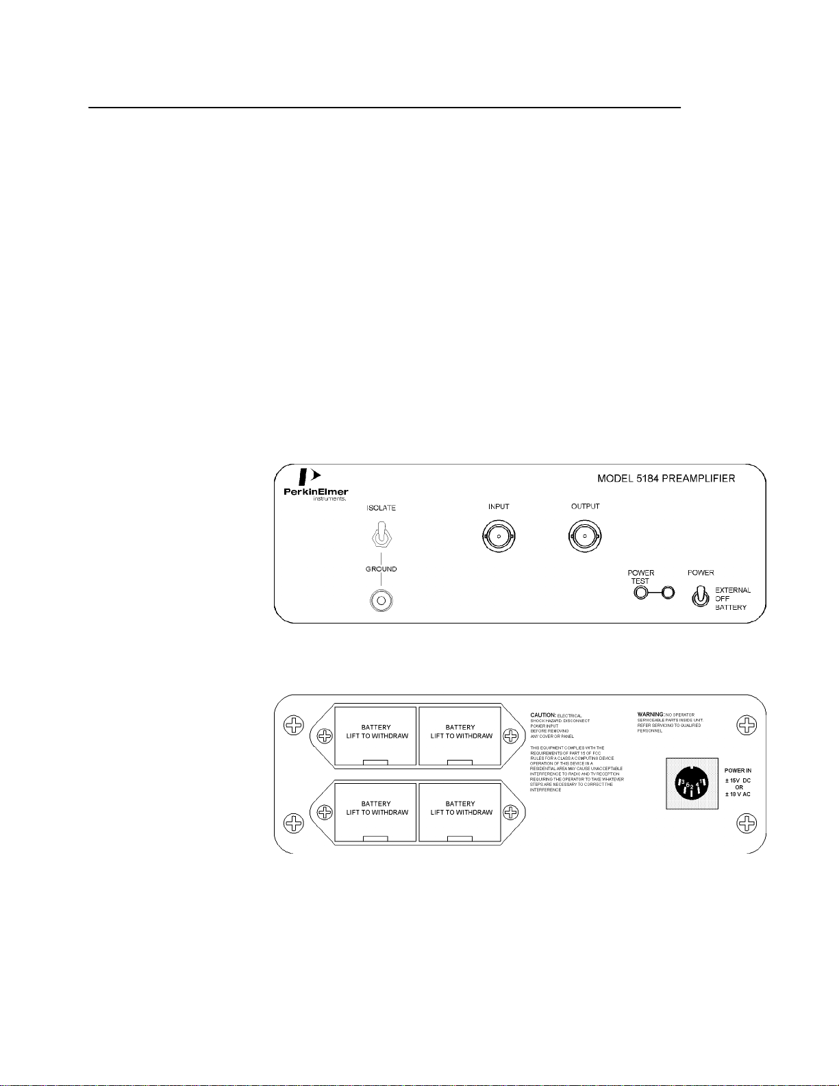
The Model 5184 Preamplifier can be powered from an external power source or from
internal alkaline cells as selected from a front-panel switch. In operation, the voltage to
be measured is connected to the AC-coupled INPUT BNC connector. The
preamplifier amplifies the signal voltage by a fixed 60 dB (1000 times) which is then
output from the OUTPUT BNC connector.
3.1.01 Power Switch
The three position POWER switch allows EXTERNAL, OFF, or BATTERY to be
selected. To operate the 5184 from an external power source, set the switch to the up
position. To operate the 5184 from internal batteries, set the switch to the down
position. In the center position, the 5184 is unpowered. The status of the selected
power source can be ascertained by pressing the POWER TEST button; the adjacent
LED will light if the power source voltage, whether of the external power source or the
5184 internal batteries, is above the minimum required value for reliable operation.
3.1.02 Input
The 5184 input circuit is of an asymmetrical differential configuration. When the
GROUND / ISOLATE switch is set to the down (GROUND) position, the screen of
the BNC input socket is grounded and the input may be used in the conventional
single-ended mode. When the GROUND / ISOLATE switch is set to the up
(ISOLATE) position, the input stage is floated and the input may be used in the
“pseudo-differential”mode. This gives the ground loop immunity normally associated
with differential inputs without the accompanying noise penalty associated with
differential input stages. In “pseudo-differential”mode the signal voltages should be
connected to the BNC INPUT socket and the signal ground to the GROUND terminal
on the front panel. The maximum common mode input voltage is 300 mV peak to peak
and the maximum voltage difference between the shell of the BNC signal input
connector and the front panel ground terminal is ±600 mV.
3.1.03 Output
The 5184 output can generate greater than 10 V peak to peak signals into loads greater
than 100 kΩ. The 450 ohm output impedance provides a convenient 10:1 output
attenuator if the amplifier is loaded with 50 ohms, which can be useful if the 5184 is
required to drive coax cable greater than one meter in length at signal frequencies
approaching 1 MHz.

Chapter 3, OPERATING INSTRUCTIONS
3-2
3.2 Battery Operation
In battery powered operation, the 5184 requires four 9 V alkaline cells (type NEDA
1604, PP3 or equivalent). Each battery fits into its own removable tray accessible
from the rear panel. When they are exhausted, all four batteries should be replaced
together. Care should be taken when exchanging the batteries to observe the correct
polarity which is marked on the inside of the battery trays and the top of the batteries.
The batteries will provide up to eight hours operation at 1 V rms. output level.
Nickel-cadmium rechargeable batteries can be used if preferred, but there will be a
penalty of a reduction in the operating time obtained. In addition it will be necessary to
recharge these batteries in an external charger.
Figure 3-1, Battery Type
3.3 External Supply Operation
External power can be provided by a stand-alone external power supply (see
Appendix B) providing ±18 V DC, or the Preamplifier Power Output of most
PerkinElmer Instruments lock-in amplifiers which provide ±15 V DC. Connection is
by a DIN 5-way socket on the rear panel of the 5184.
Figure 3-2, External Power Input Connector Pinout

Specifications Appendix A
A-1
General
AC coupled voltage amplifier with fixed x1000 (60dB) voltage gain and a maximum
frequency response extending from 0.5 Hz to 1 MHz. Pseudo-differential input and
single-ended output via BNC connectors.
Battery powered from internal alkaline batteries or external DC power supplies.
Input
Modes Asymmetrical differential. Front panel ground
terminal provided.
Coupling AC
Impedance 5 MΩ//50 pF
Frequency Response 0.5 Hz - 1 MHz
C.M.R.R. > 80 dB (100 Hz to 1 kHz)
Max differential input voltage 10 mV pk-pk
Max common-mode input voltage 300 mV pk-pk
Max signal low potential w.r.t. ground terminal
±600 mV
Max input without damage ±15 V DC or 10 V rms. AC @ 50 Hz
Noise See Figure A-1 ; typ 800 pV/√Hz @ 1 kHz
Figure A-1, Model 5184 Noise Figure Contours (Typical)
Gain x1000 (60 dB) fixed
Gain Accuracy ±1%
Gain Stability ±800 ppm/°C
Output

Appendix A, SPECIFICATIONS
A-2
Impedance 450 Ω
Max voltage swing >10 V pk-pk
Slew rate > 22 V/µs
Polarity Non-inverting
Distortion < 0.1% T.H.D.
Power
Internal Four 9 V alkaline batteries provide
approximately 8 hours of use
External
a) ±15 V or ±18 V DC @
40 mA
b) 110 V AC or 240 V AC via optional
external model PS0108 power supply
Dimensions
(excluding connectors) 8.25" wide ×11" deep ×3.5" high
(210 mm wide ×279 mm deep ×89 mm high)
Weight 5.3 lbs. (2.4 kg) excluding optional power supply

Power Supply Unit
(Model PS0108) Appendix B
B-1
Figure B-1, Model PS0108 External Power Supply
Fuse Rating
115 V operation 200 mA
230 V operation 100 mA
Fuse Type 5 mm ×20 mm, 250 V, Slow Blow

Appendix B, POWER SUPPLY UNIT (MODEL PS0108)
B-2

WARRANTY
PerkinElmer Instruments Corporation warrants each instrument of its own manufacture to be free of defects in material and
workmanship for a period of ONE year from the date of delivery to the original purchaser. Obligations under this Warranty
shall be limited to replacing, repairing or giving credit for the purchase, at our option, of any instruments returned,
shipment prepaid, to our Service Department for that purpose, provided prior authorization for such return has been given
by an authorized representative of PerkinElmer Instruments Corporation.
This Warranty shall not apply to any instrument, which our inspection shall disclose to our satisfaction, to have become
defective or unusable due to abuse, mishandling, misuse, accident, alteration, negligence, improper installation, or other
causes beyond our control. This Warranty shall not apply to any instrument or component not manufactured by PerkinElmer
Instruments Corporation. When products manufactured by others are included in PerkinElmer Instruments Corporation
equipment, the original manufacturers Warranty is extended to PerkinElmer Instruments customers.
PerkinElmer Instruments Corporation reserves the right to make changes in design at any time without incurring any
obligation to install same on units previously purchased.
THERE ARE NO WARRANTIES WHICH EXTEND BEYOND THE DESCRIPTION ON THE FACE HEREOF. THIS WARRANTY IS
IN LIEU OF, AND EXCLUDES ANY AND ALL OTHER WARRANTIES OR REPRESENTATIONS, EXPRESSED, IMPLIED OR
STATUTORY, INCLUDING MERCHANTABILITY AND FITNESS FOR A PARTICULAR PURPOSE, AS WELL AS ANY AND ALL
OTHER OBLIGATIONS OR LIABILITIES OF PERKINELMER INSTRUMENTS CORPORATION, INCLUDING, BUT NOT
LIMITED TO, SPECIAL OR CONSEQUENTIAL DAMAGES. NO PERSON, FIRM OR CORPORATION IS AUTHORIZED TO
ASSUME FOR PERKINELMER INSTRUMENTS CORPORATION ANY ADDITIONAL OBLIGATION OR LIABILITY NOT
EXPRESSLY PROVIDED FOR HEREIN EXCEPT IN WRITING DULY EXECUTED BY AN OFFICER OF PERKINELMER
INSTRUMENTS CORPORATION.
SHOULD YOUR EQUIPMENT REQUIRE SERVICE
A. Contact your local PerkinElmer Instruments (Signal Recovery) office, agent, representative or distributor to discuss the
problem. In many cases it may be possible to expedite servicing by localizing the problem to a particular unit or cable.
B. We will need the following information, a copy of which should also be attached to any equipment which is returned
for service.
1. Model number and serial number of instrument
2. Your name (instrument user)
3. Your address
4. Address to which the instrument should be returned
5. Your telephone number and extension
6. Symptoms (in detail, including control settings)
7. Your purchase order number for repair charges (does
not apply to repairs in warranty)
8. Shipping instructions (if you wish to authorize
shipment by any method other than normal surface
transportation)
C. If you experience any difficulties in obtaining service please contact:
PerkinElmer Instruments (Signal Recovery)
801 South Illinois Avenue Phone: +1 423 483 2121
Oak Ridge Fax: +1 423 483 0396
USA
or PerkinElmer Instruments (Signal Recovery)
Sorbus House Phone: +44 (0)118 977 3003
Mulberry Business Park Fax: +44 (0)118 977 3493
United Kingdom
Table of contents
Other PerkinElmer Amplifier manuals