Perytech PLA-1664 User manual
Peregrine Technology CO.,LTD.
Logic Analyzer
User Manual

沛瑞科技股份有限公司 TEL:886-2-2984-0000
www.perytech.com Peregrine Technology CO., LTD. FAX:886-2-2983-9999
1
Contents
Safe Use Specifications...........................................................................................................................3
1. System Requirement.......................................................................................................................4
2. Package Content............................................................................................................................... 5
3. Exterior Appearance of the Logic Analyzer...........................................................................6
4. Software Installation .......................................................................................................................7
5. Logic Analyzer Software Operating Instructions ............................................................... 8
5.1. Quick start .......................................................................................................................................8
5.2. Setting the trigger condition ............................................................................................... 10
5.3. Setting the size of the memory and the sampling rate............................................ 11
5.4. Setting trigger position .......................................................................................................... 12
5.5. Screen scaling ............................................................................................................................. 13
5.6. Move screen ................................................................................................................................ 14
5.7. Move the previous/next waveform edge....................................................................... 15
5.8. Hot key list.................................................................................................................................... 16
5.9. Channel editing (add, delete, rename) ............................................................................ 17
5.10. Cursor function...................................................................................................................... 18
5.11. Bus decoding function ....................................................................................................... 19
5.12. Bus packet list function ...................................................................................................... 23
5.13. Search bus data ..................................................................................................................... 24
5.14. Bus displayed as analog type .......................................................................................... 25
5.15. File function............................................................................................................................. 26
5.16. Synchronizing waveforms from two files................................................................... 27
5.17. Printing function ................................................................................................................... 29
5.18. Data export function........................................................................................................... 30
5.19. External clock input.............................................................................................................. 33
5.20. Trigger width........................................................................................................................... 35
5.21. Set trigger voltage................................................................................................................ 37
5.22. Delay trigger ........................................................................................................................... 38
5.23. Data filter.................................................................................................................................. 39
5.24. Noise filter................................................................................................................................ 41
5.25. Data inverse function.......................................................................................................... 42

沛瑞科技股份有限公司 TEL:886-2-2984-0000
www.perytech.com Peregrine Technology CO., LTD. FAX:886-2-2983-9999
2
5.26. Packet trigger function....................................................................................................... 44
5.27. Frequency counter function............................................................................................. 45
5.28. Compression function ........................................................................................................ 46
6. Specification .................................................................................................................................... 48

沛瑞科技股份有限公司 TEL:886-2-2984-0000
www.perytech.com Peregrine Technology CO., LTD. FAX:886-2-2983-9999
3
Safe Use Specifications
Thank you for choosing Perytech instruments. Before you start using our instrument,
please read the safe use specifications and understand the accurate method of use.
When using the instrument(s), please follow the safety rules to ensure the product is
functioning normally.
Please do not remove the outer casing: removing the outer casing can cause
electrocution and can damage the internal components.
Please connect the grounding end correctly: please do not connect the grounding
end to the power source to prevent damage to the logic analyzer and computer.
Please do not use oscilloscope in high temperatures and high humidity environments
or near flammable materials. This is to prevent damage to the logic analyzer.
If the instrument will not be used for a long time, please remove the USB cable to
conserve power.


沛瑞科技股份有限公司 TEL:886-2-2984-0000
www.perytech.com Peregrine Technology CO., LTD. FAX:886-2-2983-9999
5
2. Package Content
Product Name
Quantity
Logic analyzer
1
USB cable
1
8P colored test wire
2 or 4*
2P black test wire
1
1P white test wire
1
Clips
18 or 36*
Software CD
1
*The 16 channel model has two sets of 8P colored test wire and 18 clips. The 32
channel model has four sets of 8P colored test wire and 36 clips.
沛瑞科技股份有限公司 TEL:886-2-2984-0000
www.perytech.com Peregrine Technology CO., LTD. FAX:886-2-2983-9999
6
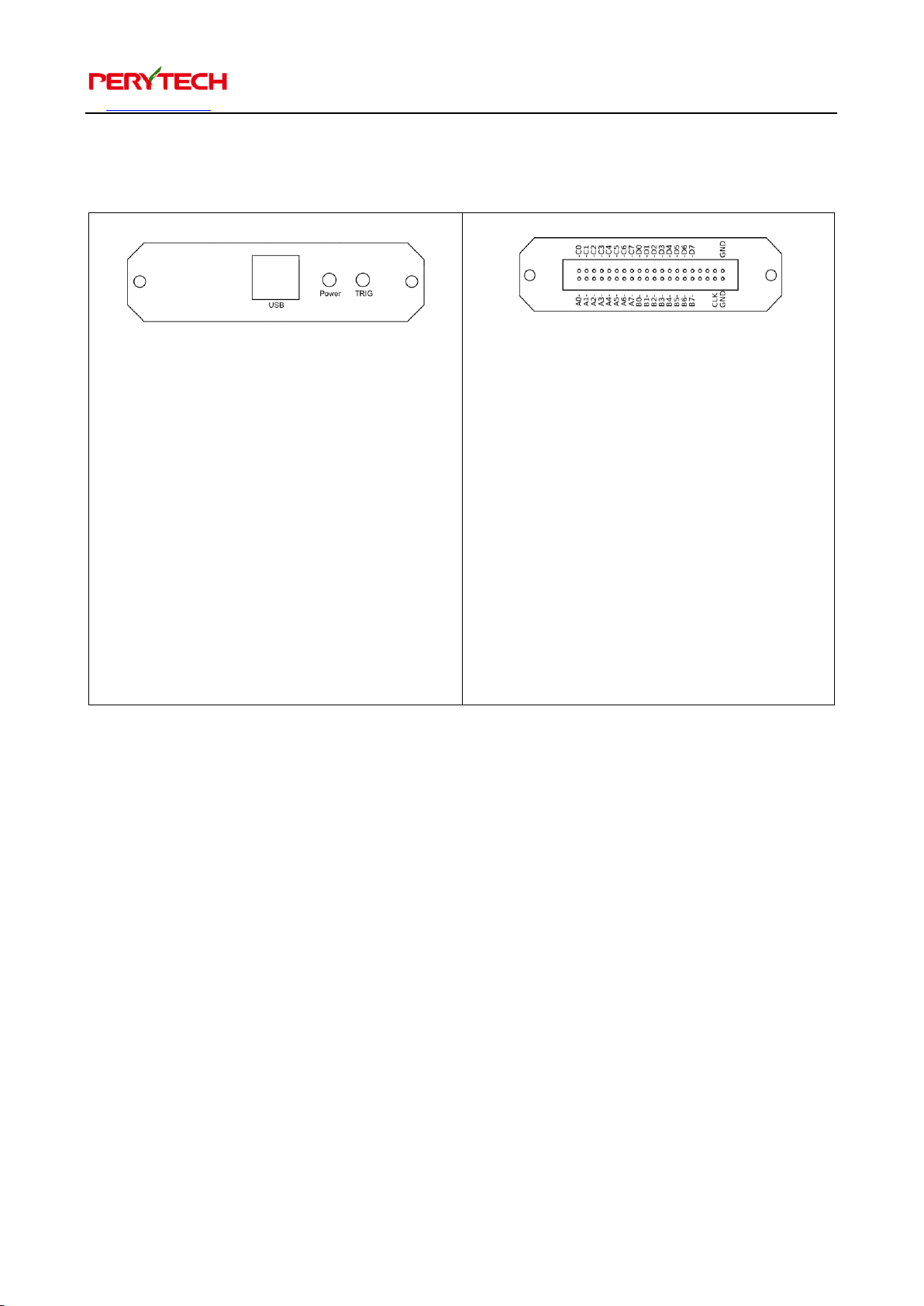
3. Exterior Appearance of the Logic Analyzer
⚫USB Port: interface between the logic
analyzer and computer
communication.
⚫Power LED: when power supply is
normal this will shine red light.
⚫TRIG LED: when the signal triggers
this will shine green light.
⚫A0 - A7: signal input Port A
⚫B0 - B7: signal input Port B
⚫C0 –C7: signal input Port C
⚫D0 –D7: signal input Port D
⚫GND: ground
⚫CLK: exterior clock input.

沛瑞科技股份有限公司 TEL:886-2-2984-0000
www.perytech.com Peregrine Technology CO., LTD. FAX:886-2-2983-9999
7
4. Software Installation
The attached CD contains the LA installation software. The file name is
“LA_Install_V1.xx.exe” and the xx is the edition number. You can also download the
installation software from the Perytech website. Implement to install the software.
Software installation is very simple. Just press “Next.” The driver will also be installed
together. After installation is complete, an “LA” shortcut will appear on the desktop
and in the start function, as shown below.

沛瑞科技股份有限公司 TEL:886-2-2984-0000
www.perytech.com Peregrine Technology CO., LTD. FAX:886-2-2983-9999
8
5. Logic Analyzer Software Operating Instructions
5.1. Quick start
Click the LA shortcut on the desktop to activate the LA software. The following figure
is the software screen for the 32 channel model logic analyzer. If the instrument is a 16
channel model then the channel number would be 16. Except for the different
number of channels, the operating method for the 16 and 32 channel logic analyzer is
the same.
沛瑞科技股份有限公司 TEL:886-2-2984-0000
www.perytech.com Peregrine Technology CO., LTD. FAX:886-2-2983-9999
9
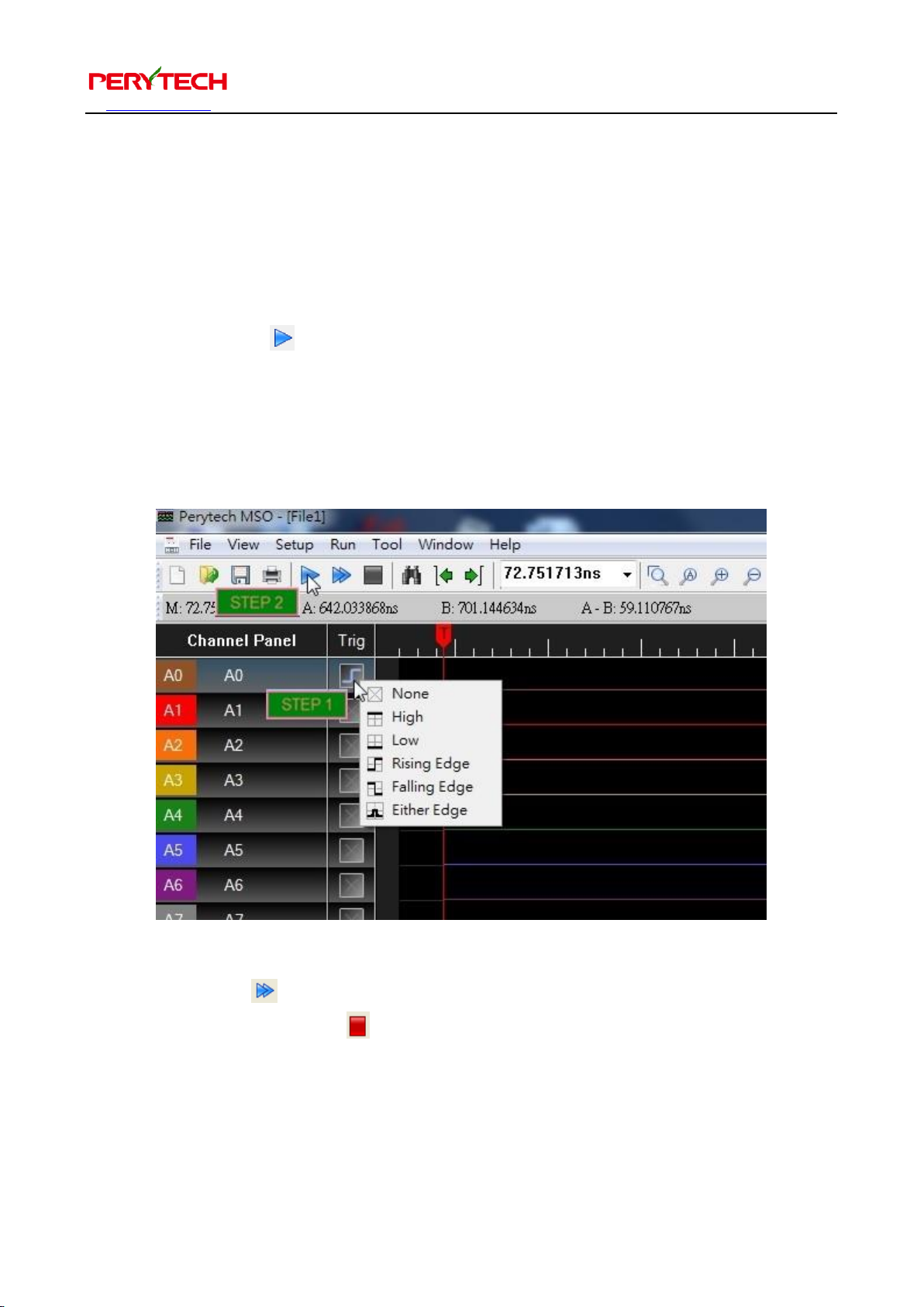
Basic operation of the logic analyzer requires only two steps:
1. Setting trigger conditions: click the Trig box (where the mouse cursor is in the
below figure) to set the trigger condition. Here we set the trigger condition as
Channel A0 rising edge.
2. Press the “Run” button.
After pressing the “Run” button, the logic analyzer will start to detect trigger signals.
When the trigger signal appears, the analyzer will transmit the data from the logic
analyzer back to the PC. The PC screen will show the waveform.
The “Repeat Run” next to the Run button is used to repeat the Run. If you wish to
stop, press the “Stop” button on the side at any time.
This manual suits for next models
4
Table of contents
Popular Measuring Instrument manuals by other brands

Powerfix Profi
Powerfix Profi 278296 Operation and safety notes

Test Equipment Depot
Test Equipment Depot GVT-427B user manual

Fieldpiece
Fieldpiece ACH Operator's manual

FLYSURFER
FLYSURFER VIRON3 user manual

GMW
GMW TG uni 1 operating manual

Downeaster
Downeaster Wind & Weather Medallion Series instruction manual

Hanna Instruments
Hanna Instruments HI96725C instruction manual

Nokeval
Nokeval KMR260 quick guide

HOKUYO AUTOMATIC
HOKUYO AUTOMATIC UBG-05LN instruction manual

Fluke
Fluke 96000 Series Operator's manual

Test Products International
Test Products International SP565 user manual

General Sleep
General Sleep Zmachine Insight+ DT-200 Service manual


