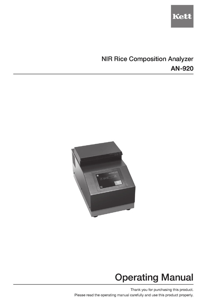
Kett KB-230 User manual

NIR Moisture Analyzer
KB-230
Operating Manual
Thank you for purchasing this product.
Please read the operating manual carefully and use this product properly.


Contents
1. For safety measurement...................................................................... 4
2. Features and part names..................................................................... 6
2-1. Features ............................................................................................................... 6
2-2. Parts of main unit ................................................................................................. 6
2-3. Accessories.......................................................................................................... 7
3.Specications....................................................................................... 8
4. Description of operation keys............................................................. 9
5. Preparing the main unit ....................................................................... 10
6. Specifying measuring conditions....................................................... 11
6-1. Selecting the sample cell (container) ................................................................... 11
6-2. Deciding whether to use the light shielding cover................................................ 12
6-3. Deciding whether to rotate the rotation table ....................................................... 12
6-4. Setting the sampling amount ............................................................................... 13
7. Making the calibration curve............................................................... 14
7-1. Setting the measurement range and the number of samples.............................. 14
7-2. Setting the sampling times................................................................................... 14
7-3. Preparing the samples ......................................................................................... 15
7-4. Moisture preparation ............................................................................................ 15
7-5. Measuring the standard moisture content............................................................ 15
7-6. Optical measurement (entering the calibration data) ........................................... 16
7-7. Calculationofcalibrationcurvecoefcient .......................................................... 18
8. Making measurements......................................................................... 19
9. Zero calibration .................................................................................... 20
10.Setup ..................................................................................................... 21
11. Communication .................................................................................... 26
11-1. Printer output........................................................................................................ 26
11-2.Computer interface .............................................................................................. 26
12.Maintenance.......................................................................................... 27
13.Error display ......................................................................................... 28

4
Improper use of the NIR moisture analyzer in violation of the following safety notes may result in death, injury or
damagetopropertyduetore,etc.Whilethesafetyoftheproducthasbeengivenconsiderableattention,read
the precautions in the operating manual and use the instrument properly.
■Observe the safety precautions.
Read the precautions noted in the operating manual.
The safety measure of the unit may be impaired if instructions are ignored during use.
■Do not use if broken.
Ifyoususpectaproblemormalfunctionintheunit,contactthevendor,ortheKettTokyoofcesalesdivision,alocalbranch
orsalesofce.
■Meaning of warning symbols
In order to prevent damage resulting from erroneously operating the equipment, the following symbols are indi-
cated in the operating manual and on the product.
The following describes their meanings.
Warning Failure to observe these items may lead to death or injury to the user.
Caution Failure to observe these items may lead to injury to the user or damage to property.
Note Items which the user should be aware of in order to use the unit safely.
●Donotusetheunitinaplacewhereexplosive,inammablegas,orliquidsubstanceexists.
Otherwise,itmaycauseexplosion,re,orelectricshock,etc.
●Do not use other than rated power supply voltage.
Ifovervoltageisapplied,theunitwillbeheatedanditmaycausemalfunction,re,orelectricshock.
●Make sure to ground the power cable.
Withthe2Poutlet,useaconversionplugtoground.
Inthecaseof3P,itwillbeautomaticallygrounded.Ifnotgrounded,itmaycausereorelectricshock.
●If any of the cables including the power cable is damaged (broken), do not use it.
Otherwise,itmaycausereorelectricshock,etc.Forpurchasingthespareparts,contactthevendor,
ortheKettTokyoofcesalesdivision,alocalbranchorsalesofce.
●Ifyouseerecomingfromtheunitornoticesmoke,anoddsmell,oranyothersignofabnormalfunc-
tioning, turn off the power and remove the power plug from the outlet, or take whatever measures that
wouldbeappropriatetodealwiththeproblem.Otherwise,itmaycausereorelectricshock,etc.
●Do not attempt to disassemble or modify the unit.
Otherwise,itmaycausemalfunction,re,orelectricshock,etc.Ifyoubelievetheunitmaybemalfunc-
tioning,contactthevendor,ortheKettTokyoofcesalesdivision,alocalbranchorsalesofce.
●Do not allow the unit to come in contact with water.
The infrared moisture tester is not waterproof. Do not allow water or other liquids to get into the unit's
enclosure as this may lead to electric shock or malfunction.
Warning
1. For safety measurement
Fire hazard
Prohibition symbolsCaution symbols Symbols requiring user action
Burn hazard Electric shock hazard
Prohibited
Do not
disassemble
Do not expose
to water
Required
action
Disconnect plug
from electrical
outlet
Grounding

5
●Do not damage, heat, or place heavy object on the power cable or connectors.
Otherwise,itmaycausereorelectricshock,etc.
●Whenconnectingwithotherdevices,rst,turnoffthepowerofeachunit.
●Do not connect/disconnect the power plug with wet hands. Otherwise, it may cause an electric
shock, etc.
●In the maintenance work, remove the plug from the outlet for safety. Otherwise, it may cause an
electric shock.
●To disconnect the plug or connector, make sure to hold the plug or connector, not to pull on the
cable.
Operating environment for safety use
This product is designed to be used safely in the following conditions.
Make sure of the operating environment before use.
●Indoor use
●Altitude: up to 2000 m
●Temperature: 5 to 35°C
●Relative humidity: environmental temperature up to 31°C, max. 80%; at 35°C, max. 65%
●Powersupplyvoltageuctuation:within10%ofnominalvoltage
●Transient overvoltage: within the Overvoltage Category II (conforms to IEC60664-1:2007)
●Pollution Degree 2 (conforms to IEC60664-1:2007)
Installation and storage
●Avoid using or storing the unit in a location where it would be exposed to excessively high or low
temperatures, high levels of humidity, direct sunlight, electromagnetic interference, corrosive gases,
or large amounts of dust.
●Placetheunitonaatandstablesurfacewhereitwillnotbesubjectedtosignicantvibrationdur-
ing use.
●Whenmovingtheunit,nevertiltitanymorethannecessary.
●Take care never to drop or bump the unit or otherwise allow it to be subjected to strong shocks or
the application of excessive force.
●Whenremovingthepowercableorothercables,neverpullonthecordorcableandinsteadhold
the plug or cable connector.
●Use the supplied power cable and make sure to connect to the protective earth.
●Do not install the unit in a place where handling the power cable and connectors or turning the pow-
erswitchismadedifcult.
●Install the unit at least 10 cm away from the walls so that the ventilation openings provided on the
rear of the unit are not blocked.
●Whentheunitisnottobeusedoveranextendedperiodoftime,turnoffthepowerandremovethe
power plug from the outlet.
Cleaning
●To clean the surface of the unit, wipe off using a soft dry cloth.
●Do not use abrasive detergent such as paint thinner or benzene when cleaning this product.
●If measurement sample such as powder, grains, or dust gets into gaps between rotation table, re-
move it to prevent malfunction.
Caution
Burn hazard Electric shock hazard

6
2. Features and part names
2-1. Features
This unit measures the near-infrared absorption of the measuring object, and converts the obtained
data to the moisture.
It uses the measurement principal totally different than drying method or Karl Fischer method.
2-2. Parts of main unit
<Front>
<Rear>
Power switch
Fuse replacing holder
Power supply connector
Printer port
USB portVentilation opening
Light shielding cover
(Accessories are attached)
Rotation table
Measurement
window
Display and operation

7
2-3. Accessories
Sample cell holder
(For petri dish, 90mm)
Power cable
Operating manualFirst guideLight shielding cover
Spare fuseZero-adjustment plate
Petri dish (90mm)
(Sample cell)

8
3.Specications
Measurement method : Near-infraredreection(lterspectroscopy)
Light source : Tungsten lamp
Measuring diameter : approximately ø25 mm
Number of wavelength : 3
Channel number :50
I/O connector : USB, Printer output
Display format : Organic EL
Display content :Channel number, Channel name, Moisture, Absorbance
Operating temperature range : 5 to 35°C (no condensation)
Power supply : 100 - 120V AC/220 - 240V AC (50/60Hz)
Power consumption :50W
Dimensions and weight : 415mm(W)x370mm(D)x230mm(H),11kg
Maximum sampling amount :2kg
Maximum diameter of sample : 150 mm (when using rotation table)Rotation table rotation error
Accessories : Petri dish 90 mm (sample cell), Sample cell holder for Petri dish
90 mm, Zero-adjustment plate, Spare fuse, Power cable, Light
shielding cover, First Guide, Operating Manual
Options : PC software, USB cable VZC-61, Printer VZ-800 (printer cable
VZC-54, papers, AC adapter, and AC cord included)

9
4. Description of operation keys
Operation key Description
[MENU] key Used for setting up and making a calibration curve.
[ENTER] key Used to determine the currently selected item.
[MEA.] key Used for measurement.
[TABLE] key Used to set ON/OFF of the rotation table.
[ZERO] key Used for zero-adjustment.
[CALC.] key Used for a making calibration curve.
[EXIT] key Used to exit the operation.
[MODE] key Used to select the measurement mode.
[CH] key Used to change the channel.
[扌]/[➡] key Used to scroll (up/down) the display.
Numeric keypad Used for entering values or characters.
[clear] key Used for cancelling entered values or characters.

10
5. Preparing the main unit
* Clean the measurement window. If it is not clean, measurement may not be performed correctly.
* Whenclosing/openingthelightshieldingcover,becarefulnottopinchthengers.
⑤Turn on the power switch.
Turn on the power switch located at the rear of the
unit.
⑥Warm up the unit.
Whentheunitispoweredon,therotationtablewill
automatically start rotating to warm-up. At the same
time, a message "SET THE STD PL." will be dis-
played. Set the zero-adjustment plate if it was not set
in step (4).
Whenthewarm-upisdone(after5to6minutes),the
indication"WARMINGUP"turnsoffandthezero-cali-
bration screen will be displayed.
⑦Perform zero-adjustment.
Press the [ENTER] key to execute zero-adjustment.
The zero-adjustment will proceed while displaying
theabsorbanceinreal-time.Whenthecalibrationis
completed, the initial screen will be restored.
* If the power is cycled, repeat the operation from step (6).
Make sure that the zero-adjustment plate is set.
①
Install the main unit.
Installtheunitinaplacewheredirectsunlightisavoidedandnotbesubjectedtosignicantvibration.
②
Attach the light shielding cover.
Attach the light shielding cover by inserting the columns provided on the top surface of the unit into the
mounting holes on the cover.
③Connect the power cable.
Connect the main unit and the power cable.
Plug into the socket, and make sure to ground.
④
Attach the zero-adjustment plate.
Open the light shielding cover, and set the zero-adjustment plate onto the rotation table of the unit. Then,
close the cover.
W A R M I N G U P
S E T T H E S T D P L .
Z E R O ▶X 1
ー
0 . 0 0 0 6
X 2
ー
0 . 0 0 0 9
Z E R O X 1 0 . 0 0 0 1
X 2 0 . 0 0 0 2
0 1 0. 0

11
6. Specifying measuring conditions
1. Petri dish
Beans, etc.
For uneven grains, large grains, or grains whose moisture degree
largelyuctuates
• It is reusable.
• A cover can be used. It will reduce the moisture change while storing
the sample.
• The light shielding cover can be used.
• A measurement using the rotation table is possible.
•
Clean and dry is required at every measurement to prevent mixture of samples.
• Carefully handle so as not to break.
* Use an accessory or following Petri dish:
Fine-marked Petri dish, 90 or 150 (TGK)
2. Plastic bag
Flour and papers, etc.
For powders, small grains, sheets, or ones whose moisture degree
largelyuctuates
• The sample can be sealed, and it will reduce the moisture change
while storing the sample.
• The light shielding cover of the unit may not be used.
• The rotation table may not be used.
• Dispose every time to prevent mixture of samples.
• Use the same thickness and material of the plastic bag in making
calibration curve and performing actual measurement.
• In order to achieve precise measurement, avoid measuring the gus-
set or overlapped part and, keep the measuring surface not wrinkled.
* The following plastic bag is recommended:
Material: PE (polyethylene), PP (polypropylene), PE/PA (polyethylene/polyamide)
Thickness: 0.05 mm or more
3. Polyethylene sheet
Rice ball, boiled noodle, and
uncooked noodles, etc.
For large solid that may taint the measurement window
• Dispose every time to prevent mixture of samples.
• Use the same thickness and material of the polyethylene sheet in
making calibration curve and performing actual measurement.
• In order to achieve precise measurement, avoid measuring the over-
lapped and keep the measuring surface not wrinkled.
* The following polyethylene sheet is recommended:
Material: PE (polyethylene), PP (polypropylene), PE/PA (polyethylene/polyamide)
Thickness: 0.05 mm or more
4. Direct placement
Non-fried noodle or rice crackers, etc.
For large solid that will not taint the measurement window
• Caution is required not to scratch or taint the measurement window.
• The sample should not fall off or spilled when it is set.
6-1. Selecting the sample cell (container)
According to the form of the measuring sample, select a sample cell from four types listed in the
following.
* Make sure that the selected one fully covers the measurement window. Also, use the same one in making
calibration curve and actual measurement.

12
←Rotationicon
6-3. Deciding whether to rotate the rotation table
Whenmeasuringunevenshapeofsample,rotatingthesamplewillhelpimproveaveragingaccura-
cy of the measurement values.
Each time the [TABLE] key is pressed, the rotation of the table can be enabled or disabled.
0 1
0 1
* Some sample may not be rotatable. (ex. A large sample, or when the sample moves, etc.)
* When rotating the table using a 90 mm of Petri dish, use the sample cell holder.
* Use caution for falling off of the samples during rotation.
6-2. Deciding whether to use the light shielding cover
The light shielding cover can avoid effects from external light.
It is preferable to use the cover in order to avoid external light.
* Perform measurement closing the light shield-
ing cover if possible.
* The cover may not be usable depending on the
sample cell or sample form. In the case of not
using the cover, it can be removed.

13
6-4. Setting the sampling amount
Put the sample in the sample cell selected in section 6-1 and determine the sampling amount.
* If the sampling amount (sample height) is not consistent, it may affect the absorbance.
* When not using the light shielding cover, determine the sampling amount under the same condition of ex-
ternal light as measurement.
* Use the same amount in making calibration curve and measurement.
①Set the absorbance measurement mode.
Enter the absorbance measurement mode by pressing the [MODE] key.
(→8. Measurement (P.19))
Immediately before performing this operation, it is recommended to perform zero-adjustment.
(→9. Zero-adjustment (P.20))
0 1 X 1 0 . 0 0 0 1
X 2 0 . 0 0 0 2
②Measure the absorbance.
Measure the absorbance after setting the sample to the sample cell selected in the previous
section 6-1.
0 1 X 1 0 . 9 3 4 0
X 2 0 . 7 5 0 8
③Observe the change of absorbance.
Asthesampleisgraduallyraised,theuctuationofdisplayedabsorbance,X1andX2,willbe-
come stable at a point where the near-infrared pass-through is stopped. Consider the sampling
amount at this point as "absorbance saturated sampling amount". If the sampling amount is
sufcientlyprepared,setthesamplingamountmorethanthe"absorbancesaturatedsampling
amount".
Sampling
amount
Sampling
amount
Sampling
amount
Near-infraredNear-infrared
Sampling
amount
Absorbance
* Refer to P.29, if the absorbance saturated sampling amount cannot be prepared.
When the sample height is raised, there will be a point
where the near-infrared pass-through is stopped.
Then, the value will become stable. Consider the
pointwhereonlythelast2digitsofabsorbanceuc-
tuate as the absorbance saturated sampling amount.
X1 1.0345.....1.0357
X2 0.9531.....0.9523
While the near-infrared from the bottom passes
through the sample, the displayed value will contin-
uetouctuate.
X1 0.8765.....0.9987....1.0015
X2 0.7890.....0.8345....0.9376
Ex:
Ex:
No more change in raising the height of sample

14
7. Making the calibration curve
7-1. Setting the measurement range and the number of samples
Set the moisture range and the number of samples required for making calibration curve.
The samples with different moisture that fully covers the measurement range are required.
* If samples cannot be prepared in the regular moisture control process (drying or adding water), refer to section
7-4 Moisture preparation.
* The larger number of samples will make better reliability of the calibration curve. It is recommended to prepare
morethanvesamples.Atleastthreesamplesarerequiredtomakeacalibrationcurve.
* The measurement result obtained from outside of the moisture range used in making calibration curve will not
be reliable.
* The moisture of the samples should be balanced in the measurement range.
7-2. Setting the sampling times
Set the sampling times per moisture.
Generally,threetovetimesisappropriate.However,iftheshapeofsampleisnotconsistent,seta
larger number.
●Necessity of calibration curve
The infrared moisture analyzer measures the near-infrared absorption of the meas-
uring object, and converts the obtained data to the moisture. Therefore, a conver-
sion formula that calculates actual moisture from near-infrared absorption is re-
quired. This is called "calibration curve". The calibration curve differs depending on
the measuring object. Therefore, it is required to make calibration curve per object
in advance. This unit is capable of making calibration curve easily.
Moisture
Target moisture range Higher than the maximum
moisture range to be measured
The sample for making calibration curve
should cover from 1 to 5 equally.
Lower than the minimum
moisture range to be measured
12345
Ex.) Preparing 5 samples

15
7-4. Moisture preparation
If samples to fully cover the measurement range cannot be prepared in the regular moisture control
process (drying or adding water), prepare the samples by moisture preparation.
To derive a sample with different moisture by moisturising or drying a source sample is called
"moisture preparation". There are various ways to change the moisture content, such as spraying
water using an atomizer or drying the high moisture content sample. Make samples with different
moisture by selecting an optimum method according to the measuring object. Also, when samples
aremadebymoisturepreparation,waitvetosevendaysuntiladdedwateriswellsoakedtoobtain
better consistency of moisture. Then, perform measurement following the next section "7-5 Stand-
ard moisture content" and "7-6 Optical measurement".
7-5. Measuring the standard moisture content
Precisely measure a part of each sample in the over-drying method or the like.
Then, consider the obtained moisture data as the standard moisture content. Set this value in step (5)
of "7-6 Optical measurement".
* Theofcialmethodorameasurementusinganinfraredmoistureanalyzerisavailable.
* Note that the sample cannot be reused if moisture is measured in the over-drying method.
* Ifthesamplingamountisnotsufcientorwhenperformingthemeasurementofstandardmoisturecontent
and actual measurement using the same samples, perform the optical measurement described in "7-6 Opti-
calmeasurement"rst,thenmeasurethestandardmoisturecontent.
Moisture
50g x 4 times + 20g =
220g
50g x 4 times + 20g =
220g
50g x 4 times + 20g =
220g
50g x 4 times + 20g =
220g
50g x 4 times + 20g =
220g
7-3. Preparing the samples
The sampling amount set in section 6-4 is represented as A.
The sampling times set in section 7-2 is represented as B.
At least the sampling amount of Ax Bper moisture is required.
Prepare enough samples to be used in the measurement of standard moisture content (section 7-5)
as well.
Ex) Sampling amount A..................................................50 g
Sampling times B................................................ 4 times
For measurement of standard moisture content .......20 g
* Inthiscase,220gofsampleisrequiredpermoisture.
Intotalof5differentmoisturesamples,1,100gisrequired.

16
1st
sample
7-6. Optical measurement (entering the calibration data)
■Set the main unit. (⇒5. Preparing the main unit (P.10))
■Perform measurement under the same condition in making calibration curve and regular measure-
ment.
Following the procedures below, enter the channel names and sample calibration data obtained in
section 7-1 to 7-5. The calibration data consists of standard moisture content and absorbance. The
absorbance can be obtained automatically by performing the optical measurement, or it can be direct-
ly input using the numeric keypad.
* Justpriortothisoperation,itisrecommendedtoperformzero-adjustment.(→9.Zero-adjustment(P.20))
Step Display Operation
①
P A S S ? _ _ _ _ ●Pass code input
Press the [MENU] key and enter the pass code using the
numeric keypad.
* At the time of shipment, "9999" is set.
Refer to "Setting the pass code" (P.25).
②
1 . C H P A R A M E T E R ▶
2 . C H D U P L I C A T E
3 . C A L I B R A T I O N ▶
4 . C H R E S E T
●Select the menu (calibration).
The menu screen will be displayed.
* Pressing the [EXIT] key will restore the initial screen.
Press the [➡] key twice. Move the cursor over "3. CALI-
BRATON", and press the [ENTER] key.
③
3 . 0 1 ▶
0 2 ×
●Select the channel number.
The channel selection screen will be displayed.
Using [扌]/[➡] key, move the cursor to the channel number
to which the calibration curve is to be registered. Then,
press the [ENTER] key.
* Pressing the [EXIT] key will restore the menu screen.
* Referring to "Channel status icon" (P.18), avoid overwriting
data unintentionally.
④
0 1
N A M E ? ◀ ▶
0 1
N A M E ? ◀F L O U▶
0 1
N A M E ? ◀F L O U R ▶
●Enter the channel name.
The channel name input screen will be displayed.
(The cursor is at the left end.)
Input the channel name from the 1st character using the
numeric keypad moving the cursor one by one with the
[Enter] key.
Up to 6 characters can be entered.
After input is done, move the cursor to the right end [▶]
using the [ENTER] key. Press the [ENTER] key to set the
channel name.
⑤
0 1 N 0 1 C O N T E N T ?
◀ ▶
0 1 N 0 1 C O N T E N T ?
◀1 3 . 1 ▶
●Enter the standard moisture content.
The standard moisture content input screen will be dis-
played.
Input the 1st standard moisture content using the numeric
keypad. Then, move the cursor to the right end [▶] with the
[ENTER] key.
The standard moisture content can be left blank and input
later.
Press the [ENTER] key again, and complete the input of
standard moisture content.
* The standard moisture content can be left blank and input
later. Refer to "7-5 Standard moisture content" (P.15).
Channel 01 What is the standard moisture
content?

17
Step Display Operation
⑥
0 1 N 0 1 X 1 ◀ ▶
M E A X 2 ◀ ▶
0 1 N 0 1 X 1 ◀0 . 5 4 5 6 ▶
M E A X 2 ◀0 . 5 1 1 5 ▶
●Input the absorbance.
The absorbance input screen will be displayed.
To automatically obtain absorbance by optical measure-
ment, set the sample on the measurement window, and
press the [MEA.] key,
The absorbance will be input automatically.
(If measurement is failed, press the [MEA] key again to
retry.)
To directly input the absorbance, or to edit data, use the
numeric keypad.
Move the cursor to the right bottom [▶], and press the [EN-
TER] key.
⑦
0 1 N 0 1 N E X T . N = 0 2 ▶
S A V E . E X I T
0 1 N 0 1 N E X T . N = 0 3 ▶
S A V E . E X I T
・・・・・
●Enter the standard moisture content and absorbance
of 2nd and later samples.
Press the [ENTER] key when "NEXT, N=2" is displayed
after 1st input is done.
Repeat steps (5), (6), and (7) to enter the following points.
⑧
0 1 N 0 5 N E X T . N = 0 6 ▶
S A V E . E X I T
0 1 N 0 5 S A V E . E X I T ▶
C A N C E L . E X I T
●Save the calibration data.
Whenthestandardmoisturecontentofallsamplesare
input, select [SAVE.EXIT] with [➡] key.
The calibration data will be saved when the [ENTER] key is
pressed while [SAVE.EXIT] is selected.
* Note that if the [ENTER] key is pressed while [CANCEL.EXIT]
is selected, the input calibration data will not be saved.
⑨
3 . 0 1 F L O U R
∨
▶
0 2 ×
●Complete the calibration data input.
The check mark icon will be displayed in the channel
selection screen.
Proceedto"Calculatingcoefcient"(P.18)
* Referring to "Channel status icon" (P.18), avoid overwriting
data unintentionally.
<Entering standard moisture content in the later process>
The icon may be displayed.
Operate step (1) to (4), and then enter the standard moisture
content in step (5).
If you press the [ENTER] key twice when entering the absorb-
ance in step (6), you can go to next step without changing the
absorbance.

18
7-7. Calculatingcoefcient
From the calibration data input from the optical measurement described in the section 7-6, calculate the
regressionofcoefcient.
Step Display Operation
①
3 . 0 1 F L O U R
∨
▶
0 2 ×
●Select the channel number and calculate the regression.
Perform (1) to (2) described in P.16.
Using [扌]/[➡] key, move the cursor to the channel number
to which the calibration curve is to be registered.
Make sure that the check mark icon is displayed, and
press the [CALC.] key.
②
3 . 0 1 r : 0 . 9 9 9 5 5
S e : 0 . 0 3 3 2 0
●Check the result of regression calculation.
Thecalculationisinternallyexecuted.Whentheresultis
displayed, scroll with [扌]/[➡] key and check the result.
• Regressioncorrelationcoefcient→r
• Standarderrorofregression→Se
• Coefcient→a0,a1,a2
③
3 . 0 1 S A V E ▶
N 0 5 C A N C E L
●Registerthecoefcient.
Move the cursor to [SAVE] with [扌]/[➡] key, and press the
[ENTER]key.Thecoefcientwillberegistered.
* Thecoefcientwillnotbesaved,ifthe[ENTER]keyis
pressed with [CANCEL] selected with [扌]/[➡]key.
④
3 . 0 1 F L O U R ▶
0 2 ×
●Completeregistrationofcoefcient.
Whenthecoefcientisregistered,theiconturnsoffand
the measurement will be ready.
* When the [CALC.] key is pressed while selecting the channel
number with no icon, the calculation result can be displayed
and checked.
[Channel status icon]
When changing the measurement channel, or during setup, the following icon will be displayed in the channel selection screen.
Icon Measurement Calculatingcoefcient Status
× ×
Calibrationdataisnotinput,ordataisinsufcient.
(For making calibration curve, at least three or more calibration data is
required.)
×○
Effectivecoefcientisnotset.
(The main unit updated the calibration data, but the calculation is not
done.)
(No icon) ○×Effectivecoefcientisset.
* Iftheeffectivecoefcientissetinanyofthefollowingmethod,themeasurementisready(noiconisdisplayed).
• SettingtheeffectivecoefcientusingPCsoftware
• Settingtheeffectivecoefcientreferringto"Settingthechannelparameter"(P.22)
• Makingtheeffectivecoefcientreferringto"7-7Calculatingcoefcient"(P.22)
* When changing the measurement channel, the channel with the icon or cannot be selected.
* Making calibration curve is available with any icon status (channel can be selected while making a calibration curve). How-
ever,thecalibrationdataorcoefcientmayhavebeeninputevenwhenthechannelnameisblank.Usecautioninselecting
a channel when making a calibration curve.
7-8. Calibration curve calculation
Setting offset value and slope correction value will enable correction of measurement value.
Moisture value (displayed moisture) after correction =
Moisture value before correction x Slope correction value + Offset value
* For how to set the offset value and slope correction value, refer to the items described in "Setting the channel
parameter" (P.23).

19
8. Making measurements
Measure the sample in the same measurement condition as making calibration curve. (⇒6. Setting
the measurement conditions (P.11))
* It is recommended to perform zero-adjustment. (⇒9. Zero-adjustment (P.20))
<Step 1>
●Select the channel number.
In the initial screen, select the channel operating [CH.], [扌], [➡], and [ENTER] keys.
<Step 2>
●Select the measurement mode.
Press the [MODE] key and select the measurement mode.
There are three modes: normal measurement mode, continuous measurement mode, and absorb-
ance display mode.
8-1. Normal measurement mode
Following step 1 and 2, select the normal measurement mode.
0 1 0. 0
F L O U R
Set the sample and press the [MEA.] key. The moisture will be displayed after measurement.
* Setthenumberofdisplaydigitsandthenumberofmeasurementasrequired.(⇒Setting the channel pa-
rameter (P.22))
8-2. Continuous measurement mode
Following step 1 and 2, select the continuous measurement mode.
0 1 13. 0
F L O U R
The continuously measured moisture will be displayed regardless of whether the sample is set.
* Setthenumberofdisplaydigitsandsmoothingasrequired.(⇒Setting the channel parameter (P.22))
8-3. Absorbance display mode
Following step 1 and 2, select the absorbance display mode.
0 1 X 1 0 . 5 4 5 6
F L O U R X 2 0 . 5 1 1 4
The continuously measured absorbance will be displayed regardless of whether the sample is set.
* Setthesmoothingasrequired.(⇒Setting the channel parameter (P.22))

20
9. Zero calibration
●What is zero-adjustment?
Iferrorsoccurinthemeasurementresults,readtheabsorbanceobtainedfromreection
on the zero-adjustment plate. The measurement result will be stabilized by setting the
absorbance as zero.
Make sure to perform this operation when making calibration curve or in the regular
measurement as well.
Also, the zero-adjustment is required after the power is turned on.
If performing zero-adjustment without cycling the power, operate the following:
①Attach the zero-adjustment plate.
Open the light shielding cover, and set the zero-adjustment plate onto the rotation table of
the unit. Then, close the cover.
②Perform zero-adjustment.
Press the [ZERO] key. The zero-adjustment screen will be displayed.
Z E R O ▶X 1 0 . 0 0 0 1
X 2 0 . 0 0 0 2
Press the [ENTER] key. The zero-adjustment will be started.
Whenthezero-adjustmentiscompleted,theinitialscreenwillberestoredautomatically.
0 1 0. 0
F L O U R
Table of contents
Other Kett Measuring Instrument manuals