PEUGEOT ACI -100 Instruction manual

r
ACI 100
Anti theft with
transponder
GB
WORKSHOP DOCUMENTATION

r
CONTENTS
INTRODUCTION
page ..........................................................................................................................2
DESCRIPTIONOFTHESYSTEM
page ..........................................................................................................................3
- Operating principle
- Memorisation of the system
PROCEDUREFORMEMORISINGTHEKEYS
page ..........................................................................................................................4
- Checking memorisation
- Erasing the keys from memory
SPECIFICINSTRUCTIONS
page ..........................................................................................................................5
- 1. Loss or destruction of the master key
- 2. Loss or destruction of one black key
- 3. Remplacing the key contact switch
- 4. Remplacing the ACI 100 unit
- Precautions for use
FAULT FINDING ON THE ACI 100 IGNITION SYSTEM
page ..........................................................................................................................6
- Principle of fault finding
- Que faire en cas de panne
DIAGNOSTIC LED TRANSPONDEUR
page ..........................................................................................................................7
- Lighting up of the LED without the ignition key
- Lighting up of the LED when turning on ignition with the Master key
- Lighting up of the LED when turning on ignition with a black key
FAULTFINDINGTABLE
page...........................................................................................................................8
CHECKINGTHEIMMOBILISERUNIT
page...........................................................................................................................9
BLOCKDIAGRAM
page.........................................................................................................................10
1

r
INTRODUCTION
rThis new anti-theft ignition with integrated code through recognition
of a transponder is of variable mapping type.
rThis new unit has the same appearance for all vehicles.
rTheadvance curve depends on the type ofvehicleinwhich the system
is installed:
- 50 cc - 100 cc - 2 stroke
- 125 cc - 4 stroke
rA label stuck to the unit is to inform us of this advance curve and
enables us to check that ACI 100 unit is suitable for that vehicle.
rThisignitionsystemworkswithoutaspecificignitioncoilintheflywheel
magnetoorthealternator.Itispoweredbyacontinuousorrectifiedcurrent:
- Either by the battery
- Or by the battery charge output of the rectifier regulator
rThe new ACI 100 ignition unit facilitates the starting up of the vehicles
for it only needs a minimum voltage to work, lower than that needed for
other ignition systems.
rIt is one of the elements that enables us to respect the future anti-
pollution standards.
2

r
DESCRIPTION OF THE SYSTEM
rThetransponderelectronicimmobiliser isananti-theftsystemwhich prevents starting the vehicleif
anelectroniccode is not supplied to the immobiliser unit.
rThis electronic code is given by a transponder located in the body of the ignition key and does not
requireany specific operation by theuser.
rThesystem consistsof:
-A transponder (integrated into theignitionkey)
-An antenna(locatedaround thekey contact switch)
-AnACI 100 ignition unit
-An LED (located in theinstrumentpanel), as a deterrent functionandfor diagnosis.
OPERATING PRINCIPLE
❐TheACI 100 unit generates an electromagnetic fieldtransmittedto the transponder via an antenna
situatedaroundkeycontact switch.Itreceivesthetranspondercode fromthekey andafterrecognisingthis
codeauthorises the ignition ofthe engine.
❐Whenthesystemisonstandby(ignitionoff)aflashingwarninglight(LED)ontheinstrumentpanel
servesas a deterrent function.However,to minimise battery discharging,this warning light goesoutafter
48hours whilst theelectronicimmobiliser system remainsactive.
Disconnectionof the battery, even over alongperiod of time, does not deactivatethesystem.
LIGHTING OF THE LED during NORMAL use
Black ignition
one FLASH per second key light for 0.5 seconds then extinguished
MEMORISATION OF THE SYSTEM
❐Thetwo ignition keys deliveredwith the vehicles arememorisedat the factory onto theACI100 unit
(
a red key, the master key, is used for programming and a black key).
❐The procedure for memorising the keys enables the immobiliser unit to learn and to memorise the
transpondercode ofthedifferent keys.
❐Thenumber of keys that canbememorised is:
-Minimum 2(includingMasterkey)
-Maximum 3(includingMaster key)
❐Themaster key (redkey) isthe firstkeyused inthe memorisationprocess. Itbecomesa specifickey
as it enables the memorised black keys to be programmed or erased. It is impossible to deprogramme
thismaster key.
❐After memorisation and as a security measure, the master key must be kept by the owner in a
safe place, andmust not remaininthe vehicle.
3

r
PROCEDURE FOR MEMORISING THE KEYS
(
FOR A NEW ACI 100 UNIT)
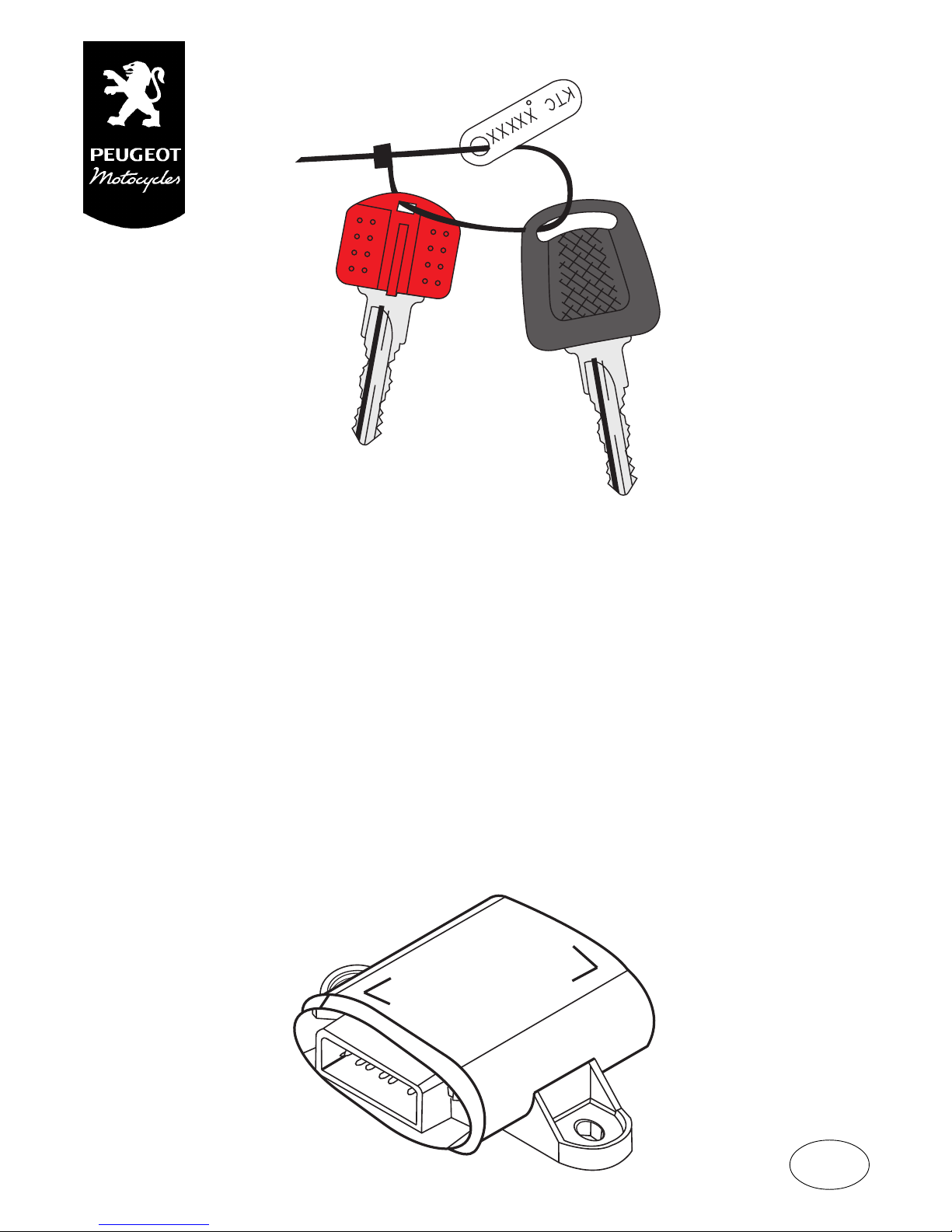
1. Using the master key, put the ignition to ON, as soon as the LED on the instrument panel
lights up, turn off the ignition.
❐The ACI 100 immobiliser unit recognises the transponder of the red key and records it as the
transponderof theFUTURE masterkey.
2. Within a maximum 15 second time period, after having turned off the ignition with the red key,
carry out the operation again with a black key.
(put the ignition to ON, as soon as the LED lights up, turn ignition off).
❐Repeat the operation as many times as there are black keys to be memorised.
(2 maximum)
within a time period no greater than 15 seconds between each key.
3. Still within a maximum time limit of 15 seconds, after turning off the ignition with the last black
key to be memorised, use the red key to turn the ignition ON then turn this off as soon as the LED
lights up.
The ACI 100immobiliser unitrecognises the transponderrecorded in thefirst passage 1.
-It is this second insertion of theredkey that records its transponder as MASTER.
-This operationvalidatesthe procedurefor memorising keys.If this lastoperation is notcarried out
withinthe 15 second time limit, the procedureishalted and has to be restarted fromthebeginning.
- This procedure definitively links the master key and the ACI 100 unit without the possibility of
deprogramming.
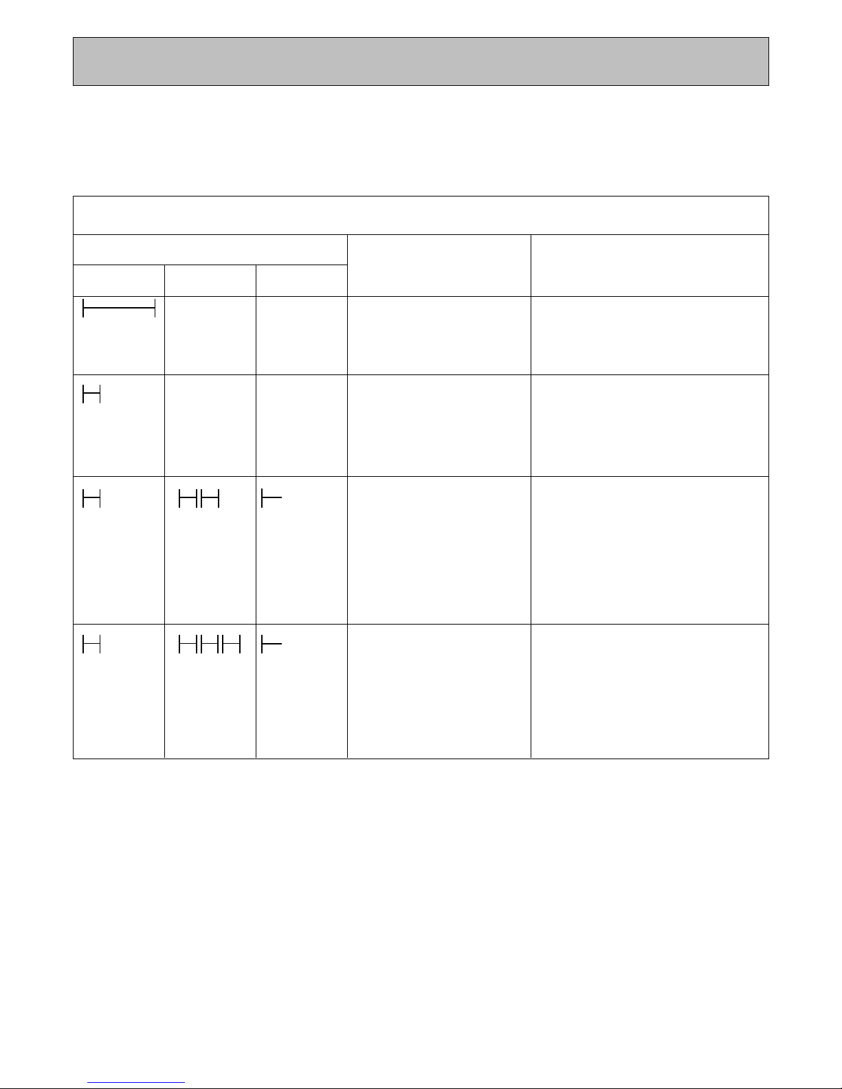
CHECKING MEMORISATION
❐Wait for at least 5 seconds after having turned off the ignition with the master key. Using the
masterkey,switch theignitionon, theLED ontheinstrument panelcomeson forhalf asecondfollowed by
acertain numberofflashes. Thenumber of flashesindicates the numberof keys memorisedincluding the
master key (
red key
): (
2 memorised keys =
2 flashes).
THIS PROCEDURE IS CARRIED OUT AT THE FACTORY FOR
ALL VEHICLES. YOU DO NOT HAVE TO DO THIS ON THE
VEHICLES THAT WE DELIVER TO YOU.
YOU ONLY HAVE TO CARRY OUT THIS OPERATION ON
THE ACI 100 UNITS DELIVERED AS SPARE PARTS
ERASING THE KEYS FROM MEMORY
1. Itis impossible to erase the red key from memory.
2. Erasingthe black key frommemory can only bedonewith the memorisation ofanotherblack key.
4
Redkey 0.5 secflashes flashes

r
SPECIFIC INSTRUCTIONS
1. LOSS OR DESRTUCTION OF THE MASTER KEY
(red key)
❐Lossor destructionofthe master keymakes memorisation orerasingblack keys fromthe memory
impossible.TheACI100immobiliserunitwillenablethevehicletobestartedusingtheblackkeysmemorised
butwiththeriskofthevehiclebeingstolen usingthemaster keyintheeventofitbeinglost.Inorderto make
thesystem safe again, it is compulsory toreplacethe ignition switch and the ACI 100immobiliserunit.
2. LOSS OR DESRUCTION OF THE BLACK KEY
❐In the case of a black key being lost it is impossible to erase it from memory without possessing
anotherblack keyasit isobligatory for memorisation toconsist of ablack key aswell as themaster key.In
order to neutralise the lost key, a blank key has to be ordered from our Spare Parts Service under the
reference753067, thenafter havingreproducedthe shapeof the keyonto thespecificblank havethe new
keymemorised.This will rule outthepossibility of the vehiclebeingstarted usingthelost key.
3. REPLACING THE KEY CONTACT SWITCH
❐Replace the key contact switch. Remove the transponder delivered with the new master key (red
key) and replace it with the transponder fitted in the previous master key. Carry out the memorisation
procedurefor the keys so thattheimmobiliser unit can memorise thenewblack key.
4. REPLACING THE ACI 100 IMMOBILISER UNIT
❐Ifthe immobiliser unitis defective itispossible toreplaceit with anew andblankunit (
notcoded
).It
isnot possible to use a unit from another vehicle fortesting(
unitcoded
).
YOU SHOULD CHECK THAT THE IGNITION WORKS
AT 2000 rpm BEFORE PROGRAMMNG IT !
❐Theprogrammingof thekeysisactuallyirreversible andshouldonlybecarried outwhenitiscertain
thatit is the ACI 100 unit thatisdefective.
❐Programmethe newunitby carryingout the keymemorisation procedure (previouschapter).
PRECAUTIONS FOR USE
❐Theexistence of aninterference suppresser (5KΩresistance) is compulsoryin order for the
systemtofunction.
5

r
FAULT FINDING ON THE ACI 100 IGNITION SYSTEM
PRINCIPLE OF FAULT FINDING
❐The principle is identical to fault finding on a conventional ignition with in addition, diagnostic
possibilitiesgiven by the lighting upofan LED on the instrumentpanel.
WHAT TO DO IN THE EVENT OF A FAULT
1. CHECK THAT A SPARK IS PRODUCED BY THE SPARK PLUG
a)
If sparkis present the problem does not concern the ignition
b)
Ifthere is nospark the problem does concern the ignition
2. CHECK THE LED DIAGNOSIS
a)
The LED shows diagnosis
Refer to the TRANSPONDER LED DIAGNOSIS table
(page 7)
b)
The LED does not function
Checkits wiringconnectionson theinstrument panel:
- Red wire : supply +12Vpermanent supply
-Blue wire : connection to theACI100 ignition unit terminal
(6)
Checkthe LED: connect a 12V supply totheinstrument panel in place of the redandblue wires
(Do not connect the LED alone to the 12V supply. The presence of two protective resistors is
compulsory).
c)
The LED does not supply a diagnosis:
Firstof all check the standardcausesof a fault in theignitionsystem:
-Interruptionin wiring
- Components
(spark plugs, interference suppresser, coils, flywheel…)
-Lastly check the specific ACI 100 ignition components
WARNING
❐
When replacing an ACI 100 ignition unit it is essential to check that the ignition is turnin,g
when idle at (2000 rpm) before going ahead with the key memorisation procedure.
The procedure for memorising the keys creates adefinitive link between the ACI 100 unit and the
master key, which makes it impossible to use them separately.
6

r
DIAGNOSIS BASED ON TRANSPONDER LED
1. LIGHTING UP OF LED WITHOUT THE IGNITION KEY
❐Asuccession of one flash persecondindicates that the vehicle isprotectedagainst theft. (If the
unitis programmed). . . . . (representation of flashes)
❐Thisdeterrent function isoperational for 48 hoursafter switching off theignition.
❐After48 hours the LEDgoesouttoavoid discharging the battery, but theimmobilisersystem
remainsactive.
❐Even in the case of the battery being disconnected the system remains active.
❐Uponreconnection of the battery the memorised keys will allow the car to be started, however
longthe period of disconnection.
2. LIGHTING UP OF LED WHEN TURNING ON IGNTION WITH MASTER KEY.
0.5 sec flashes
❐Lightingup for 0.5 sec followedbya certain number of flashesindicatesthe number of keys
programmed(including the masterkey)2 flashes accordingtothe original configuration.
❐Thenumberof flashes(2minimum–3 maximum)correspondstothenumber ofkeysprogrammed.
2 sec
❐A single lighting up of LED for 2 seconds indicates that the unit is not programmed (to turn at
2000rpmmaximum).
3. LIGHTING UP OF LED WHEN TURNING ON THE IGNITION WITH ONE BLACK
KEY❐Thelighting up of theLED using a blackkeyconsists of three successivephaseswhen turning on
theignition:
Phase 1 : gives information on the state of the system
2 sec = ACI 100 not programmed (key not memorised)
0.5 sec = ACI 100 programmed
Phase 2: gives information concerning the diagnosis.
No lighting up =No faultdetectedon thetransponder system.
0.5 secs = 2 to 3 lighting ups of 0.5 sec: fault detected
(see fault finding table page 8).
Phase 3 : givesinformation concerning authorisation to start
No lighting up =Ignitionauthorised
Permanent lighting up =Allumagenon autorisé,
(see fault finding table page 8)
.7
- - - - - -

r
-Black key not programmed, carry out
programmingprocedure.
- Black key defective, replace the key and
carryout programmingprocedure.
-ACI 100from anothervehicle.
8
LIGHTING UP PHASE OF THE LED INDICATIONS COMMENTS
PHASE 1 PHASE 3PHASE 2
FAULT FINDING TABLE FOR THE ACI 100
BLACK KEY: IGNITION ON POSITION
2sec ACI 100notprogrammed - Turns at 2000 rpm maximum
-Carry outamemorisation procedurefor
the keys.
0.5sec ACI100 programmed - No faults found, starting up possible.
- If starting up impossible, see standard
causesof defectiveignition(wiring, spark
plug, coil etc).
0.5sec 2 X 0.5sec permanent
Transpondernotrecognised - Antenna disconnected or break in the
circuit.Checktheresistanceoftheantenna
which must be at17 ohms at the terminals
of the small connector.
-
Keywithout transponder(
tryanotherkey,
forexampletheMasterKey,replacethekey
ifnecessary
).
0.5sec 3 X 0.5sec permanent
Transpondernotauthorised
- - - - - -
- - - - - -

r
CHECKING THE IMMOBOLISER UNIT
9
VEHICLE ACI 100 UNIT
ENGINE DOES NOT START
CHECKTHE STANDARDCAUSES OFADEFECTIVE IGNITION UNIT
starter motor, fuse(s), spark plug, spark plug wiring, HT coil, interference suppresser, cut wire,
electrical connections, sensor, flywheel magneto, key contact switch….
ENGINE DOES NOT START
TEST NEW ACI 100
(uncoded)
ENGINE DOES NOT START
-REMOVE THE NEW ACI 100UNIT
-REFIT THE VEHICLE’S ACI 100 UNIT
- LOOK FOR THE CAUSE OF THE
FAULT OUTSIDE OF THE
TRANSPONDER SYSTEM
ENGINE STARTS
Maxi 2000 rpm
Carryout key memorisationprocedure
(page 4)

r
BLOCK DIAGRAM
ACI 100 TRANSPONDER WITH DETERRENT LED
10
12V
123
4568
7
1
10
7
White
Red Red
9
c
b
d
ACI 100.01
501703010012
12 V = 254-98
3
560 Ω
236 Ω
8
ON
2
OFF
Yellow/Blue
6
5
4
Green
Green
Yellow/Black
Green
Green
Blue
Black
Red
Red
Red
Red
Yellow/Blue
Red
11
17Ω
Yellow
Yellow
11........00
03/11/1998
1 FlywheelmagnetoGF10
- b sensor
- c alternating
- d batterycharge
2 Key contact switch
3 ACI100ignition unit
4 High tension coil
5 5KΩinterferencesuppresser
6 5KΩresistive sparkplug
7 Regulatorrectifier
8 LEDindicator with protectionresistances
9 12Vbattery
10 Fuse
11 Transponderantenna

r
NOTES

r
recommends
N° 11.754048.00
Intheaim of constantimprovement, Peugeot Motocycles reservesthe right tomodify,deleteor add tothereferences mentioned.
DC/PS/DOC/SHImp.in U.E.I3R 11/10/99 ed1(Noncontractual photos)
Table of contents
Other PEUGEOT Car Alarm manuals