Pfaff Industrial Seam User manual

INSTRUCTION MANUAL
Seam test station
296-12-19 210/002
Betriebsanleitung engl. 03.12

The reprinting, copying or translation of PFAFF Instruction Manuals, whether in whole or
in part, is only permitted with our previous authorization and with written reference to the
source.
PFAFF Industriesysteme
und Maschinen AG
Hans-Geiger-Str. 12 - IG Nord
D-67661 Kaiserslautern

Index
Contents ..................................................................................Page
1Proper use............................................................................................................................. 4
2Specifications ....................................................................................................................... 5
3Disposal of Machine ............................................................................................................ 6
4Explanation of symbols....................................................................................................... 7
5Controls ................................................................................................................................ 8
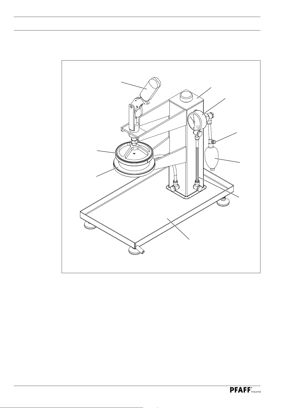
5.01 Summary of controls (Version without pneumatics connection) ........................................... 8
5.02 Summary of controls (Version with pneumatics connection) ................................................ 9
6Preparation ......................................................................................................................... 10
6.01 Setting the test material thickness ...................................................................................... 10
6.02 Filling the water tank ........................................................................................................... 10
7Testing..................................................................................................................................11
7.01 Testing (Version without pneumatics connection) ............................................................... 11
7.02 Testing (Version with pneumatics connection)..................................................................... 12
8Maintenance....................................................................................................................... 13
8.01 Maintenance intervals.......................................................................................................... 13
8.02 Lubrication ........................................................................................................................... 13
8.03 Manometer replacement ..................................................................................................... 13
9Parts list .............................................................................................................................. 14

4
Proper use
1 Proper use
The seam connections, which are sealed with a seam sealing tape, are checked at the seam
test station for water-tightness in accordance with DIN 20811.
The test is conducted for outdoor wear, ski, surfing and diving suits, and for shoes.
Any and all uses of this machine which have not been approved of by the
manufacturer are considered to be inappropriate! The manufacturer cannot be
held liable for any damage caused by the inappropriate use of the machine!
The appropriate use of the machine includes the observance of all operational,
adjustment, maintenance and repair measures required by the manufacturer!

5
Specifications
2 Specifications
Max. clearance underneath test plates:............................................................. approx. 38 mm
Fill water: ............................................................................................................ distilled water
Dimensions:
Length:............................................................................................................. approx. 450 mm
Width: .............................................................................................................. approx. 300 mm
Height .............................................................................................................. approx. 620 mm
Connection data:
Pressure min.:.................................................................................................................... 1 bar
Pressure max.:................................................................................................................... 6 bar
Net weight: ......................................................................................................... approx. 7,1 kg
Gross weight (mit Karton):................................................................................. approx. 11,1 kg

Disposal of Machine
6
3 Disposal of Machine
●Proper disposal of the device is the responsibility of the customer.
●The materials used for the machine are steel, aluminium, brass and various plastic
materials. The electrical equipment comprises plastic materials and copper.
●The device is to be disposed of according to the locally valid pollution control regula-
tions; if necessary, a specialist ist to be commissioned.
Care must be taken that parts soiled with lubricants are disposed of separately
according to the locally valid pollution control regulations!

Arbeitssymbole
7
4 Explanation of symbols
In this instruction manual, work to be carried out or important information is accentuated by
symbols. These symbols have the following meanings:
Note, information
Cleaning, care
Lubrication
Maintenance, repairs, adjustment, service work
(only to be carried out by technical staff)

8
Controls
0
+-
1
0. .8
0. 40.6
Fig. 5 - 01
●Pressure plate 1.
●Clamping plate 2.
●Material clamping lever 3.
●Water tank 4.
●Manometer 5.
●Bleeder screw 6.
●Pump bellow 7.
●Water level display 8.
●Water collection tank 9.
5 Controls
5.01 Summary of controls (Version without pneumatics connection)
2
4
5
6
7
1
9
3
8

9
Controls
Fig. 5 - 02
0
+-
1
0. .8
0. 4 0 .6
●Pressure plate 1.
●Clamping plate 2.
●Material clamping lever 3.
●Water tank 4.
●Air stop cock 5.
●Pressure regulator 6.
●Manometer 7.
●Water level display 8.
●Water collection tank 9.
5.02 Summary of controls (Version with pneumatics connection)
2
345
6
7
1
9
8

10
Preparation
●Screw on union nut 1.
●Insert the plastic plate or the lattice
supplied depending on the material, and
screw in place with the union nut 1.
●Loosen counter nut 2 and set the
material thickness to be processes by
turning the clamping plate 3.
The material thickness should
be set in such a way that no
water can escape during the
test process while the clamping
lever 4 is engaged, but also that
the material is not marked with
pressure marks.
0
+-
1
0. .8
0. 40.6
Fig. 6 - 01
1
6 Preparation
6.01 Setting the test material thickness
2
4
●Unscrew screw 1 from water tank 2.
●Fill the tank 2 with water, while ensuring
that it cannot escape from the pressure
plate 3.
●Replace the screw 1.
Only use distilled water to
prevent lime scale build-up.
Fig. 6 - 02
1
2
3
6.02 Filling the water tank
3

Prüfen
11
0
+-
1
0. .8
0. .6
Fig. 7 - 01
●Place the material for testing underneath the clamping lever 1 and press down on the
lever 2.
●Close bleeding screw 3.
●Generate the desired test pressure via the pump bellow 4.
Open the bleeding screw 3 after the test process to depressurise the system.
●Release the lever 2 and remove the material.
1
7 Testing
7.01 Testing (Version without pneumatics connection)
2
3
4

Prüfen
12
0
+-
1
0. .8
0. 40.6
Fig. 7 - 02
7.02 Testing (Version with pneumatics connection)
2
3
4
●Place the material for testing underneath the clamping plate 1 and press down on the
lever 2.
●Close the air stop cock 3.
●Connect compressed air at pressure reducer 4.
●Set the desired pressure for testing on the regulating nut 5 of the pressure reducer.
Once the test process has been completed, close the air stop cock 4 to
depressurise the system.
●Release the lever 2 and remove the material.
1-2
2-3
1-2
2-3
33
closed open
5
1

Maintenance
13
Fig. 8 - 01
8.02 Lubrication
0
+-
1
0. .8
0. 40.6
1
Lubrication ...............................................................................................................annually
Manometer replacement .........................................................................................annually
8 Maintenance
8.01 Maintenance intervals
8.03 Manometer replacement
●The installed manometer has been tested and should be replaced once a year.
●State the item no. 95- 257 523 91 for ordering a tested manometer.
●Lubricate guide 1with a little grease once a year.
Only use Gleitmo 585 M heavy duty grease,
part no. 280-1-120 269.

Parts list
14
9 Parts list
99-137 944-91
95-257 523-91
99-137 945-91
95-257 280-04/001
95-257 299-45
95-257 293-04/001
95-257 297-45
95-257 298-45
99-137 943-91
99-137 942-91 (4x)
95-257 280-04/002
95-257 296-45
95-257 293-04/002
95-257 294-45
95-257 295-45
0
+-
1
0. .8
0. 4 0.6
0
+-
1
0. .8
0. 4 0.6
99-136 187-91
95-257 292-04/001

Note

PFAFF Industriesysteme
und Maschinen AG
Hans-Geiger-Str. 12 - IG Nord
D-67661 Kaiserslautern
Phone: +49 - 6301 3205 - 0
Fax: +49 - 6301 3205 1386
E-mail: info@pfaff-industrial.com
Hotlines:
Technical service: +49 - 175/2243-101
Application consultance: +49 - 175/2243-102
Spare-parts hotline: +49 - 175/2243-103
Printed in Germany
© PFAFF Industriesysteme und Maschinen AG 2009, PFAFF is the exclusive trademark of VSM Group AB.PFAFF Industriesysteme und Maschinen AG is an authorized licensee of the PFAFF trademark.
Table of contents
Popular Test Equipment manuals by other brands

Hakko Electronics
Hakko Electronics FG-460 instruction manual

Fluke Biomedical
Fluke Biomedical DPM1B Operator's manual

Huazheng
Huazheng HZ-9003C manual

AMO
AMO STU-20 manual

Dwyer Instruments
Dwyer Instruments TDS Series Specifications - Operating Instructions

Extech Instruments
Extech Instruments PRT200 user guide