MPS MP5515 User manual

User Guide
MP5515 Evaluation Kit (EVKT-5515)
2
MP5515 Evaluation Kit User Guide rev 1.0
MonolithicPower.com
7/17/2018
MPS Proprietary Information. Patent Protected. Unauthorized Photocopy and Duplication Prohibited.
© 2018 MPS. All Rights Reserved.
USER GUIDE –MP5515 EVALUATION KIT (EVKT-5515)
Table of Contents
Overview................................................................................................................................................ 3
Section 1. Hardware Specifications........................................................................................................5
1.1 Personal Computer Requirements.............................................................................................. 5
1.2 EV5515-U-00A Specifications.....................................................................................................5
1.3 EVKT-USBI2C-02 Specifications................................................................................................ 5
Section 2. Software Requirements......................................................................................................... 6
2.1 Software Installation Procedure.................................................................................................. 6
Section 3. Evaluation Kit Test Set-Up..................................................................................................... 7
3.1 Hardware Set-Up........................................................................................................................7
3.2 Powering up the EVB ................................................................................................................. 7
3.3 Software Set-Up......................................................................................................................... 7
3.4 Troubleshooting Tips............................................................................................................... 11
Section 4. Ordering Information............................................................................................................ 12
3
MP5515 Evaluation Kit User Guide rev 1.0
MonolithicPower.com
7/17/2018
MPS Proprietary Information. Patent Protected. Unauthorized Photocopy and Duplication Prohibited.
© 2018 MPS. All Rights Reserved.
USER GUIDE –MP5515 EVALUATION KIT (EVKT-5515)
Overview
Introduction
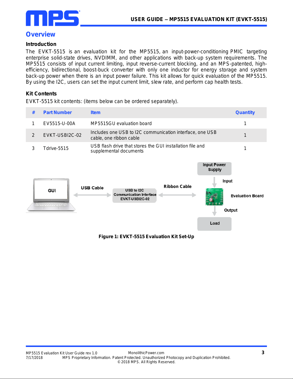
The EVKT-5515 is an evaluation kit for the MP5515, an input-power-conditioning PMIC targeting
enterprise solid-state drives, NVDIMM, and other applications with back-up system requirements. The
MP5515 consists of input current limiting, input reverse-current blocking, and an MPS-patented, high-
efficiency, bidirectional, boost-buck converter with only one inductor for energy storage and system
back-up power when there is an input power failure. This kit allows for quick evaluation of the MP5515.
By using the I2C, users can set the input current limit, slew rate, and perform cap health tests.
Kit Contents
EVKT-5515 kit contents: (items below can be ordered separately).
#
Part Number
Item
Quantity
1
EV5515-U-00A
MP5515GU evaluation board
1
2
EVKT-USBI2C-02
Includes one USB to I2C communication interface, one USB
cable, one ribbon cable
1
3
Tdrive-5515
USB flash drive that stores the GUI installation file and
supplemental documents
1
Figure 1: EVKT-5515 Evaluation Kit Set-Up
Ribbon Cable
4
MP5515 Evaluation Kit User Guide rev 1.0
MonolithicPower.com
7/17/2018
MPS Proprietary Information. Patent Protected. Unauthorized Photocopy and Duplication Prohibited.
© 2018 MPS. All Rights Reserved.
USER GUIDE –MP5515 EVALUATION KIT (EVKT-5515)
Features and Benefits
The MP5515 is highly customizable. Users can program the PMIC via the MPS I2C GUI.
All changes made in I2C mode will NOT be retained once the EVB is powered down.
Features adjustable under each method are outlined below.
I2C
•
Back-up capacitor health test
•
10-bit A/D converter to measure the input voltage, input current, backup voltage,
and TEMP pin temperature sensor voltage discharge (DISCHG)
•
Back-up boost enable
•
Adjustable input current limit and ISOFET current limit
•
Adjustable VB ramp-up slew rate
•
Adjustable buck switching frequency
•
VIN recover control
•
Status indication via 10-bit A/D converter (VIN to the VB current limit, input over
voltage, storage voltage, power good, high temperature and over temperature
warning)
•
Interrupt mask control
•
Adjustable temperature warn threshold
•
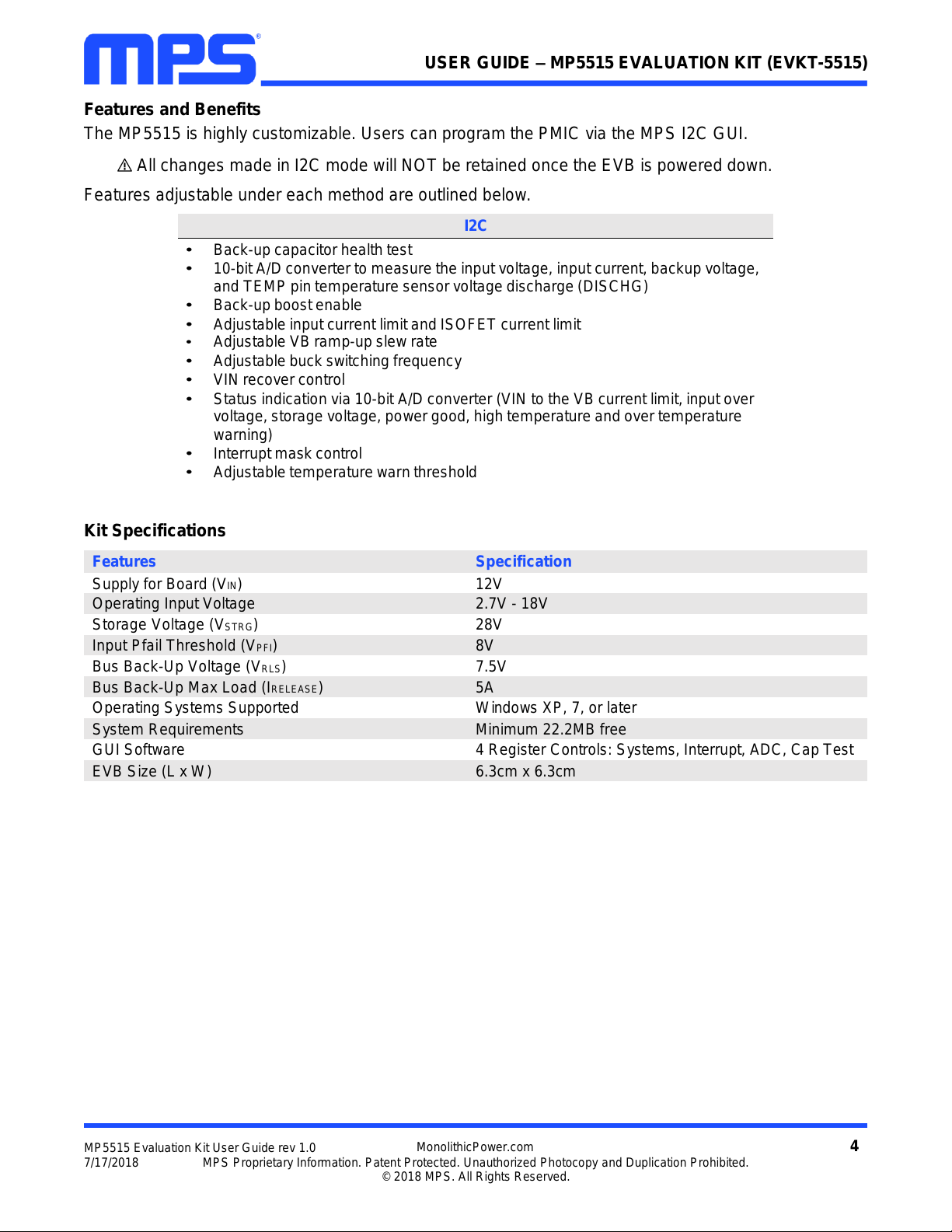
Kit Specifications
Features
Specification
Supply for Board (VIN)
12V
Operating Input Voltage
2.7V - 18V
Storage Voltage (VSTRG)
28V
Input Pfail Threshold (VPFI)
8V
Bus Back-Up Voltage (VRLS)
7.5V
Bus Back-Up Max Load (IRELEASE)
5A
Operating Systems Supported
Windows XP, 7, or later
System Requirements
Minimum 22.2MB free
GUI Software
4 Register Controls: Systems, Interrupt, ADC, Cap Test
EVB Size (L x W)
6.3cm x 6.3cm

5
MP5515 Evaluation Kit User Guide rev 1.0
MonolithicPower.com
7/17/2018
MPS Proprietary Information. Patent Protected. Unauthorized Photocopy and Duplication Prohibited.
© 2018 MPS. All Rights Reserved.
USER GUIDE –MP5515 EVALUATION KIT (EVKT-5515)
Section 1. Hardware Specifications
1.1 Personal Computer Requirements
The following must be minimally met to use the EVKT-5515.
•
Operating System of Windows XP, 7, or later
•
Net Framework 4.0
•
PC with a minimum of one available USB port
•
At least 22.2 MB of free space
1.2 EV5515-U-00A Specifications
The EV5515-U-00A is an evaluation board for the MP5515GU. For more information, please refer to
the EV5515-U-00A datasheet.
Figure 2: EV5515-U-00A Evaluation Board
1.3 EVKT-USBI2C-02 Specifications
The EVKT-USBI2C-02 refers to the communication interface, which connects the EVB, the PC, and its
supporting accessories. It provides I2C and PMBus capabilities. Together with MPS Virtual Bench Pro
and GUI tools, it provides a quick and easy way to evaluate the performance of MPS digital products.
For more details, refer to the EVKT-USBI2C-02 datasheet.
Figure 3: EVKT-USBI2C-02 Communication Interface
Feature
Specification
Supply for Evaluation Board
12V
Operating Input Voltage
2.7V - 18V
Storage Voltage (VSTRG)
28V
Input Pfail Threshold (VPFI)
8V
Bus Back-Up Voltage (VRLS)
7.5V
Bus Back-Up Max Load (IRELEASE)
5A
EVB Size (L x W)
6.3cm x 6.3cm

6
MP5515 Evaluation Kit User Guide rev 1.0
MonolithicPower.com
7/17/2018
MPS Proprietary Information. Patent Protected. Unauthorized Photocopy and Duplication Prohibited.
© 2018 MPS. All Rights Reserved.
USER GUIDE –MP5515 EVALUATION KIT (EVKT-5515)
Section 2. Software Requirements
2.1 Software Installation Procedure
Programming occurs through the MPS I2C GUI. Follow the instructions below to install the software.
Note: In the near future, this software can be downloaded from the MPS website. For now, it is provided
on a USB thumb drive.
1. Plug the thumb drive into the computer using any available USB port.
2. Locate the folder containing the thumb drive contents.
3. Double click the .exe file to open the set-up guide (see Figure 4).
4. Follow the prompts in the set-up guide.
5. Wait for the status screen to verify that installation is complete (see Figure 5).
Figure 4: MPS I2C GUI Set-Up Guide
Figure 5: MPS I2C GUI Set-Up Success
7
MP5515 Evaluation Kit User Guide rev 1.0
MonolithicPower.com
7/17/2018
MPS Proprietary Information. Patent Protected. Unauthorized Photocopy and Duplication Prohibited.
© 2018 MPS. All Rights Reserved.
USER GUIDE –MP5515 EVALUATION KIT (EVKT-5515)
Section 3. Evaluation Kit Test Set-Up
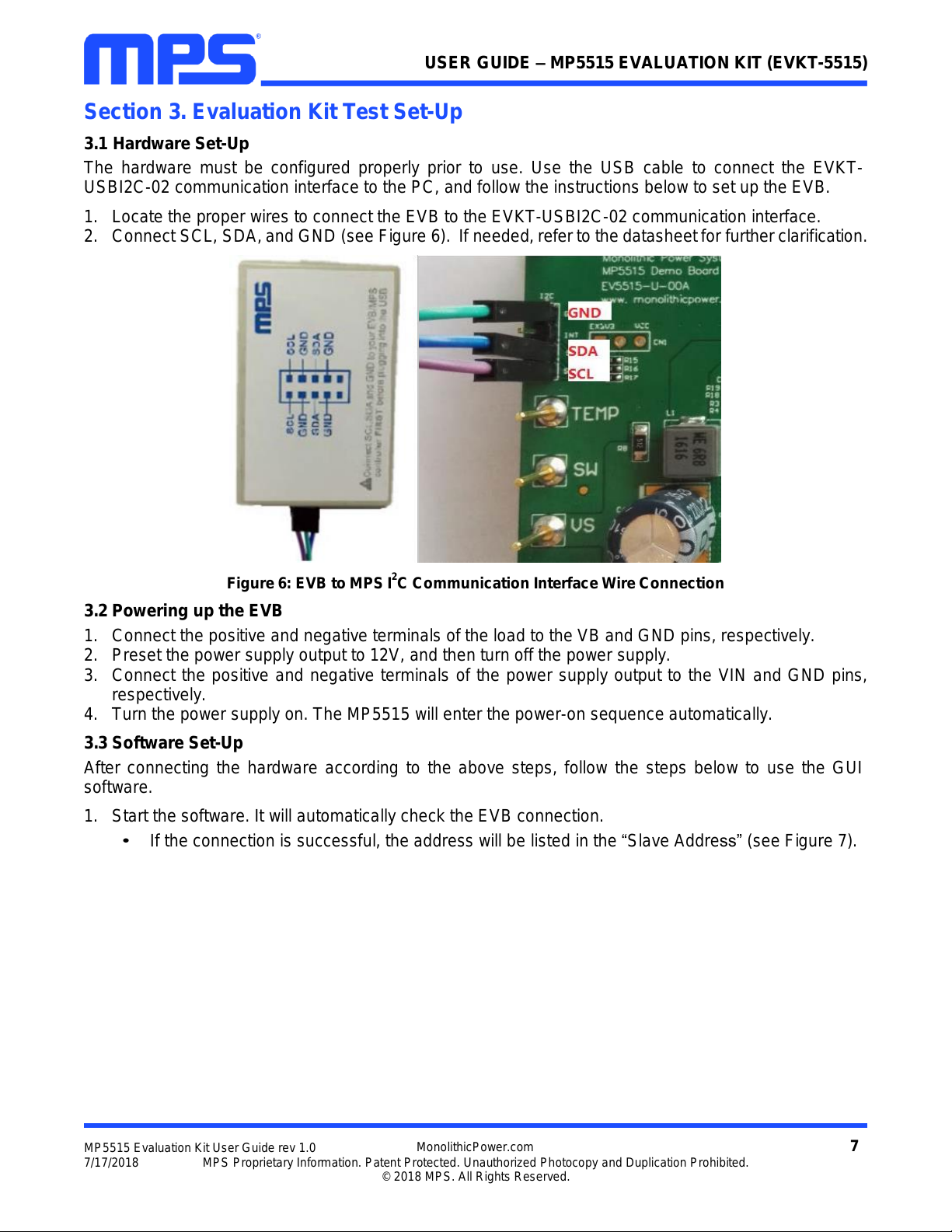
3.1 Hardware Set-Up
The hardware must be configured properly prior to use. Use the USB cable to connect the EVKT-
USBI2C-02 communication interface to the PC, and follow the instructions below to set up the EVB.
1. Locate the proper wires to connect the EVB to the EVKT-USBI2C-02 communication interface.
2. Connect SCL, SDA, and GND (see Figure 6). If needed, refer to the datasheet for further clarification.
Figure 6: EVB to MPS I2C Communication Interface Wire Connection
3.2 Powering up the EVB
1. Connect the positive and negative terminals of the load to the VB and GND pins, respectively.
2. Preset the power supply output to 12V, and then turn off the power supply.
3. Connect the positive and negative terminals of the power supply output to the VIN and GND pins,
respectively.
4. Turn the power supply on. The MP5515 will enter the power-on sequence automatically.
3.3 Software Set-Up
After connecting the hardware according to the above steps, follow the steps below to use the GUI
software.
1. Start the software. It will automatically check the EVB connection.
•
If the connection is successful, the address will be listed in the “Slave Address” (see Figure 7).

8
MP5515 Evaluation Kit User Guide rev 1.0
MonolithicPower.com
7/17/2018
MPS Proprietary Information. Patent Protected. Unauthorized Photocopy and Duplication Prohibited.
© 2018 MPS. All Rights Reserved.
USER GUIDE –MP5515 EVALUATION KIT (EVKT-5515)
Figure 7: Appearance of Address Shows Successful Connection
•
If not, a warning will appear at the bottom. There are two warnings users can expect.
1) “No Slave Found. Please Check the Connection!”This means that the evaluation board is
not connected (see Figure 8).
2) “Device is not available. Please check the Connection!”This means that the USB I2C
communication interface is not connected (see Figure 9).
Figure 8: Warning Indicates Unsuccessful Connection –Evaluation Board not Connected
No Slave Found, Please check the connection!

9
MP5515 Evaluation Kit User Guide rev 1.0
MonolithicPower.com
7/17/2018
MPS Proprietary Information. Patent Protected. Unauthorized Photocopy and Duplication Prohibited.
© 2018 MPS. All Rights Reserved.
USER GUIDE –MP5515 EVALUATION KIT (EVKT-5515)
Figure 9: Warning Indicates Unsuccessful Connection –USBI2C Communication Interface not Connected
2. If the connection is successful, proceed to Step 3. Otherwise, check connections between the EVB,
communication interface, and PC. Re-plug the USB into the computer and restart the GUI.
3. Select the MP5515 under Part Numbers. The Register Control menu will appear on the left side.
I2C register values will be read and displayed on the right side after clicking the Read All button
(see Figure 10).
Figure 10: Values from I2C Shown in Table
Device is not available. Please check the Connection!

10
MP5515 Evaluation Kit User Guide rev 1.0
MonolithicPower.com
7/17/2018
MPS Proprietary Information. Patent Protected. Unauthorized Photocopy and Duplication Prohibited.
© 2018 MPS. All Rights Reserved.
USER GUIDE –MP5515 EVALUATION KIT (EVKT-5515)
4. Find the item you want to change and select the desired value from the drop-down menu.
5. Click the Read All button to update values. The changed information of the item will appear on the
right side (see Figure 11).
Figure 10: Refer to Datasheet to Translate 0’s and 1’s
All changes made via I2C will be restored to default values once the EVB is powered down.
11
MP5515 Evaluation Kit User Guide rev 1.0
MonolithicPower.com
7/17/2018
MPS Proprietary Information. Patent Protected. Unauthorized Photocopy and Duplication Prohibited.
© 2018 MPS. All Rights Reserved.
USER GUIDE –MP5515 EVALUATION KIT (EVKT-5515)
3.4Troubleshooting Tips
Note: USBI2C-02 and USBI2C-01 drivers are not compatible. USBI2C-02 uses USBXpress and
USBI2C-01 uses Cyusb3. USBI2C-02 is the recommended device for MPS PMBus and I2C.
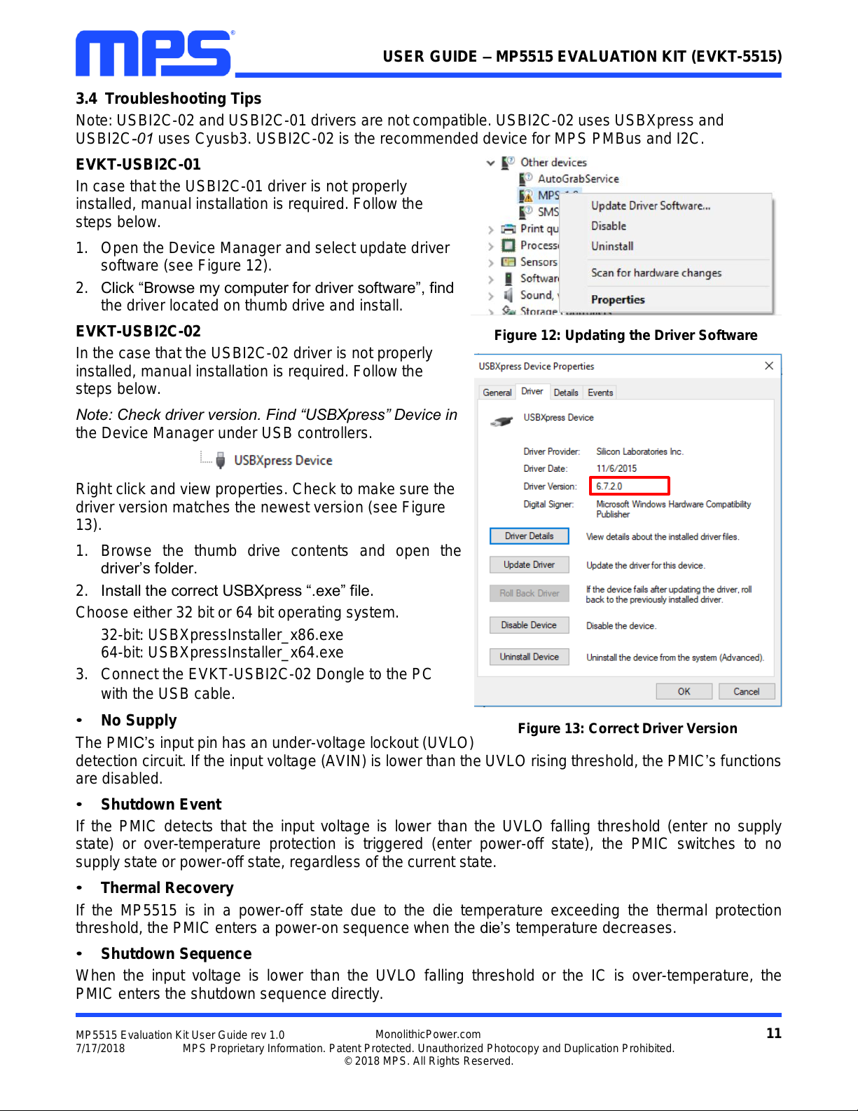
EVKT-USBI2C-01
In case that the USBI2C-01 driver is not properly
installed, manual installation is required. Follow the
steps below.
1. Open the Device Manager and select update driver
software (see Figure 12).
2. Click “Browse my computer for driver software”, find
the driver located on thumb drive and install.
EVKT-USBI2C-02
In the case that the USBI2C-02 driver is not properly
installed, manual installation is required. Follow the
steps below.
Note: Check driver version. Find “USBXpress” Device in
the Device Manager under USB controllers.
Right click and view properties. Check to make sure the
driver version matches the newest version (see Figure
13).
1. Browse the thumb drive contents and open the
driver’s folder.
2. Install the correct USBXpress “.exe” file.
Choose either 32 bit or 64 bit operating system.
32-bit: USBXpressInstaller_x86.exe
64-bit: USBXpressInstaller_x64.exe
3. Connect the EVKT-USBI2C-02 Dongle to the PC
with the USB cable.
•
No Supply
The PMIC’s input pin has an under-voltage lockout (UVLO)
detection circuit. If the input voltage (AVIN) is lower than the UVLO rising threshold, the PMIC’s functions
are disabled.
•
Shutdown Event
If the PMIC detects that the input voltage is lower than the UVLO falling threshold (enter no supply
state) or over-temperature protection is triggered (enter power-off state), the PMIC switches to no
supply state or power-off state, regardless of the current state.
•
Thermal Recovery
If the MP5515 is in a power-off state due to the die temperature exceeding the thermal protection
threshold, the PMIC enters a power-on sequence when the die’s temperature decreases.
•
Shutdown Sequence
When the input voltage is lower than the UVLO falling threshold or the IC is over-temperature, the
PMIC enters the shutdown sequence directly.
Figure 13: Correct Driver Version
Figure 12: Updating the Driver Software

12
MP5515 Evaluation Kit User Guide rev 1.0
MonolithicPower.com
7/17/2018
MPS Proprietary Information. Patent Protected. Unauthorized Photocopy and Duplication Prohibited.
© 2018 MPS. All Rights Reserved.
USER GUIDE –MP5515 EVALUATION KIT (EVKT-5515)
Section 4. Ordering Information
The components of the evaluation kit can be purchased separately depending on user needs.
Part Number
Description
EVKT-5515
Complete evaluation kit
Contents of EVKT-5515
EV5515-U-00A
MP5515GU evaluation board
EVKT-USBI2C-02
Includes one USB to I2C communication interface, one USB cable,
one ribbon cable
Tdrive-5515
USB thumb drive that stores the GUI installation file and supplemental
documents
Order directly from MonolithicPower.com.
Other manuals for MP5515
1
This manual suits for next models
1
Table of contents
Popular Test Equipment manuals by other brands

Kyoritsu Electrical Instruments Works, Ltd.
Kyoritsu Electrical Instruments Works, Ltd. KEW 1700 instruction manual

AutoTest
AutoTest Euro Trailer Socket Tester user manual

Unit
Unit UT15A instruction manual

Unit
Unit utd2000 operating manual

digi-tech
digi-tech QC-1936 user manual

AOK
AOK CellMeter 8 User guide and manual


