Owon VDS1022l User manual

Mar. 2015 edition V1.4.4
Copyright © Lilliput Company. All rights reserved.
The Lilliput's products are under the protection of the patent rights, including ones which have already obtained the patent rights and those which are applying for. The information
in this manual will replace all that in the materials published originally.
The information in this manual was correct at the time of printing. However, will continue to improve products and reserves the rights to change specification at any time
without notice.
is the registered trademark of the Lilliput Company.
Fujian Lilliput Optoelectronics Technology Co.,Ltd.: The Mansion of Optoelectronics, No.19, Heming Road, Lantian Industrial Zone, Zhangzhou, Fujian, China
Tel:+86-596-2130430 Fax:+86-596-2109272
Web: www.owon.com Mail: [email protected]om.cn

General Warranty
Lilliput warrants that the product will be free from defects in materials and workmanship for a period of 3 years from the date of purchase of the product by
the original purchaser from the Lilliput Company. And the warranty period of accessories such as probe is 12 month. This warranty only applies to the
original purchaser and is not transferable to the third party. If the product proves defective during the warranty period, Lilliput either will repair the defective
product without charge for parts and labor, or will provide a replacement in exchange for the defective product. Parts, modules and replacement products
used by Lilliput for warranty work may be new or reconditioned to like new performance. All replaced parts, modules and products become the property of
Lilliput.
In order to obtain service under this warranty, Customer must notify Lilliput of the defect before the expiration of the warranty period. Customer shall be
responsible for packaging and shipping the defective product to the service center designated by Lilliput, and with a copy of customer proof of purchase.
This warranty shall not apply to any defect, failure or damage caused by improper use or improper or inadequate maintenance and care. Lilliput shall not be
obligated to furnish service under this warranty a) to repair damage resulting from attempts by personnel other than Lilliput representatives to install, repair
or service the product; b) to repair damage resulting from improper use or connection to incompatible equipment; c) to repair any damage or malfunction
caused by the use of non-Lilliput supplies; or d) to service a product that has been modified or integrated with other products when the effect of such
modification or integration increases the time or difficulty of servicing the product.
Please contact the nearest Lilliput's Sales and Service Offices for services or a complete copy of the warranty statement.
For better after-sales service, please visit www.owon.com and register the purchased product online.
Excepting the after-sales services provided in this summary or the applicable warranty statements, Lilliput will not offer any guarantee for maintenance definitely declared or
hinted, including but not limited to the implied guarantee for marketability and special-purpose acceptability. Lilliput should not take any responsibilities for any indirect,
special or consequent damages.

i
Table of Contents
VDS Oscilloscope Software Help......................................................................................................................................................... ii
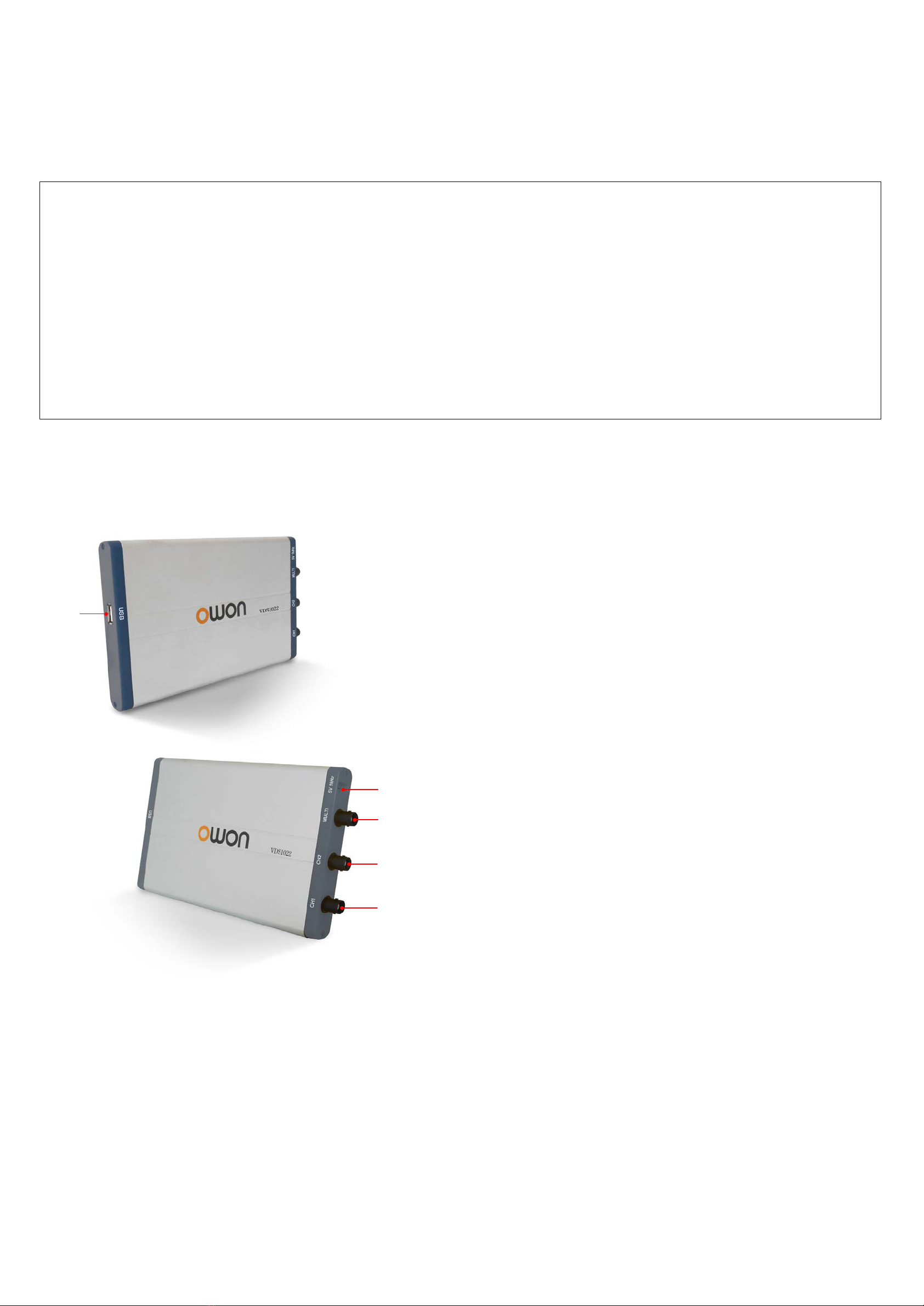
Ports Introduction.....................................................................................................................................................................ii
VDS1022(I)/ VDS2052(I) ..................................................................................................................................................................................................ii
VDS2062(L)/VDS3102(L)................................................................................................................................................................................................iii
VDS2064(L)/VDS3104(L)................................................................................................................................................................................................iii
General Safety Requirements................................................................................................................................................iv
Safety Terms and Symbols .................................................................................................................................................... iv
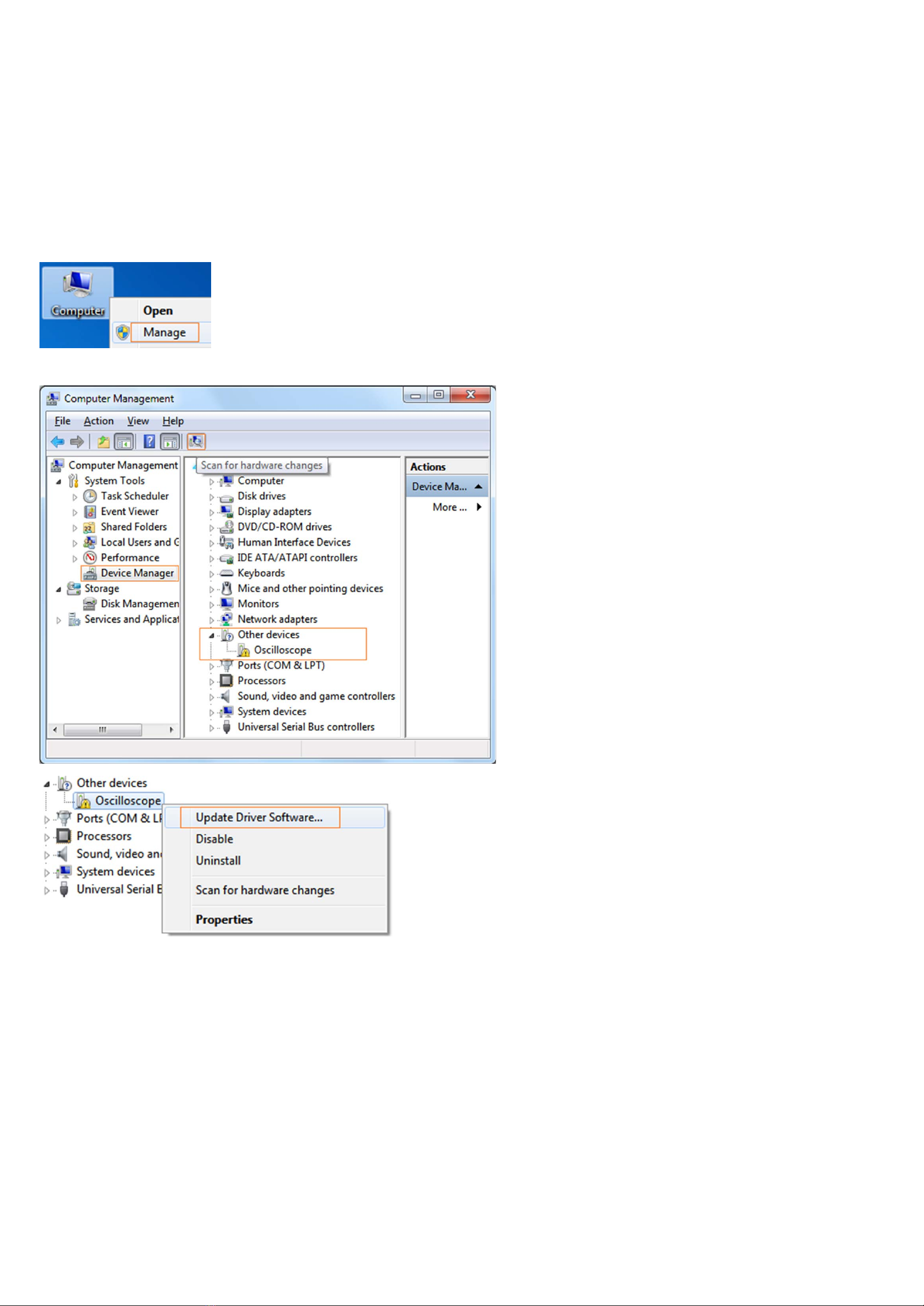
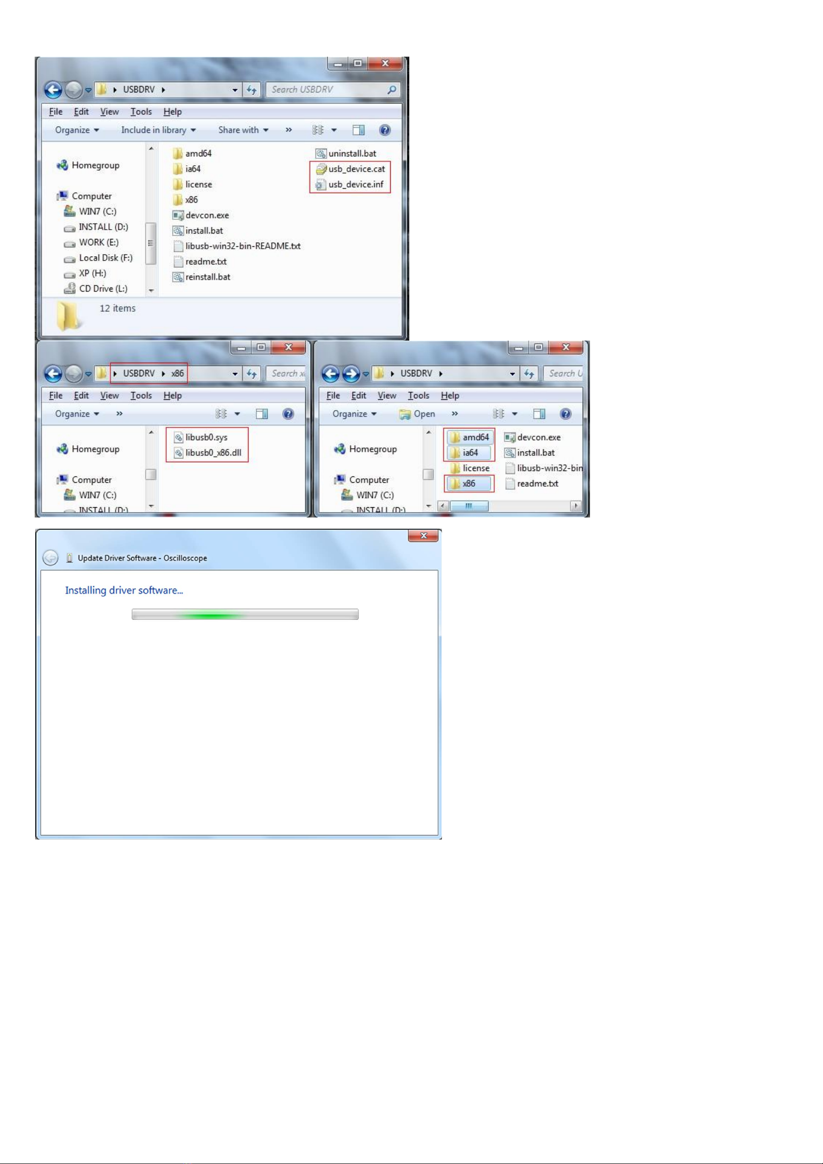
I. PC Software USB Driver Install Guide................................................................................................................................1
For Windows Vista\Windows 7\Windows 8................................................................................................................................................................... 1
For Windows XP\Windows 200....................................................................................................................................................................................... 5
II. User Interface........................................................................................................................................................................9
III. Operations Instruction......................................................................................................................................................11
1.How to Set the Probe Attenuation Coefficient......................................................................................................................................................... 11
2.How to Set the Vertical System................................................................................................................................................................................. 11
3.How to Set the Horizontal System............................................................................................................................................................................ 12
4.How to Set the Trigger System.................................................................................................................................................................................. 12
5.How to Set the Channels............................................................................................................................................................................................ 14
6.How to Measure Automatically.................................................................................................................................................................................. 15
7.How to Implement Sampling Setup........................................................................................................................................................................... 16
8.How to Measure with Cursors.................................................................................................................................................................................... 17
9.How to Set the Display System................................................................................................................................................................................. 19
10.Use Mathematical Manipulation Function.............................................................................................................................................................. 20
11.How to zoom the waveform...................................................................................................................................................................................... 23
12.How to do Pass/Fail test........................................................................................................................................................................................... 24
13.How to Record and Play a Waveform.................................................................................................................................................................... 25
14.How to Implement the Utility setting....................................................................................................................................................................... 26
15.How to Use Executive Buttons................................................................................................................................................................................ 29
16.Use LAN Port ............................................................................................................................................................................................................. 29
IV. Technical Specifications ..................................................................................................................................................33

ii
VDS Oscilloscope Software Help
Welcome to VDS Oscilloscope software.
The supplied accessories of the oscilloscope include a Quick Guide. The Quick Guide of the oscilloscope and the following helps are for your
reference.
Minimum PC Requirements
Processor: Pentium(R) 4 2.4 GHz
Memory: 1 GB
Disk space: 1 GB minimum
Recommended PC Requirements
Processor: Pentium(R) Dual-Core 2.4 GHz
Memory: 2 GB
Disk space: 1 GB minimum
Other Requirements
Operating system: Windows XP(32-bit & 64-bit), Windows Vista(32-bit & 64-bit), Windows 7(32-bit & 64-bit), Windows 8(32-bit & 64-bit)
Ports: USB 2.0, USB 1.1
Display Resolution: 1024 x 768
Ports Introduction
VDS1022(I)/ VDS2052(I)
1
3
4
5
2
Figure Ports of the Oscilloscope(take VDS1022 for instance)
1. USB port: Supply power by PC USB or the adapter; communicate with PC
2. Probe Compensation: Measurement signal (5 V/1 kHz) output
3. MULTI port: EXT trigger input, trigger output or Pass/Fail output
4. Signal input of Channel 2
5. Signal input of Channel 1
Note: VDS1022(I) represents two types of machines, they are VDS1022I and VDS1022. VDS1022I contains isolation, while VDS1022 does not
contain isolation. The same as VDS2052(I).

iii
VDS2062(L)/VDS3102(L)
1
2
4
5
6
3
Figure: Ports of the Oscilloscope (take VDS3102(L) for instance)
1. USB port: Supply power by PC USB or the adapter; communicate with PC
2. LAN port (optional): Network port which can be used to connect with PC
3. Probe Compensation: Measurement signal (3.3 V/1 kHz) output
4. MULTI port: EXT trigger input, trigger output or Pass/Fail output
5. Signal input of Channel 2
6. Signal input of Channel 1
VDS2064(L)/VDS3104(L)
1
3
4
5
7
8
6
9
2
Figure: Ports of the Oscilloscope (take VDS3104(L) for instance)
1. Probe Compensation: Measurement signal (3.3 V/1 kHz) output
2. MULTI Connector (optional): Connect Q9 cable with the MULTI port
3. MULTI port: EXT trigger input, trigger output or Pass/Fail output
4. LAN port (optional): Network port which can be used to connect with PC
5. USB port: Supply power by PC USB or the adapter; communicate with PC
6. Signal input of Channel 4
7. Signal input of Channel 3
8. Signal input of Channel 2
9. Signal input of Channel 1
Note: If you use LAN port to communicate with PC, the oscilloscope should be powered by the adapter.

iv
General Safety Requirements
Before any operations, please read the following safety precautions to avoid any possible bodily injury and prevent this product or any other products
connected from damage. In order to avoid any contingent danger, this product is only used within the range specified.
Only the qualified technicians can implement the maintenance.
Pay attention to the nominal values of all terminals: To avoid fire or electric shock, please keep a watchful eye on all nominal values and marks specified for this product. Before
any connection performed on this product, carefully read the user's manual of the product for further information of nominal values.
No touch is allowed on bare conductors: When the product is powered on, do not touch any bare joints or parts of the scope meter.
Operation is prohibited in case of any undetermined failure: When in doubt any damage on this product, consult the qualified personnel for checking on it.
Keep ventilation in good condition: Refer to the user manual for detail installation instructions in order to fix this product correctly and provide it with good ventilation conditions.
No operation is allowed under a humid environment.
No operation is allowed under an explosive environment.
Keep clean and dry on the product surface.
The method which stipulated according to the factory does not use the equipment, possibly can damage the protection which the equipment provides.
Safety Terms and Symbols
Safety Terms
Terms in this manual. The following terms may appear in this manual:
Warning: Warning indicates the conditions or practices that could result in injury or loss of life.
Caution: Caution indicates the conditions or practices that could result in damage to this product or other property.
Terms on the product. The following terms may appear on this product:
Danger: It indicates an injury or hazard may immediately happen.
Warning: It indicates an injury or hazard may be accessible potentially.
Caution: It indicates a potential damage to the instrument or other property might occur.
Safety Symbols
Symbols on the product. The following symbol may appear on the product:
Hazardous Voltage
Refer to Manual
Protective Earth Terminal
Chassis Ground
Test Ground

1
I. PC Software USB Driver Install Guide
Use the supplied USB cable to connect the oscilloscope with a PC through their USB ports.
Note: If you use a USB cable that is not supplied by us, some problems such as connection error and signal disturbing might
occur.
For Windows Vista\Windows 7\Windows 8
The Microsoft Windows Systems since Windows Vista, Windows 7 or Windows 8, change a lot, which require a new installation guide of USB driver. Here it is.
During the whole installation, please assure that the device is running well and plugged into PC from USB.
Right click [Computer], you can find it on the desktop, or in [Start] menu.
in the pop up menu, click [Manage] and it will open a window named "Computer Management", as follow, in the left side click [Device Manager], it will show a devices tree in
the middle, and then click the last one button "Scan for hardware changes" in tool bar as follow, and if the device is running well and plugged into PC, computer will detect an
unknown device with a "!" icon.
Right click the unknown device icon, in the pop up menu click [Update Driver Software...],
In the open window, select [Browse my computer for driver software],

2
The next window, select a directory path for the driver software location, and click "Next",
Notice: the driver software location is a directory that is under the software setup folder named "USBDRV" (For Windows 8, the location is USBDRV\USBDRV_win8), and the
contents inside are like these:
Or like this, than you should use the "USBDRV" directory to indicate the ".inf" file, and to the ".sys" or ".dll" file, you can indicate then in different directories like "x86", "ia64" or
"amd64" depending on the CPU, but most of time just x86 and amd64 are enough.

3
OK, back to the driver installing, after last "Next" step, the system is installing driver software for you, as follow,
In the course,
It(for Windows XP x86&x64, Windows Vista x86&x64, Windows 7 x86) may open a window named "Windows Security" as below, and just select "Install this driver software
anyway" to continue,

4
Or sometimes it(for Windows 7 x64) may open a window named "Windows Security" as below, and just click "Install" to continue,
And then continue installing,
And finish.
Now a successful installation window opens with information "Windows has successfully updated your driver software".

5
Close the window, have a look at the "Computer Management" window, you will find a device under [LibUSB-Win32 Devices], it should be like this:
Now the USB driver will work.
For Windows XP\Windows 2000
Notice: for both x86 and x64.
Plug into the running well device to open [Found New Hardware Wizard] dialog.
Or you can right click [My Computer] and select [Manage], in the left area of opened [Computer Management] select [Device Manager] , double click the item [USB Device]
with "?" in the middle area to open the Wizard,

6
In the Wizard, select [No, not this time] ,
select [Install from a list or specific location(Advanced)] ,
select [Search for the best driver in these locations.] , then select [Include this location in the search] and indicate a directory location for USB driver which is named as
"USBDRV" and under the directory where you installed the program at,

7
Then the installation is running,
And complete,
And prompt as installed,
And show installed in [Device Management],

8
Now you can use the program and use if for USB communication.
If there is an early version of USB driver in your computer, you could try running "reinstall.bat" to fix, the file is under the directory of "USBDRV".

9
II. User Interface
1.
Waveform Display Area
2.
Display status, click to choose "Disconnect", "Install USB Driver" or "Connect LAN". Refer to the
instruction of the status after this list.
3.
The red pointer indicates the horizontal position for the trigger
4.
The pointer indicates the trigger position in the internal memory
5.
Measure time with cursors
6.
The two yellow dotted lines indicate the size of the viewing expanded window
7.
Auto set, see 15.How to Use Executive Buttons
8.
Run/Stop, see 15.How to Use Executive Buttons
9.
Single Trigger, see 15.How to Use Executive Buttons
10.
Back to Home menu
11.
Hide the menu
12.
Measure voltage with cursors
13.
The red pointer shows the trigger level position for CH1 (yellow for CH2). It can be dragged up and down.
14.
Function menu, click to show/hide
15.
Shortcut icon of resetting to factory settings, see "Default"
Shortcut icon of exporting waveform, see "Pause&Export"
Switch Three View/One View. In the Three View display mode, the left top is XY mode widow, the
right top is FFT window.
Show/hide Function menu
16.
Trigger window, see 4.How to Set the Trigger System
17.
Sample and Period window, see 3.How to Set the Horizontal System
18/19.
Channel window of CH2 and CH1, see 2.How to Set the Vertical System
20.
Display the measured type and value of the corresponding channel, see 6.How to Measure Automatically
21.
Cursor measure window, see 8.How to Measure with Cursors
22/23.
The yellow pointer shows the grounding datum point (zero point position) of the CH2 waveform. If the
pointer is not displayed, it means that this channel is turned off. (Red pointer is for CH1)
24.
The waveform of CH1

10
Keyboard Shortcuts
F5: Run/Stop
Ctrl + Enter: AutoSet
Q: The voltage division of Channel 1 decreases one level
A: The voltage division of Channel 1 increases one level
W: The voltage division of Channel 2 decreases one level
S: The voltage division of Channel 2 increases one level
←: Time base decreases one level
→: Time base increases one level
F1: Open this help document
Instruction of the status information
Auto
Automatic trigger mode
Ready
Ready for a trigger
Trig'd
Has trigged
Scan
Slow scan
Stop
Data acquisition stopped
Error
Error occurred
ReSyncing
Synchronize with the oscilloscope
again
AutoSet
In process of auto setting
The statuses of not staying connected with the oscilloscope:
Offline
No connection with the
oscilloscope
USBFound
Find available USB devices
USBDrvErr
USB drivers installed error
MachineNotSupport
Can not recognize the device
The statuses in the process of connecting with the oscilloscope:
Linking
Being connecting with the
oscilloscope
Connect
connect successfully
Match
Matching the model
Syncing
Sync the settings

11
III. Operations Instruction
Relevant operations of this software.
1.How to Set the Probe Attenuation Coefficient
The probe has several attenuation coefficients, which will influence the vertical scale factor of the oscilloscope.
To change or check the probe attenuation coefficient in the menu of oscilloscope:
(1) Click to show the Function menu, choose "Channel".
(2) Click to select the channel that the probe connects with (CH1 or CH2).
(3) Set "Probe Rate" to the proper value corresponding to the probe.
This setting will be valid all the time before it is changed again.
Caution:
The default attenuation coefficient of the probe in the software is preset to X10.
Make sure that the set value of the attenuat
ion switch in the probe is the same as
the menu selection of the probe attenuation coefficient in the software.
The set values of the probe switch are X1 and X10.
Figure: Attenuation Switch
Caution:
When
the attenuation switch is set to X1, the probe will limit the bandwidth of the
oscilloscope in 5
MHz. To use the full bandwidth of the oscilloscope, the switch
must be set to X10.
2.How to Set the Vertical System
You can set the corresponding parameters of vertical system in the Channel window (18/19 in II. User Interface).
In the voltage division list, you can select the proper value. Take VDS3102(L) for instance.
You can set the zero point position through the control bar to regulate of the vertical display position of the signal. You can also drag the zero
point position pointer (22, 23 in II. User Interface).

12
Drag the slider up to increase, down to decrease; the further from the center, the higher the changing speed is.
Keyboard Shortcuts
Q: The voltage division of Channel 1 decreases one level
A: The voltage division of Channel 1 increases one level
W: The voltage division of Channel 2 decreases one level
S: The voltage division of Channel 2 increases one level
Cymometer
It is a 6-digit cymometer. The cymometer can measure frequencies from 2 Hz to the full bandwidth. Only if the measured channel has triggering
signal and in Edge mode, it can measure frequency correctly. In the Single trigger mode, it is a one channel cymometer and it can only measure
the frequency of the triggering channel. In the ALT trigger mode, it is a two channel cymometer and it can measure the frequency of two
channels.
3.How to Set the Horizontal System
You can set the corresponding parameters of horizontal system in the Capture&period window (17 in II. User Interface).
You can use Horizontal Trigger Position control bar to adjust the horizontal position of the signal in the waveform window. You can also drag the
red pointer to adjust it (3 in II. User Interface).
Note: Different models have different ranges of time base, just take VDS3102(L) for instance here.
The further from the center, the higher the changing speed is.
Keyboard Shortcuts
←:Time base decreases one level
→:Time base increases one level
See also: 11.How to zoom the waveform
4.How to Set the Trigger System
Trigger determines when VDS starts to acquire data and display waveform. Once trigger is set correctly, it can convert the unstable display to
meaningful waveform.
When VDS starts to acquire data, it will collect enough data to draw waveform on left of trigger point. VDS continues to acquire data while waiting
for trigger condition to occur. Once it detects a trigger it will acquire enough data continuously to draw the waveform on right of trigger point.
Click to show Function menu, choose "Trigger".
You can also click in the right bottom window to show it.

13
Trigger Control
The oscilloscope provides two trigger types: single trigger and alternate trigger.
Single trigger: Use a trigger level to capture stable waveforms in two channels simultaneously.
Alternate trigger: Trigger on non-synchronized signals.
The Single Trigger and Alternate Trigger menus are described respectively as follows:
Single trigger
1. In Trigger menu, choose "Single" (the chosen label has a mark).
2. Choose Source.
3. Choose Mode.
Single trigger has four modes: edge trigger, video trigger, slope trigger and pulse trigger.
Edge Trigger: It occurs when the trigger input passes through a specified voltage level with the specified slope.
Video Trigger: Trigger on fields or lines for standard video signal.
Slope Trigger: The oscilloscope begins to trigger according to the signal rising or falling speed.
Pulse Trigger: Find pulses with certain widths.
The four trigger modes in Single Trigger are described respectively as follows:
Edge Trigger
Choose Mode as "Edge". An edge trigger occurs on trigger threshold value of input signal. Select Edge trigger mode to trigger on rising edge or
falling edge.
Set in Trigger menu:
(1) Choose "Rise" to trigger on rising edge.
Choose "Fall" to trigger on falling edge.
(2) Click the voltage value after "Trigger" to show slider bar. You can also drag "13. Trigger point" in II. User Interface .
(3) Choose Trig Mode.
Auto: Acquire waveform even no trigger occurs.
Normal: Acquire waveform when trigger occurs.
Single: When trigger occurs, acquire one waveform then stop.
(4) Set Hold Off: When trigger occurs, acquire one waveform then stop (100ns - 10s).
Setting method: "+", "++", "+++" is the position of digit that will be changed. "+" represents the last digit, "++" represents the middle digit,
"+++" represents the first digit. Eg. When "+" is chosen, click ▲, the last digit will be increased by 1.
Click "Reset" to set Holdoff time as default value (100ns).
Set in Trigger window:
Force: Force to create a trigger signal and the function is mainly used in "Normal" and "Single" mode.
This manual suits for next models
1
Table of contents
Other Owon Test Equipment manuals

Owon
Owon VDS6104P User manual

Owon
Owon PDS series User manual

Owon
Owon VDS6000 Series User manual

Owon
Owon TAO3000 Dual-Channel Series User manual

Owon
Owon PDS6062T User manual

Owon
Owon SDS5032E(V) User manual

Owon
Owon MSO7062TD User manual

Owon
Owon XDS3104A User manual

Owon
Owon VDS Series User manual

Owon
Owon DGE3000 Series User manual

Owon
Owon DSO-2072H User manual

Owon
Owon FDS Series User manual

Owon
Owon SDS series User manual

Owon
Owon XDS3204AE User manual

Owon
Owon SDS-E Series User manual

Owon
Owon HDS2202 User manual

Owon
Owon MSO7102T User manual

Owon
Owon MSO7102TD User manual

Owon
Owon AG4101 User manual

Owon
Owon SDS5052E-V User manual