Pfaff Industrial 8306 User manual

8306
INSTRUCTION MANUAL
296-12-18 659/002
Instruction Manual engl. 11.11

Reprinting, reproduction and/or translation of PFAFF instruction manuals
(including parts thereof) is only permitted with our prior agreement and
citation of the source.
PFAFF Industriesysteme
und Maschinen AG
Hans-Geiger-Str. 12 - IG Nord
D-67661 Kaiserslautern

Table of Contents
Contents ..................................................................................Page
3
1Safety .................................................................................................................................... 5
1.01 Directives............................................................................................................................... 5
1.02 General safety instructions .................................................................................................... 5
1.03 Safety symbols ...................................................................................................................... 6
1.04 Special points of attention for the owner-operator ................................................................ 6
1.05 Operating personnel and technical staff ................................................................................ 7
1.05.01 Operating personnel .............................................................................................................. 7
1.05.02 Technical staff........................................................................................................................ 7
1.06 Danger warnings.................................................................................................................... 8
2Proper Use............................................................................................................................ 9
3Technical Datas................................................................................................................. 10
4Disposal of the Machine.................................................................................................... 11
5Transport, Packaging and Storage ................................................................................... 12
5.01 Transport to the customer's premises ................................................................................ 12
5.02 Transport within the customer's premises.......................................................................... 12
5.03 Disposal of the packaging materials .................................................................................... 12
5.04 Storage ................................................................................................................................ 12
6Work Symbols.................................................................................................................... 13
7Operating Controls ............................................................................................................ 14
7.01 Overview of the operating controls ..................................................................................... 14
7.02 Main switch ........................................................................................................................ 15
7.03 Roller feed of the belt transport .......................................................................................... 15
7.04 Control for the hot air pressure and feed roller pressure .................................................... 16
7.05 Control panel ....................................................................................................................... 16
7.06 Pedals ................................................................................................................................. 17
8Set-up and Initial Commissioning .................................................................................... 18
8.01 Set-up .................................................................................................................................. 18
8.02 Mounting the sealing tape reel bracket ............................................................................... 19
8.03 Connecting the compressed air........................................................................................... 19
8.04 Initial start-up ....................................................................................................................... 20
8.05 Switching the machine on/off.............................................................................................. 20
9Set-up.................................................................................................................................. 21
9.01 Inserting the sealing tape ................................................................................................... 21
9.02 Entering the sealing temperature ....................................................................................... 22
9.03 Entering the sealing speed ................................................................................................. 23
9.04 Further settings ................................................................................................................... 23

Table of Contents
Contents ..................................................................................Page
4
10 Sealing ................................................................................................................................ 24
10.01 Sealing principle................................................................................................................... 24
10.02 Sealing process.................................................................................................................... 24
11 Maintenance and Care....................................................................................................... 25
11.01 Maintenance intervals.......................................................................................................... 25
11.02 Cleaning ............................................................................................................................... 25
11.03 Checking / setting the air pressure ...................................................................................... 25
11.04 Emptying / cleaning the maintenance unit's water tank...................................................... 26
11.05 Fuses ................................................................................................................................... 26
12 Circuit Diagram .................................................................................................................. 27

Safety
5
1 Safety
1.01 Directives
The machine was built in compliance with the European regulations specified in the
conformity declaration and the manufacturer's declaration of conformity. As a supplement
to this instruction manual, please also observe the generally applicable, legal and other
regulations and legislation – also in the country of use – and the valid environmental
protection regulations! Always comply with the locally applicable regulations of the
professional associations and other supervisory authorities!
1.02 General safety instructions
●The machine may only be operated after you have become acquainted with the associ-
ated instruction manual and only by operating personnel who have received appropriate
training!
●Always follow the hazard and safety instructions attached to the machine!
●The machine may only be operated for its intended purpose and only with the associated
safety covers, while adhering to all the relevant safety requirements.
●Isolate the machine by pulling out the mains plug from the power supply when replacing
the feed rollers or hot air nozzle, when leaving the work station and for maintenance and
adjustment work!
●The daily maintenance work may only be carried out by suitably qualified personnel!
●The machine must be isolated from the power supply and pneumatic supplies before any
servicing work or repairs are performed! The only permitted exceptions are for adjust-
ment work and functional tests by appropriately trained technical staff!
●Repairs and special maintenance work may only be carried out by technical staff or peo-
ple with appropriate training!
●Work on electrical equipment may only be carried out by qualified technical staff!
●Work on parts and equipment under voltage is not permitted! Exceptions are regulated
by the EN 50110 standards.
●Modifications and changes to the machine may only be made in compliance with all of
the relevant safety requirements!
●Only the replacement parts approved by us for usage may be used for repairs! We warn
you expressly that spare parts and accessories that are not supplied by us are also not
tested and approved by us. Fitting and/or using these products may therefore have neg-
ative effects on features which depend on the machine design. We are not liable for any
damage caused by the use of non-Pfaff parts.
Safety
6
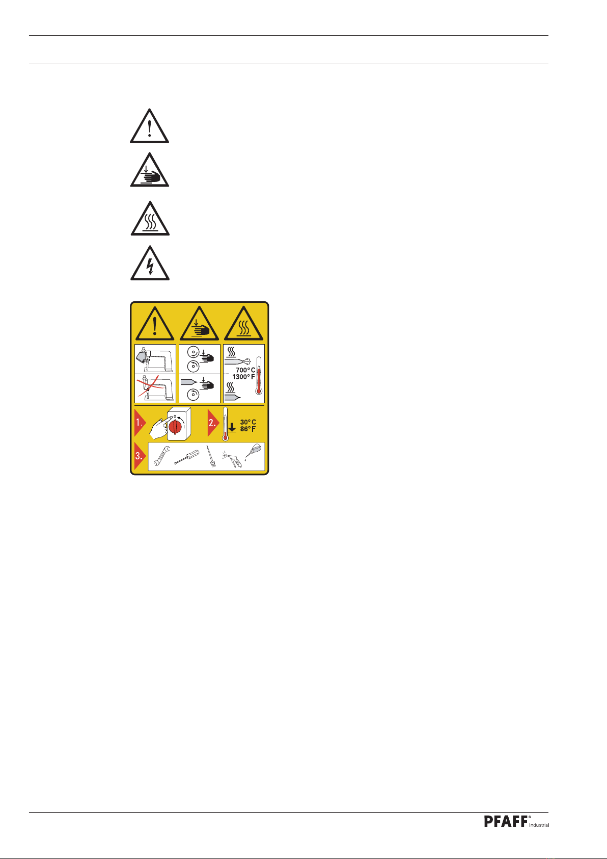
1.03 Safety symbols
Hazard point!
Special points of attention
Danger of hands being crushed!
Danger of burns from hot surface!
Fatal danger from electric voltage.
Caution!
Do not operate without finger guard and safety covers!
Turn off the main switch and let the machine cool
down before any set-up, maintenance and cleaning
work!
1.04 Special points of attention for the owner-operator
●This instruction manual is a part of the machine and must be made available to the
operating personnel at all times.
●The instruction manual must have been read before the initial start-up.
●The operating personnel and technical staff must be instructed about the machine's
safety covers and about safe working methods.
●The owner-operator may only operate the machine in a flawless condition.
●The owner-operator must ensure that no safety covers are removed or disabled.
●The owner-operator must ensure that only authorised persons work on the machine.
●The owner-operator must make sure there is no high-frequency sealing equipment be-
ing operated in direct proximity to the machine that exceeds the EMC limit values for the
machine according to EN 60204-31.
Additional information can be requested from the responsible sales centre.

Safety
7
1.05 Operating personnel and technical staff
1.05.01 Operating personnel
Operating personnel are persons responsible for setting up, operating and cleaning the ma-
chine and for clearing faults in the sealing section.
The operating personnel are obligated to comply with the following points:
●The safety instructions provided in the instruction manual must be followed for all work!
●Any work method jeopardising machine safety must be refrained from!
●Tight-fitting clothing must be worn. The wearing of jewellery such as chains and rings is
prohibited!
●Care must be taken to ensure that no unauthorised persons are located in the machine's
hazard zone!
●Any changes occurring on the machine which impair its safety must be reported to the
owner-operator immediately!
1.05.02 Technical staff
Technical staff are persons with technical training in electricity/electronics and mechanics.
They are responsible for lubricating, servicing, repairing and adjusting the machine.
The technical staff are obligated to comply with the following points:
●The safety instructions provided in the instruction manual must be followed for all work!
●Turn off the main switch and secure it against reactivation before starting any adjustment
and repair work!
●Never work on live parts and equipment! Exceptions are regulated by the EN 50110
standards.
●Reattach the safety covers following repair and maintenance work!
Safety
8
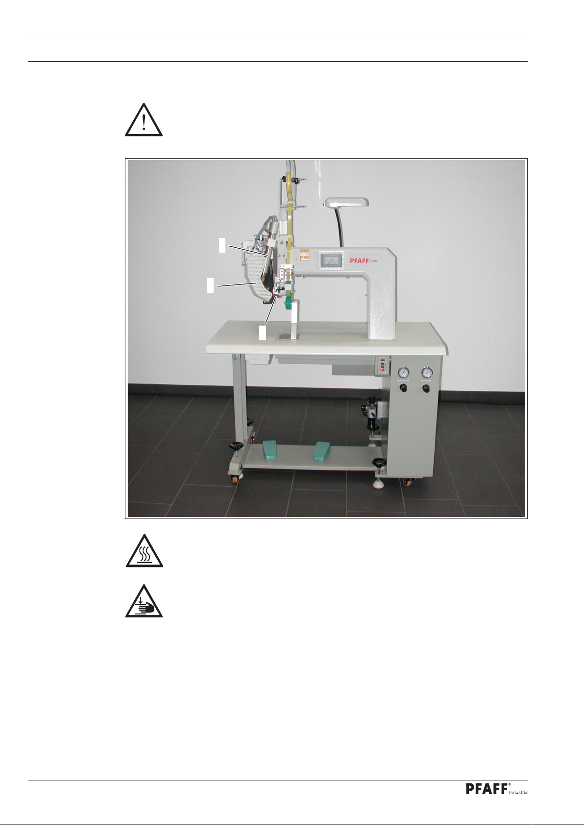
Fig. 1 - 01
1.06 Danger warnings
A work area of 1 m must be kept free in front of and behind the machine to
ensure unobstructed access at all times.
Do not operate the machine without the protective cover 1! Risk of burns when
touching the heating element 2!
Do not reach into the swivel range of the heating element 2and the swivel unit
3! Danger of crushing when engaging and disengaging the heating element!
1
2
3

Proper Use
9
2 Proper Use
The PFAFF 8306 is a hot air sealing machine with post.
The machine is used to heat-seal seams on water-repellent and breathable membrane
sheeting of all types, using a heat-sealing tape.
Any usage not approved by the manufacturer is deemed misuse! The manufac-
turer shall assume no liability for damage caused by misuse! Proper use also
includes compliance with the operating, maintenance, adjustment and repair
measures specified by the manufacturer!

Technical Data
10
3 Technical Datas
Dimensions and weights
Length:...........................................................................................................approx. 1350 mm
Width: ..............................................................................................................approx. 550 mm
Height (without tape reel bracket): ................................................................approx. 1780 mm
Passage width: ................................................................................................ approx. 420 mm
Passage between the rollers: ............................................................................approx. 20 mm
Working air pressure:............................................................................. min. 5.5 - max. 6.0 bar
Air consumption:.................................................................................................. 60 - 120 l/min
Sealing speed: ................................................................................................... max. 25 m/min
Sealing temperature: ................................................................................................. 0 - 700 °C
Connection data
Mains voltage (set for): ......................................................... 230 V ± 10 %, 50/60 Hz, 1 phase
Power consumption:.........................................................................................approx. 3600 W
Leakage current: .......................................................................................................... < 5 mAu
Noise data
Noise emission level at workplace: .................................................................. LpA < 70 dB(A)n
(Noise measurement in accordance with
DIN 45 635-48-A-1, ISO 11204, ISO 3744, ISO 4871)
Ambient temperature85% rel. humidity (condensation not permitted)....................... 5 - 40 °C
Net weight: ........................................................................................................ approx. 145 kg
sSubject to alterations
nKpA = 2.5 dB
uDue to the use of network filters there is a nominal leakage current of < 5mA
Table of contents
Popular Welding System manuals by other brands


Hobart Welding Products
Hobart Welding Products AirForce 375 owner's manual

GF
GF MSA 330 instruction manual

Hakko Electronics
Hakko Electronics FX-888D instruction manual

Abicor Binzel
Abicor Binzel ABIPLAS WELD 100 W operating instructions

EWM
EWM Taurus 355 Basic TDM operating instructions

Thermal Dynamics
Thermal Dynamics PakMaster 100 XL plus operating manual


