Philips AZ 3038 User manual

CD Sound Machine AZ 3038
all versions
Handling Chip Components and Safety ..........................1 - 1
Technical Specification & Measurement Setup ...............2 - 1
Service tools ....................................................................2 - 1
Service Measurement......................................................2 - 2
Connections and controls........................................3 - 1 3 -2
Instructions for use ..................................................3 - 3 3 -4
Block Diagram .................................................................4 - 1
Wiring Diagram................................................................4 - 2
Pins description and Block diagram of IC...............5 - 1 5 - 2
CD Board
circuit diagram .........................................................6 - 1
layout diagram................................................6 - 2 6 - 3
Tuner Board
circuit diagram .........................................................7 - 1
layout diagram.........................................................7 - 2
Tuner adjustment ....................................................7 - 2
Front Board
circuit diagram .........................................................8 - 1
layout diagram.........................................................8 - 2
Power Board
circuit diagram .........................................................9 - 1
layout diagram.........................................................9 - 2
Exploded view ...............................................................10 - 1
Mechanical partslist .......................................................10 - 2
Electrical partslist ...............................................11 - 1 11 - 2
©3140 785 32040
Published by YT 0313 Service Audio Printed in The Netherlands Subject to modification
CLASS 1
LASER PRODUCT
TABLE OF CONTENTS
©Copyright 2001 Philips Consumer Electronics B.V. Eindhoven, The Netherlands
All rights reserved. No part of this publication may be reproduced, stored in a retrieval
system or transmitted, in any form or by any means, electronic, mechanical, photocopying,
or otherwise without the prior permission of Philips.

HANDLING CHIP COMPONENTS
© WARNING
All ICs and many other semiconductors are susceptible to
electrostatic discharges (ESD). Careless handling during
repair can reduce life drastically.
When repairing, make sure that you are connected with the
same potential as the mass of the set via a wristband with
resistance. Keep components and tools at this potential.
f ATTENTION
Tous les IC et beaucoup d´autres semi-conducteurs sont
sensibles aux décharges statiques (ESD). Leur longévite
pourrait être considérablement écourtée par le fait qu´aucune
précaution nést prise à leur manipulation.
Lors de réparations, s´assurer de bien être relié au même
potentiel que la masse de l´appareil et enfileer le bracelet
serti d´une résistance de sécurité.
Veiller à ce que les composants ainsi que les outils que l´on
utilise soient également à ce potentiel.
d WARNUNG
Alle ICs und viele andere Halbleiter sind empfindlich
gegenüber elektrostatischen Entladungen (ESD).
Unsorgfältige Behandlung im Reparaturfall kann die
Lebensdauer drastisch reduzieren.
Sorgen Sie dafür, daß Sie im Reparaturfall über ein Puls-
armband mit Widerstand mit dem Massepotential des
Gerätes verbunden sind.
Halten Sie Bauteile und Hilfsmittel ebenfalls auf diesem
Potential.
ñ WAARSCHUWING
Alle IC´s en vele andere halfgeleiders zijn gevoelig voor
electrostatische ontladingen (ESD).
Onzorgvuldig behandelen tijdens reparatie kan de levensduur
drastisch doen vermindern. Zorg ervoor dat u tijdens reparatie
via een polsband met weerstand verbonden bent met hetzelfde
potentiaal als de massa van het apparaat.
Houd componenten en hulpmiddelen ook op ditzelfde potentiaal.
i AVVERTIMENTO
Tutti IC e parecchi semi-conduttori sono sensibili alle scariche
statiche (ESD).
La loro longevità potrebbe essere fortemente ridatta in caso di
non osservazione della più grande cauzione alla loro
manipolazione. Durante le riparationi occorre quindi essere
collegato allo stesso potenziale che quello della massa
delápparecchio tramite un braccialetto a resistenza.
Assicurarsi che i componenti e anche gli utensili con quali si
lavora siano anche a questo potenziale.
©
Safety regulations require that the set be restored to its
original condition and that parts which are identical with
those specified be used.
Safety components are marked by the symbol
i
Le norme di sicurezza estigono che l´apparecchio venga
rimesso nelle condizioni originali e che siano utilizzati i
pezzi di ricambiago identici a quelli specificati.
Componenty di sicurezza sono marcati con
ñ
Veiligheidsbepalingen vereisen, dat het apparaat in zijn
oorspronkeliijke toestand wordt teruggebracht en dat
onderdelen, identiek aan de gespecificeerde, worden toegepast.
De Veiligheidsonderdelen zijn aangeduid met het symbool
sVarning !
Osynlig laserstrålning när apparaten är öppnad och
spärren är urkopplad. Betrakta ej strålen.
∂Advarsel !
Usynlig laserstråling ved åbning når sikkerhedsafbrydere
er ude af funktion. Undgå udsaettelse for stråling.
ßVaroitus !
Avatussa laitteessa ja suojalukituksen ohitettaessa olet alttiina
näkymättömälle laserisäteilylle. Älä katso säteeseen !
f
"Pour votre sécurite, ces documents doivent être utilisés par
des spécialistes agréés, seuls habilités à réparer votre
appareil en panne".
ESD
SAFETY
d
Bei jeder Reparatur sind die geltenden Sicherheitsvor-
schriften zu beachten. Der Originalzustand des Gerätes
darf nicht verändert werden. Für Reparaturen sind Original-
ersatzteile zu verwenden.
Sicherheitsbauteile sind durch das Symbol markiert.
f
Les normes de sécurité exigent que l`appareil soit remis
à l`état d`origine et que soient utilisées les pièces de
rechange identiques à celles spécifiées.
Les composants de sécurité sont marqués
CLASS 1
LASER PRODUCT
©
DANGER: Invisible laser radiation when open.
©
After servicing and before returning the set to customer
perform a leakage current measurement test from all
exposed metal parts to earth ground, to assure no
shock hazard exists.
The leakage current must not exceed 0.5mA.
AVOID DIRECT EXPOSURE TO BEAM.
1 - 1

Mains voltage -/00C : 230 V
/05 : 240V
Mains frequency -/00C/05 : 50 Hz
Battery main set : 9 V (R14 x 6)
Power consumption : < 20 W (max.)
Dimension (W x H x D) : 294 x 145 x 245 mm
Weight : 2.4 Kg
Output power mains : 2 x 1 W
battery : 2 x 1 W
Speaker impedance : 2 x 8 ohm
Frequency response : 100 Hz - 10 kHz (±3dB)
Frequency response : 100 Hz - 10 kHz ±2dB
S/N ratio : 60 dB
Channel difference 1 kHz : 2 dB
Channel crosstalk 1 kHz : 40 dB
Laser wavelength : 780 ±20 nm
Laser light power : < 0.5 mW
Tuning range : 87.5 - 108 MHz
IF frequency : 10.7 MHz ±0.2 MHz
Sensitivity : 20 dBf at 26dB S/N
Selectivity : 30 dB at 300kHz
IF rejection : 50 dB
Image rejection : 20 dB
Crosstalk : 20 dB
Tuning range MW : 531 - 1602 kHz
IF frequency : 450 kHz ±1 kHz
Sensitivity MW : 4500 µV/m at 26dB S/N
Selectivity MW : 16 dB
IF rejection MW : 60 dB
Image rejection MW : 28 dB
TECHMICAL SPECIFICATIONS
GENERAL
AMPLIFIER
COMPACT DISC
TUNER - FM SECTION
TUMER - AM SECTION
2 - 1
SERVICE TOOLS
Audio signal disc SBC 429.......................................................................4822 397 30184
Playability test disc SBC 444...................................................................4822 397 30245
Test disc 5 (disc without errors ) +
Test disc 5A (disc with dropout errors, black spots and fingerprints)
SBC 426/426A.....................................................................4822 397 30096
Burn in test disc (65 min. 1kHz signal at -30 dB level without “pause”).....4822 397 30155
anti-static table mat large 1200x650x1.25mm 4822 466 10953
small 600x650x1.25m 4822 466 10958
anti-static wristband 4822 395 10223
connection box (3 press stud connections, 1MΩ) 4822 320 11307
extendible cable (2m, 2MΩ, to connect wristband to connection box) 4822 320 11305
connecting cable (3m, 2MΩ, to connect table mat to connection box) 4822 320 11306
earth cable (1MΩ, to connect any product to mat or to connection box) 4822 320 11308
KIT ESD3 (combining all 6 prior products - small table mat) 4822 310 10671
wristband tester 4822 344 13999
AVAILABLE ESD PROTECTION EQUIPMENT

2 - 2
SERVICE MEASUREMENT
Bandpass
250Hz-15kHz
e.g. 7122 707 48001
LF Voltmeter
e.g. PM2534
DUT
RF Generator
e.g. PM5326
S/N and distortion meter
e.g. Sound Technology ST1700B
Tuner SW
To avoid atmospheric interference all AM-measurements have to be carried out in a Faraday«s cage.
Use a bandpass filter (or at least a high pass filter with 250Hz) to eliminate hum (50Hz, 100Hz).
Ri=50Ω
Aerial replacement
Capacitor
R=50Ω
Bandpass
250Hz-15kHz
e.g. 7122 707 48001
LF Voltmeter
e.g. PM2534
DUT
S/N and distortion meter
e.g. Sound Technology ST1700B
Frame aerial
e.g. 7122 707 89001
Tuner AM (MW,LW)
To avoid atmospheric interference all AM-measurements have to be carried out in a Faraday«s cage.
RF Generator
e.g. PM5326
Ri=50Ω
Low pass filter 22kHz
L
R
LEVEL METER
e.g. Sennheiser UPM550
with FF-filter
S/N and distortion meter
e.g. Sound Technology ST1700B
DUT
CD
Use Audio Signal Disc SBC429 4822 397 30184 (replaces test disc 3)
L.P.F. = 13 th order filter 4822 395 30204

6 x 1.5 V R14 /UM2 / C CELL
2 x AAA/R03/UM4
32
1
2
3
7
8
4
5
6
#
$
%
9
0
!
0
@
1
2
3
1
3 - 1
CONNECTIONS AND CONTROLS
45 6
78 9
0!@
#
X
$

3 - 2
English
CONTROLS POWER SUPPLY
Using AC Power
1Check if the power voltage, as shown on the type
plate located on the bottom of the set, corresponds
to your local power supply. If it does not, consult
your dealer or service centre.
2Connect the power cord to the AC MAINS inlet and
the wall outlet. The power supply is now
connected and ready for use.
3To switch off completely, unplug the power cord
from the wall outlet.
•Unplug the power cord from the wall outlet to
protect your set during heavy thunderstorms.
The typeplate is located on the bottom of the set.
Switching power on/off: Save energy
Whether you are using mains or battery supply, to
avoid unnecessary energy consumption always adjust
the source selector to off.
General operation
1To select your sound source adjust the source
selector to CD/TUNER/OFF.
2Adjust the sound with the VOLUME and DBB
(Dynamic Bass Boost) controls.
3To switch off the set, adjust the source selector to
off position.
Note: When the set is switched off the tuner presets
will be retained in the set’s memory.
Radio reception
1Adjust the source selector to TUNER.
™Display: shows briefly.
2Press FM•MW once or more to select the desired
waveband.
™Display: shows your waveband and the preset
number and the frequency of a preset station if
already programmed (See 4).
3Press and hold down or §
§
§
briefly to tune to a
radio station. Release when the frequency in the
display starts to change.
™The radio automatically tunes to a radio station
of sufficient reception. Display shows
during automatic tuning.
–
If you want to stop automatic tuning,
press or §briefly.
– For FM, pull out the telescopic aerial. Incline and
turn the aerial. Reduce its length if the signal is too
strong (very close to a transmitter).
– For MW (AM) the set is provided with a built-in
aerial so the telescopic aerial is not needed. Direct
the aerial by turning the whole set.
Programming radio stations
You can store up to a total of 32 radio stations in the
memory.
1Tune to your desired station (see Radio Reception).
2Press PROG•MODE to activate programming.
™Display: flashes.
3Press PRESET•TRACK –, +10 once or more to
allocate a number from 1 to 32 to this station.
4Press PROG•MODE again to confirm the setting.
™Display: disappears, the preset number
and the frequency of the preset station are
shown.
5Repeat steps 1-4 to store other stations.
•You can erase a preset station by storing another
frequency in its place.
Top and front panels (See 1)
1VOLUME
– adjusts volume level
2DBB (Dynamic Bass Boost)
– enhances bass response
3Source selector
– selects source of sound CD or TUNER. Also the
power off switch
4PRESS TO PLAY 2;
– starts or pauses MP3-CD/ CD playback
5STOP 9
– stops MP3-CD/ CD playback; erases a MP3-CD/
CD programme
6LIFT TO OPEN
– opens/ closes the CD door
7Display
– shows the CD player and tuner functions
8PROG•MODE
MP3-CD: – programmes and reviews programmed
track numbers;
– plays tracks MP3-CD/ CD/ programme
in random order;
– repeats a track/ MP3-CD/CD /
programme
Tuner: – programmes tuner preset stations
9FM•MW
– selects FM/ MW (AM) waveband
0PRESET•TRACK –, +10
MP3-CD: fast skips to the next/ previous
10 MP3-CD tracks
Tuner: selects a preset station (down, up)
!SEARCH ,§
§
MP3-CD: skips or searches a passage/track
backwards or forward
Tuner: tunes to a station (up, down)
@IR sensor
– infrared for remote control
Back Panel (See 1)
#Telescopic aerial
– to improve FM reception
$Battery door
– to open battery compartment
%AC MAINS
– inlet for mains lead
Remote Control
1¡,™ – skips to the next/ previous track
22; – to start or interrupt MP3-CD/CD playback
39– to stop playback; to erase a programme
Power Supply
Whenever convenient, use the power supply if you
want to conserve battery life. Make sure you remove
the plug from the set and wall outlet before inserting
batteries.
For users in the U.K.: please follow the instructions in
the box, Important notes for users in the U.K.
Batteries (not included) (see 2)
Open the battery compartment and insert six
batteries, type R-14, UM-2 or C-cells, (preferably
alkaline) with the correct polarity as indicated by the
"+" and "–" symbols inside the compartment.
Remote control (see 3)
Insert 2 batteries, type AAA, R03 or UM4 (preferably
alkaline).
Batteries contain chemical substances, so they
should be disposed of properly.
Incorrect use of batteries can cause electrolyte
leakage and will corrode the compartment or cause
the batteries to burst. Therefore:
• Do not mix battery types: e.g. alkaline with carbon
zinc. Only use batteries of the same type for the
set.
• When inserting new batteries, do not try to mix old
batteries with the new ones.
• Remove the batteries if the set is not to be used
for a long time.
GENERAL OPERATION DIGITAL TUNER
CONNECTIONS AND CONTROLS

3 - 3
Autostore
Autostore automatically starts programming radio
stations from preset 1. Available stations are
programmed in order of waveband reception strength:
FM, followed by MW (LW). Any previous presets e.g.
manually programmed will be erased.
• Press PROG•MODE for 5 seconds or more to
activate autostore programming. (If you want to
stop autostore programming, press PROG•MODE
briefly again.)
The display shows , prog blinks, followed
by the radio station details when stored (See 5).
After all stations are stored, the first preset
station will then automatically play.
MP3-CD/CD Player
General information
Supported formats:
–Disc format: ISO 9960, Joliet, finalized
multisession
–MP3 music files
–MP3 bit rate (data rate): 32-320 kbps and variable
bit rate
–Total number of music files maximum: 999
–Some encoder software offer an option to protect
music files, i.e. the files can only be played on the
computer which created them. If you burn such
files on a CD-ROM, you cannot play them on this
unit. Make sure to deactivate the protection option
in the encoder software before creating the music
files. In this case you are responsible for adherence
to all local or international copyrights.
MP3-CD
• Make sure the file names of the MP3 files end
with .mp3
This set does not play/ support the following:
–UDF disc format.
–Non-finalized discs.
–Recordings created on e.g. DirectCD, Packet
Writing and Package Writing.
–Playlist files e.g. m3u, pls of WMA, AAC, Winamp,
Sonic, RealJukebox, MS Mediaplayer 7.0,
MusicMatch.
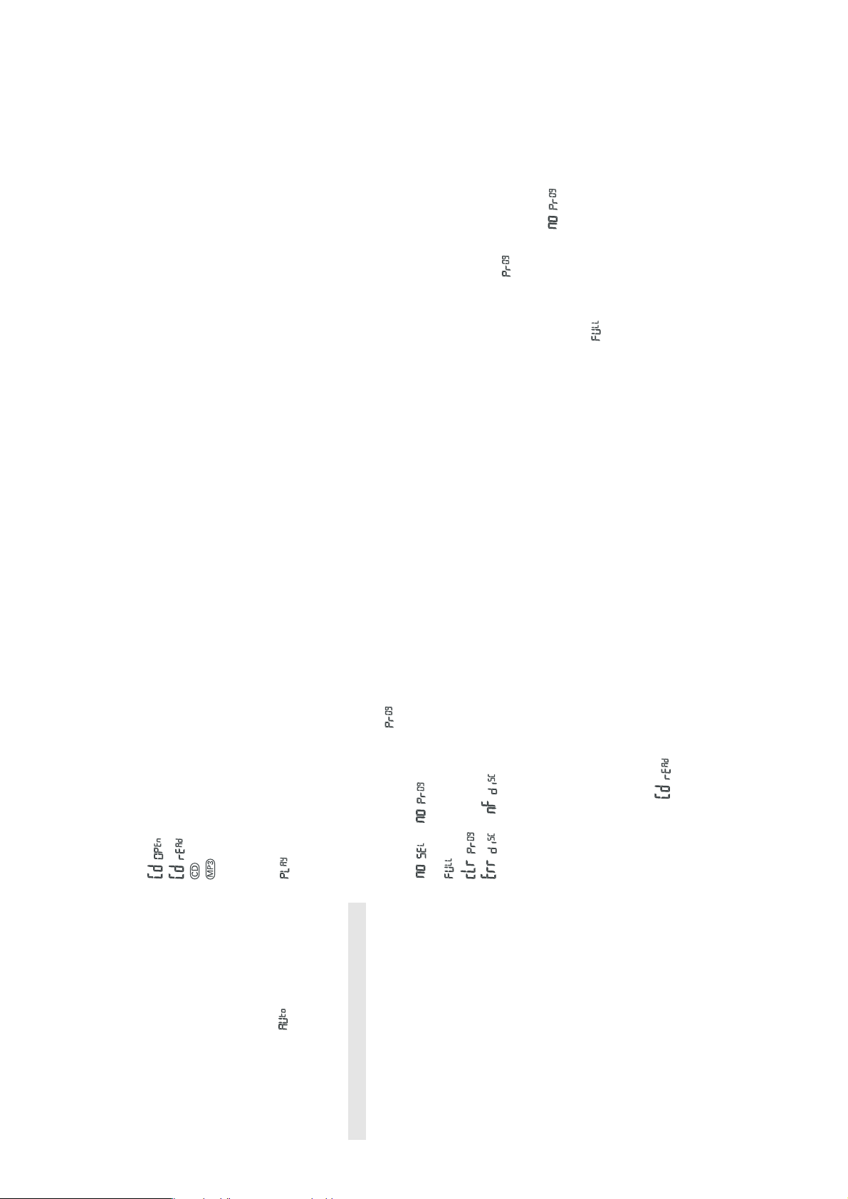
Display indication for CD functions
–:CD door open
–:when reading disc contents (See 6)
–:icon throughout CD operation
–:icon throughout MP3-CD operation
– In stop mode: total track number and total
playback time (CDs); or total album and track
number for MP3-CD and mixed format CDs
(See 7)
–:and the current track number at the
beginning of a track (See 8)
– During CD playback: elapsed playback time of
current track and current track number
–Pause: elapsed playback time flashes (See 9)
–Shuffle/ repeat modes: when the respective mode
is activated
–prog when CD programme active; also
appears briefly when you store a track (See 0).
–or : programme activated but
no tracks selected (See !).
–:programme memory full
–:programme cancelled (See @)
–or : no disc/ error in CD
operation/ CD-R(W) is blank or the disc is not
finalized (see Troubleshooting).
MP3-CD/ CD playback
This unit can play:
–all pre-recorded audio CDs
–all finalized audio CDR(W)s
–MP3-CDs (CD-ROMs with MP3 files)
1Adjust the source selector to CD.
Display: shows briefly (See 6).
Note: MP3-CDs may take more than 10 seconds to read.
2To open the CD door, lift the CD door at the edge
marked LIFT TO OPEN.
3Insert a disc with the printed side facing up and
press the CD door gently close.
4Press 2; on the set to start playback.
5To pause playback press2;. To resume, press 2;
again.
6To stop CD playback, press STOP 9.
Note: CD play will also stop when:
–you open the CD compartment;
–you select TUNER source;
–the CD has reached to the end.
Selecting a different track
During playback you can use the buttons ¡or ™(or in
MP3-CD, press PRESET•TRACK –, +10) to select a
particular track.
–
If you have selected a track number in the stop or
pause position, press 2; to start playback.
• Press ™once briefly for the next track, or press
repeatedly until the desired track number appears
in the display.
• Press ¡once briefly to return to the beginning of a
current track.
• Press ¡more than once briefly for a previous
track.
• Press PRESET•TRACK –, +10 once or more to fast
skip to the previous/ next 10 tracks.
Finding a passage within a track
1Press and hold down ∞or §.
•The CD is played at high speed.
2When you recognize the passage you want release
or .
™Normal playback resumes.
Note: During playback of a CD, MP3-CD, programme
or when SHUFFLE/REPEAT is active, searching is
only possible within a track.
Different play modes: Shuffle and Repeat
PROG•MODE allows you to select various play
modes. The modes can be selected or changed during
playback of an entire CD/ CD programme in the
following sequence:
shuffle – all tracks are played in random order
shuffle repeat all – repeats the entire disc in
random order
repeat all – plays the whole disc continuously
repeat – plays the current track continuously
1During playback, select your play mode by pressing
PROG•MODE once or more until the desired play
mode is shown.
Display: your selected mode flashes 2 seconds
before playback
•You can use ¡or ™(or in MP3-CD, press
PRESET•TRACK –, +10) to skip tracks during the
shuffle/ repeat modes.
•The shuffle/ repeat play options can be combined
and used with a programme: e.g. shuffle/ repeat all
repeats the entire disc/ programme in random
order.
2To return to normal playback press PROG•MODE
until the shuffle/ repeat modes are no longer
shown.
•You can also press 9to quit the play mode.
Programming track numbers
You may store up to 20 tracks in the desired
sequence. If you like, store any track more than once.
1In the STOP mode, press ¡or ™(or in MP3-CD,
press PRESET•TRACK –, +10) for your desired
track.
2When your chosen track number appears, press
PROG•MODE once to store the track.
Display shows , your selected track
number, and the accumulated programming time.
If you attempt to programme without first
selecting a track number, is shown.
3Repeat steps 1 to 2 to select and store all desired
tracks in this way.
is displayed if you attempt to programme
more than 20 tracks.
4To play your programme, press2; .
Reviewing your set programme
•In the STOP mode, press and hold down
PROG•MODE for more than one second.
Display shows all your stored track numbers in
sequence.
DIGITAL TUNER MP3-CD/ CD PLAYER MP3-CD/ CD PLAYER
∞§
INSTRUCTIONS FOR USE

3 - 4
Erasing a programme
You can erase the contents of the memory by:
– opening the CD door;
– selecting TUNER source;
– pressing 9(twice during playback or in the stop
position).
Display: shows briefly when
programme is cancelled. (See @)
Precautions & General Maintenance (See #)
•Place the set on a hard and flat surface so that the
system does not tilt.
•Do not expose the set, batteries or CDs to
humidity, rain, sand or excessive heat caused by
heating equipment or direct sunlight.
•Do not cover the set. Adequate ventilation with a
minimum gap of 6 inches between the ventilation
holes and surrounding surfaces is necessary to
prevent heat build-up.
•The mechanical parts of the set contain self-
lubricating bearings and must not be oiled or
lubricated.
•To clean the set, use a soft dry cloth. Do not use
any cleaning agents containing alcohol, ammonia,
benzene or abrasives as these may harm the
housing.
CD player and CD handling (See $)
•The lens of the CD player should never be touched!
•Sudden changes in the surrounding temperature
can cause condensation to form and the lens of
your CD player to cloud over. Playing a CD is then
not possible. Do not attempt to clean the lens but
leave the set in a warm environment until the
moisture evaporates.
•Always close the CD door to keep the CD
compartment dust-free. To clean, dust the
compartment with a soft dry cloth.
•To clean the CD, wipe in a straight line from the
centre towards the edge using a soft, lint-free
cloth. Do not use cleaning agents as they may
damage the disc.
•Never write on a CD or attach any stickers to it.
– Problem
• Solution
No sound /power
–Volume not adjusted
•Adjust the VOLUME
–Power cord not securely connected
•Connect the AC power cord properly
–Batteries dead/ incorrectly inserted
•Insert (fresh) batteries correctly
Display does not function does not function
properly/ No reaction to operation of any of
the controls
–Electrostatic discharge
•Switch off and unplug the set. Reconnect after a
few seconds
or indication
MP3-CD/ CD playback does not work
–No disc inserted
•Insert a disc
–Disc badly scratched or dirty
•Replace/ clean disc (see Maintenance)
–Laser lens steamed up
•Wait until lens has recovered to room temperature
–CD-R(W) is blank or the disc is not finalized
•Use a finalized CD-R(W)
–Incompatible format used for MP3
•Check if your disc format is ISO 9960, Joliet,
finalized multisession
–Not all known encrypted and protected CDs are
compatible
•Make sure to deactivate the protection option in the
encoder software before creating the music files
The disc skips tracks
–Disc damaged or dirty
•Replace or clean disc
–Shuffle or a programme is active
•Quit shuffle/ programme mode(s)
Sound skips during MP3 playback
–MP3 file made at compression level exceeding
320kbps
•Use a lower compression level to record CD tracks
into MP3 format
Cannot find desired MP3 title
–Wrong file extension/ used
•Change file extension to .MP3
Troubleshooting
If a fault occurs, first check the points listed below before taking the set for repair.
Do not open the set as there is a risk of electric shock.
If you are unable to remedy a problem by following these hints, consult your dealer or service centre.
WARNING: Under no circumstances should you try to repair the set yourself, as this will invalidate the
guarantee.
MP3-CD/ CD PLAYER MAINTENANCE TROUBLESHOOTING
Environmental information
All unnecessary packing material has been omitted. The packing can be easily separated into three materials:
cardboard, polystyrene and plastic.
Your set consists of materials which can be recycled if disassembled by a specialized company. Please observe
the local regulations regarding the disposal of packing materials, dead batteries and old equipment.
For more detail on operation instruction please visit Philips Audio internet site :
http://www.audio.philips.com
INSTRUCTIONS FOR USE

4 - 14 - 1
BLOCK DIAGRAM

4 - 2 4 - 2
WIRING DIAGRAM

5 - 15 - 1
BLOCK DIAGRAM
Input/Output
Buffers
X-Decoder
Y-Decoder
Chip Enable
Output Enable
Logic
Erase Voltage
Generator
PGM Voltage
Generator
Timer
VCC Detector
State
Control
Command
Register
VCC
VSS
WE#
BYTE#
CE#
OE#
STB
STB
DQ0
–
DQ15 (A-1)
Sector Switches
RY/BY#
RESET#
Data
Latch
Y-Gating
Cell Matrix
Address Latch
A0–A17
so
44 RESET#
43 WE#
42 A8
41 A9
40 A10
39 A11
38 A12
37 A13
36 A14
35 A15
34 A16
33 BYTE
32 Vss
31 DQ15/A-1
30 DQ7
29 DQ14
28 DQ6
27 DQ13
26 DQ5
25 DQ12
24 DQ4
23 Vcc
MC 1
RY/BY# 2
A17 3
A7 4
A6 5
A5 6
A4 7
A3 8
A2 9
A1 10
A0 11
CE# 12
Vss 13
OE# 14
DQ0 15
DQ8 16
DQ1 17
DQ9 18
DQ2 19
DQ10 20
DQ3 21
DQ11 22
PINS DESCRIPTION OF IC
29ILV400B BLOCK DIAGRAM OF IC
BA6892FP

5 - 2 5 - 2
SPI
Interface
I2S
Interface
Clock
Oscillator
RDS
Decoder
and
ARROW
Interface
CD
Controller
and
ARROW
Interface
GPIO A
(eg. LCD or
VFD interface,
CD mechanism
and multi-
chan
g
er
)
AC97
Interface
IR
Receiver
GPIO B
(switch matrix
driver / position
encoder)
GPIO C
(twin logic cassette
deck control, radio
tuner, ARROW
control, and NVR
control
)
GPIO D (dual function)
GPIO/Data
GPIO/External Interrupt
GPIO/Stereo DAC
GPIO/Power-On-Config
DSP
UART
Debug
Port
Interrupt
Controller
and
Priority
Logic
Round /
Normaliser
Shifter
External
Memory
Controller
and
Arbitrator
Support Unit 1
for CD Error
Correction
ALU
MACC
Register
File
R0 to R7
RAM B
Stack Pointer
Fla
g
s
Program
Counter
OpCode
Decode
and
Execution
State
Machine
RAM A Program
RAM
Control
Re
g
isters
Address
Generator
and
Arbitrator
Support Unit 2
for CD Error
Correction
DART
Pin Name I/O
Function
2-9 XD15-8 I/O
Data Bus bit 15-8 /
GPIO D bit 15-8
11-18 XD7-0 I/O
Data Bus bit 7-0
19-43 A0-18 O
Address Bus bit 0
-18
44 WEL0 O Memory Write Enable
45 WEL1 O Memory Write Enable
46 OEL O Memory Output Enable
47 SCSL O SRAM Chip Select
48 RASL O DRAM Row Address Strobe
49 UCASL O DRAM Column Address Strobe
50 LCASL O DRAM Column Address Strobe
51 BCSL O BootROM Chip Select
53-58 GPIO0-5 I/O
GPIO A bit 0-5
60 XTLIN I External Crystal
61 XTLOUT O External Crystal
63-73 GPIO6-15 I/O
GPIO A bit 6-15
75-85 GPIO16-23
I/O
GPIO B bit 0-7
86-93 GPIO24-31
I/O
GPIO B bit 8-15
95-112
GPIO32-47
I/O
GPIO C bit 0-15
113 GPIO48 I/O
GPIO D bit 0
116 GPIO49 I/O
GPIO D bit 1 / Left DAC
117 GPIO50 I/O
GPIO D bit 2 / Right DAC
118 GPIO51 I/O
GPIO D / External Interrupt
119 GPIO52 I/O
GPIO D / BootROM Width
123 GPIO53 I/O
GPIO D / Clock Divide Ratio
124 GPIO54 I/O
GPIO D / Clock Divide Ratio
125 GPIO55 I/O
GPIO D / Clock Divide Ratio
126 RFIN I CD Raw Data
127 FE_IN I CD Focus Error
128 RE_IN I CD Radial Error
129 CA_IN I CD Central Aperture
130 FOCUS O CD Focus
131 TRACK O CD Tracking
132 SPINDLE O CD Spindle
133 SLED O CD Sled
134 REF O CD DAC Reference
135 MPX_IN I RDS Bitstream Data
136 LASER O CD Laser Enable
138 ADC_CLK
O 11MHz Sigma Delta Clock
140 SCLK O SPI Clock
141 MOSI O SPI Data Out
142 MISO I SPI Data In
143 ERESETL
I Reset
144 AC97CLK O 22MHz Clock
145 SYNC O Sync Pulse
146 SDOUT O Serial Data Out
147 BITCLK I 11 MHz Bit Clock
148 SDATAIN I Serial Data In
150 RXD I UART DATA In
151 TXD O UART DATA Out
152 I2SWS O I2S Word Select
153 I2SCLK O I2S Clock Out
154 I2SDATA O I2S Data Out
156 IRIN I Infra Red (IR) Detector
157 TEST0 I (No Connection)
158 TEST1 I (No Connection)
1, 20, 29, 40, 52, 74, 81, 100, 114, 120, 137, 149,
155
Vdd
10, 21, 41, 42, 59, 62, 65, 79, 80, 94, 101, 115,
121, 122, 139, 159, 160
Vss
BLOCK DIAGRAM
SERIAL
INTERFACE
DIGITAL
FILTERS
WM8725
1
LRCIN
DIN
BCKIN
NC
CAP
VOUTR
GND
SCKI
FORMAT
NC
DEEMPH
MUTE
VOUTL
VDD
14
213
12
11
10
9
8
3
4
5
6
7
DIGITAL
SIGMA-DELTA
MODULATOR
SWITCHED
CAPACITOR
DAC
DIGITAL
SIGMA-DELTA
MODULATOR
SWITCHED
CAPACITOR
DAC
FORMAT (13)
SCKI (14)
LRCIN (1)
DIN (2)
BCKIN (3)
(6) VOUTR
(9) VOUTL
(12)
DEEMPH (10)
MUTE (8)
VDD (5)
CAP (7)
GND
WM8725
BLOCK DIAGRAM AND PINS DESCRIPTION
GSL88301 PINS DESCRIPTION OF IC
WM8725

6 - 16 - 1
CD BOARD - CIRCUIT DIAGRAM

6 - 2 6 - 2
CD BOARD - LAYOUT DIAGRAM

6 - 36 - 3
CD BOARD - LAY0UT DIAGRAM

7- 1 7 - 1
TUNER BOARD - CIRCUIT DIAGRAM

7 - 27 - 2
VARICAP ALIGNMENT
FM RF
FM IF
VCO
AM IF
AM RF 3)
108MHz
87.5MHz
(65.81MHz)
87.5MHz
(65.81MHz)
87.5MHz
(65.81MHz)
279kHz
153kHz
1602kHz
531kHz
5130
check
5122
check
5123
check
8V ±0.2V
4.3V ±0.5V
(1.2V ±0.5V)
8V ±0.2V
1.1V ±0.4V
8V ±0.2V
1.1V ±0.4V
1494kHz
558kHz
560kHz
1500kHz
5105
LW ferrite coil
198kHz
1494kHz
558kHz
560kHz
1500kHz
198kHz
2106
5104
MW ferrite coil
5104
MW ferrite coil
2106
3142 152kHz ±1kHz 1)
98MHz
5112
MAX
FM
87.5 - 108MHz
(65.81 - 74, 87.5 - 108MHz)
LW
153 - 279kHz
MW
FM/MW/LW- version, 9kHz grid
531 - 1602kHz
1700kHz
530kHz 5123
check 8V ±0.2V
1.1V ±0.4V
1602kHz
531kHz 5123
check 6.9V ±0.2V
1.1V ±0.4V
108MHz 108MHz 2155
5131
MW
FM/AM-version, 10kHz grid
530 - 1700kHz
FM
MW
LW
98MHz, 1mV
continuous wave
450kHz
connect pin 6 of
IC 7101 (AM Osc.)
with 2.2kΩto Vcc
Use Service Testprogram. By selecting the TUNER TEST test frequencies will be stored as preset frequencies automatically.
4
1
3
5
5
A
A
5119FM 10.7MHz, 45mV
continuous wave 2D
mod=1kHz
∆f=±22.5kHz
1)
If sensitivity of frequency counter is too low adjust to max. channel separation
(input signal: stereo left 90% + 9%, adjust output on right channel to minimum)
Repeat
ECO6, general with ferrite antenna, 070799
TUNER ADJUSTMENT TABLE ( ECO6 FM/MW- and FM/MW/LW - versions with ferrite antenna)
∆f=±10kHz
VRF = 0.5mV
C
see
remark 2)
220R
100nF
36
IC 7101
220R
100nF
40
IC 7101
2141
shortcircuit
to block AFC
21
IC 7101
max.
symmetric
fo
AM AFC
MW C
continuous wave
VRF = 2mV
5111
5114 20 ±2 mV DC
0 ±3 mV DC
MW
FM/MW/LW- and FM/MW-version
( 9kHz grid)
531 - 1602kHz
B
∆f = ±30kHz
VRF as low as
possible
max.
symmetric
fo
MW
FM/AM-version, 10kHz grid
530 - 1700kHz
2)
RC network serves for damping the IF-filter while adjusting the other one.
3)
LW has to be aligned before MW.
Waverange Input frequency Input Tuned to Adjust Output Scope/Voltmeter
FM
87.5 - 108MHz
(65.81 - 74, 87.5 - 108MHz)
FM/MW-version, 9kHz grid
531 - 1602kHz
(as low as
possible)
These assembly drawings show a summary of all possible versions.
For components used in a specific version see schematic diagram respectively partslist.
ECO6 PA 34450 stage .2, 110700
41..
in schematic diagram)
(not all items shown
SMD jumper
EB
C
A
K
123434
125
black
black
red
red
LWMW
blue
5104 5105
2101 B3
2103 E3
2104 B3
2108 D2
2109 D1
2110 C1
2111 C2
2112 B4
2119 C1
2120 C1
2122 C2
2123 C2
2124 C2
2125 C1
2126 D5
2127 D5
2130 D5
2131 D5
2132 D5
2134 E6
2135 D6
2136 A3
2137 A3
2139 D5
2140 D6
2141 D6
2144 C6
2145 A4
2146 C6
2147 A4
2148 B6
2149 E6
2150 C4
2152 E4
2153 D4
2159 D4
2161 B5
2163 B6
2164 D6
2165 C4
2166 C6
2167 C6
2169 A2
2187 B7
2188 C7
2189 E7
2192 B7
2193 A7
2194 C7
2196 A6
2197 C7
3101 E4
3102 D2
3103 D4
3104 B3
3105 C3
3106 E2
3107 C1
3108 C1
3109 D2
3113 B5
3119 B5
3123 E5
3125 E6
3128 B2
3132 E4
3134 C2
3137 C3
3141 D4
3143 D7
3144 A3
3145 E5
3152 A4
3153 A4
3155 E6
3156 B5
3157 A5
3158 B3
3159 A4
3160 A4
3161 A4
3166 B6
3167 E7
3169 C6
3170 A5
3176 D5
3180 C3
3181 D4
3186 A6
3187 B7
3188 A6
3189 B7
3190 B6
3191 C7
3192 B7
3193 D7
3194 D7
3195 E7
3196 C7
4101 D1
4102 D1
4104 C2
4105 B4
4106 C3
4107 D4
4108 D3
4109 D2
4110 D1
6103 B2
6105 C2
6106 D2
6120 A5
6130 D4
6131 D3
6181 B7
6182 C7
6183 C7
7101 C5
7102 D3
7103 E6
7109 E5
7111 A5
7119 B5
7122 B2
7124 C2
7180 B7
7181 C7
7182 D7
7183 B7
TUNER BOARD ECO6 PA /
copperside view
4 3
D
1
A
C5
2
B
Vcc1
Vcc2
Vdd
ECO6 PA combi layout 34450 stage .2, 110700
1105 B7
1121 B6
1122 B5
2106 D6
2107 C6
2128 C4
2129 C5
2133 D3
2138 D2
2155 C5
2186 C1
2190 B1
2191 A2
2195 C1
3142 E1
5102 D7
5103 E7
5109 B4
5110 B3
5111 B4
5112 B3
5114 B3
5119 D2
5121 C2
5122 B6
5123 B7
5130 D4
5131 E5
7104 C7
7105 D6
9101 B2
9102 D2
9103 B1
9104 B7
9105 D1
9106 C4
9107 D5
9108 C5
9109 E2
9110 E2
9111 C2
9112 D6
9113 D6
9114 E6
9115 D7
TUNER BOARD ECO6 PA /
componentside view
AM-AFC
DISC.
VCO
LW MW
AM-IF2
AM-IF1
FM-IF1
FM-OSC.
LW-OSC. MW-OSC.
FM-RF
FM-RF AM-RF
LW-RF
MW-RF
FM-IF2
B
A
TUNER BOARD - LAYOUT DIAGRAM

8 - 1 8 - 1
FRONT BOARD - CIRCUIT DIAGRAM

8- 28 - 2
FRONT BOARD - LAYOUT DIAGRAM

9 - 19 - 1
POWER BOARD - CIRCUIT DIAGRAM
Table of contents
Other Philips CD Player manuals

Philips
Philips AZ300/55 User manual

Philips
Philips AZ216 User manual

Philips
Philips AZ1140/00 User manual

Philips
Philips AZ330T/96 User manual

Philips
Philips AZ1830 User manual

Philips
Philips AX2412 User manual

Philips
Philips EXP2540 User manual

Philips
Philips ACT 7585 User manual

Philips
Philips CD 605 User manual

Philips
Philips AX5301 User manual

Philips
Philips AZ 7275 User manual

Philips
Philips AX5301/00C User manual

Philips
Philips CDI350 User manual

Philips
Philips AZT9500 User manual

Philips
Philips AZ5738/93 User manual

Philips
Philips cd380 User manual

Philips
Philips AZ1560/17 User manual

Philips
Philips AZ 7462 User manual

Philips
Philips AZ1830/12 Operating manual

Philips
Philips AZ114D User manual