Philips LBB 6066 User manual

LBB 6063/.
5 digit numeric display
Alpha display (24 character)
Connector for external
mic/loudspeaker.
/00
/02 /04 /09
Function table LBB 6063, Generation III Talk-back transceiver
1. GENERAL
This installation instruction covers the following four paging
transceivers:
- LBB 6063/xx Gen. III Transceiver
- LBB 6064/xx Gen. III Transceiver with dial keypad
- LBB 6065/xx Gen. III PS 6000 transceiver
- LBB 6066/xx Gen. III PS 6000 transceiver with dial
keypad
The stroke numbers are used for different versions of the
transceivers. For an overview of the available functions refer to
Tables 1, 2 and 3.
On delivery the transceivers are without HF transmitter and
receiver section. These sections should be ordered separately
and are available with the following type numbers:
- LBB 6112/xx VHF receiver HF section
- LBB 6012/xx UHF receiver HF section
- LBB 6113/xx VHF talk-back transmitter HF section
- LBB 6013/xx UHF talk-back transmitter HF section
The main section of this installation instruction describes the
installation and programming of transceivers with dual display
(i.e numeric display located on top of the transceiver and an
alphanumeric display located on the side of the transceiver).
The installation and programming of the LBB 6063/02 (no dis-
play) and LBB 6063/04 (numeric display only) are described in a
separate section at the rear of this installation instruction.
INSTALLATION
INSTRUCTIONS
DP 6000 DIGITAL PAGING SYSTEM
February1997, Page 1 of 29
DP 6000 Generation III Transceivers
LBB 6063, LBB 6064, LBB 6065, LBB 6066
Philips
Communication &
Security Systems
83
LBB 6064/.
5 digit numeric display
Alpha display
Connector for external
mic/loudspeaker.
/00 /09
Function table LBB 6064,
Generation III Talk-back transceiver with dial key-pad
LBB 6065/.. & LBB 6066/..
Numeric + Alpha display
Manual - No move - Tilt -
Fast move - Alarms
Tear-off Alarm
Connector for external
mic/loudspeaker.
Location detection
/00 /06 /07 /08 /09* /10*
* Not deliverable as from 01-0-98
Function table LBB 6065, Generation III PS 6000 Transceiver and LBB 6066,
Generation III PS 6000 Transceiver with dial key-pad
TABLE 1
TABLE 2
TABLE 3

2. INTRODUCTION
For the operation of the transceiver refer to the ‘User Guide’
supplied with each transceiver. The following gives an overview
of a transceiver. The version illustrated is the LBB 6066/..
Personal security transceiver.
The paging transceiver has four main functions:
1. To alert the transceiver carrier when called with one of 14
different bleep patterns.
2. To display 5-digit numeric and 24 character alphanumeric
messages (display versions only).
3. To provide two-way verbal communication between cen-
tral control and other DP6000 transceiver carriers.
4. To provide personal security (LBB 6065/.. and LBB 6066/..
versions only)
KEY TO SYMBOLS (Fig. 1)
1. Antenna
2. Tear-out alarm. (includes chain attachment, /06,/07 and /08
only)
3. 5-digit numeric display
4. Status indication:
Red - Transmitting
Green - Receiving
5. Numeric message memory <Recall> and <Reset> button
6. Chain securing attachment
7. Connection cover for external unit (available with versions
LBB 6063/09, LBB 6064/09, LBB 6065/08 & /09 and
LBB 6066/08 & /09 only)
8. Scroll buttons (up/down to scroll menu options and
browse stored alphanumeric messages)
9 Menu button (activates transceiver options)
10. Label placement
11. Storage rack securing attachment
12. Charging contacts (for use in storage rack)
13. Battery compartment ( 3 x LR1)
14. Dial keypad (LBB 6064/xx & LBB 6066/xx only for direct
selection of call numbers)
15. <Light> button (press to switch on display back-light in low
light conditions). This button can be programmed to trans-
mit the second pilot tone (Opcode programming).
16. ‘Enter’ button (to select options from menu)
17. Alphanumeric LC display (to display incoming messages or
set-up menu)
18. <Press-to-talk> switch
19. <Alarm> key (LBB 6065 & LBB 6066 only)
Rear of transceiver (Fig.2)
18. <Press-to-talk> switch
20. Storage rack securing attachment
21. Microphone
22. Loudspeaker
23. Panel mounting screws (4 off)
DP 6000 DIGITAL PAGING SYSTEM INSTALLATION INSTRUCTION 83
February 1997 Page 2/29
DISPLAY SYMBOLS (display versions only)
When activated a display bar is displayed under the relevant
symbol.
(A) Low battery voltage indicator. (If programmed
accompanied by a bleep until reset)
(B) Out of Range indicator (if active in the system). No
calls can be received and a bleep signal emitted until
reset. After 32 minutes (out-of range status) the
transceiver switches off automatically
(C) Message locked indication (applicable also for pre-
programmed short calls)
(D) Bleep-on indication
(E) Bleep volume level indication (programmable loud or
soft)
(F) Transceiver in programming mode.
(G) Pilot tone indication (I or II)
(H) Alarm indication (indicates if one or more of the
programmable alarms are enabled)
(I) Memory index number of alpha message displayed in
Enter Light Menu
P
123
456
789
0
Recall
Alarm
1
5
6
7
7
8
9
10
11
12
13
14
12
15
16
17
18
19
3
24
P
ABCD E F G H I
Fig.1 Transceiver LBB 6066/..

INSTALLATION INSTRUCTION 83 DP 6000 DIGITAL PAGING SYSTEM
Page 3/29 February 1997
RECEIVER MODULE
PCB Connector
Antenna
Fig.3
TRANSMITTER MODULE
Solder spot
Aerial wire
connection
Antenna
securing
PCB connector
Fig.4
Recall
Alarm
18
23
23
20
21
23
22
23
memory stack (0-9)
2.1 MOUNTING
To open the transceiver a special TORX(TM) type screw
driver (TX8) should be used.
Mount the HF receiver and transmitter as follows:
1. Open the transceiver by removing the 4 panel mounting
screws located at the rear side of the transceiver ( Fig.2
(23)).
2. With reference to Figs. 5 and 6 mount the receiver
module, using the modules PCB connector (Fig. 3).
3. With reference to Figs 5 and 6 mount the transmitter
module (Fig.4) using the modules PCB connector. Fit the
antenna attachment screw (ensure that the hole in the
attachment screw is in the correct position to allow the
back-panel screw to enter).
4. Mount the securing brackets using the two securing screws
(Fig.6).
5. For IP64, smear a small amount of acid free vaseline on the
rear panel sealing ring.
6. Close the back-panel using the five box screws.
7. Screw the antenna in to its mounting.
Fig.2

DP 6000 DIGITAL PAGING SYSTEM INSTALLATION INSTRUCTION 83
February 1997 Page 4/29
Aerial
wire
Internal
loudspeaker
connection
Location receiver
or extension
option PCB
Receiver
module
Personal Security (P
module
Receiver
Aerial
Receiver/transmitte
securing bracket
Transmitter
module
Connection
to receiver
section
Aerial securing
attachment
loudspeaker
connection
connection to
numeric LCD
Solder spot
for aerial connection
from transmitter unit
Connection
to transmitter
section
Battery
compartment retaining scew
Battery type/Programming
switch (3-position switch)
Pos.1 = Rechargeable batteries
Pos.2 = Disposable batteries
Pos.3 = To programme transceiver
Seating for
microphone Connection to
Optional Personal Security
module
Battery compartment
Connection
to location receiver
or extension PCB
Receiver/transmitter
securing bracket
attachment
1
2
3
Fig.5 Transceiver without receiver, transmitter
and tilt alarm module Fig.6 Transceiver with receiver, transmitter, tilt
alarm module and location receiver or external
mic./loudspeaker connection PCB.
*These modules are available in the relevant type numbers (see tables 1,2 and 3).

2.2 BATTERIES
The transceiver is powered by three rechargeable or dispos-
able LR1 type batteries. To select the required battery type,
place the switch located in the battery compartment (Fig.5) to
the required position using a small pointed device. To enter
the battery compartment and view the battery/programming
switch, unscrew the battery compartment retaining screw and
remove any batteries.
Note: When placing batteries always ensure correct polarity.
CAUTION: Never place transceivers with non-
rechargeable batteries in a storage rack with its switch
(located in the battery compartment) placed in the
position for rechargeable batteries.
CAUTION: Do Not interfere with the programming
switch as the transceiver’s programming data may be
lost.
2.3 SWITCHING ON AND OFF
In normal operation and when programmed for ‘new system
mode’ the transceiver will endeavour to contact (handshake)
the paging central (i.e alpha desk) before it switches on or off.
Transceivers with an alphanumeric display will show the mes-
sage ‘Waiting for Central’. If no response is given from the
alpha desk within a period of approximately 20 seconds the
transceiver (with and without an alphanumeric display) will
begin to bleep until the reset button is pressed or by placing
the transceiver back into the storage rack. During this period
transceivers with an alpha display will show the message
‘Central not responding’.
Once the reset button has been pressed the transceiver will
revert to its previous status. This function can be overruled by
pressing the ‘Scroll-up’ button followed by the ‘Scroll-down’
button followed by the back-light button.
When the transceiver has been programmed for ‘Old system
mode’, the function of switching on and off is done without
endeavouring to contact the paging central (i.e no handshake
required).
Once the transceivers have been switched on, the transceivers
check if the opcode setting corresponds with the hardware
configuration. If not, (e.g when one of the PS alarms is enabled
and there is no PS module available or when location detection
is enabled and no location receiver module is available) a bleep
until reset signal is generated and the display will show:
“CONFIG ERROR”.
Note: In conditions of extreme electrostatic discharge (8kV),
the display of the transceiver may appear black. To remedy this
state, remove the transceiver’s batteries and then replace them
again, or place the transceiver in to its storage rack and then
remove it again.
INSTALLATION INSTRUCTION 83 DP 6000 DIGITAL PAGING SYSTEM
Page 5/29 February 1997.

DP 6000 DIGITAL PAGING SYSTEM INSTALLATION INSTRUCTION 83
February 1997
2.4 FUNCTIONAL OVERVIEW
Table 4, provides an overview of the available functions
in the different versions. If the function is ‘Optional’ then
there are versions of the type number available with the
function.
The following description explains in more detail the var-
ious programmable features of the transceiver.
General
functions
Call
functions
Display
functions
Splash waterproof according IP64
Absent indication
Disposable/Rechargeable batteries
Battery saving (5F-string only)
Low battery indication
Out of range detection
User programmable
Connector for external loudspeaker/mic.
Addresses
14 bleep patterns
Bleep on/off
Bleep volume loud/soft
Personal bleep patterns
Bleep until reset (max 60 secs.)
Light call with 8 sec. extra duration
Numeric display (5-digits)
Numeric info. stack (FIFO)
Alpha display (2 x 12)
Alpha info. stack
Alpha info. lock
Stack index indication (Alpha-info.)
Display back-light
Info. contents check (numeric + alpha-numeric)
Speech/talk-back
functions
Speech
Talk-back
2 pilot-tones
Transmit LED
System busy blocking / squelch detection
Dial keyboard (12 digits)
Quick dial numbers (20 digits)
Redial last number
Dialed number in display
DTMF/DP6000 dial codes
Dial
functions
PS 6000
functions
Service menu
Manual alarm
No-move alarm
Tilt alarm
Fast move alarm
Tear out alarm
Programmable alarm times
Pre-alarm on/off
Location detection
Automatic system scanning
Manual acknowledge
Automatic listen in on/off
Service functions
-
-
-
-
-
-
-
-
-
-
-
-
-
-
-
-
-
-
-
-
-
-
X
X
X
X
O
X
X
O
X
X
X
X
X
X
X
O
X
X
O
X
X
X
-
-
-
-
-
-
-
-
-
-
X
9
X
X
X
L* XXX
X
9
X
X
X
X
X
X
X
X
X
X
X
X
X
X
X
X
X
X
X
X
X
X
X
O
O
O
O
O
O
O
O
X
5
X
10
5
X
X
X
X
5
X
10
5
X
X
X
X
5
X
10
5
X
X
X
8
X
X
X
2
X
X
8
X
X
X
2
X
X
8
X
X
X
2
X
X
8
X
X
X
2
X
X
X
X
X
X
X
X
O
O
X
X
X
X
X
X
X
O
X
X
X
X
X
X
X
O
X
X
X
X
X
X
X
O
LBB 6064
Dial LBB 6065
PS LBB 6066
PS + Dial
LBB 6063
TB
DP6000 GENERATION III
TRANSCEIVERS FUNCTIONAL OVERVIEW
- = Not available
X = Always available
O = Optional (depends on /.. version)
Page 6/29

INSTALLATION INSTRUCTION 83 DP 6000 DIGITAL PAGING SYSTEM
February 1997.
2.5 TRANSCEIVER ADDRESSES
The transceiver has a total of 8 addresses, 7 of which may be
programmed :
a) All call address : CCCC
This address is not programmable and is the same for all
transceivers in the system.
This address would normally be used in an emergency sit-
uation where every transceiver holder would have to
respond to a single call. This call will be received and the
transceiver will start bleeping even if the transceiver is
programmed for “don’t disturb” (bleep switched off). This
call can be enabled or disabled by programming (see
note 1).
The system identity for the ‘All Call’ must be equal to the
system identity digit that is programmed in the opcode 1R
of the transceivers.
b) Addresses 0 and 1 are the individual addresses. These
are addresses for the transceiver for normal calls.
Address 1 can be displayed on the numeric display on top
of the transceiver when it is in stand by status or the
transceiver may be programmed to display the latest
received numeric info (opcode 1P). When the transceiver
is in a storage rack it will always display address 1 in the
numeric display.
When the receiver is called on an individual address it will
bleep with a bleep pattern corresponding to the codeinf
digit and it will generate an absent pulse if it is in the stor-
age rack while it is called.
c) Addresses 2 to 6 are group addresses (see note 2)
When the receiver is called on one of its group call
addresses it will bleep with a cricketed tone in a pattern
corresponding to the codeinf digit and it will not generate
an absent pulse if it is in the storage rack while it is called.
Note 1 : The address CCCC is also the default value for
the addresses which are not programmed. If the all call
should be disabled in the system than there should be no
address in the transceiver with the value CCCC or else it
will respond to a CCCC-call anyway.
Note 2 : Decimal group calls are no longer possible in
the transceiver. It will only respond if the decimal group
call address is programmed as one of the group call
addresses 2 - 6.
2.6 BLEEP PATTERNS
Seven different call tone patterns can be produced in two dif-
ferent tones (see fig. 6) the normal seven patterns are used for
normal individual calls; group calls always produce the crick-
eted tones.
The bleep pattern is controlled by the Codeinf digit which is
part of the call code.
The installer has the possibility to assign two personal bleep
patterns to the codeinf digits 1 and 2. For more information
refer to the chapter “personal bleep patterns 1 and 2”.
Fig.7 Bleep patterns
Page 7/29

DP 6000 DIGITAL PAGING SYSTEM INSTALLATION INSTRUCTION 83
February 1997 Page 8/29
2.7 PERSONAL BLEEP PATTERNS 1 & 2
The transceiver can be programmed to give a specially designed
bleep pattern. Two such bleep patterns can be designed during
installation. The bleep patterns will be produced when the
transceiver is called with the bleep pattern 1 and 2. Personal
bleep patterns can be installed using opcodes 2, 3 and 4.
To design a personal bleep pattern two parameters can be
determined in the operation code; the on/off pattern and a fre-
quency out of two frequencies within a given time frame.
For this purpose the bleep signal is divided in to four time
blocks of 1.06 seconds which are repeated after each other.
A time-block of 1.06 seconds is divided into 8 time frames of
133 msecs. For each time frame of 133 msecs. it is determined
if the bleep should be on or off and for each time frame a
choice is made out of two available frequencies, as shown in
Fig. 8.
If in operation code 2 and 3 in digits P and Q the bit value is 1,
this corresponds with a time-frame of 133 msec during which
the bleep is on.
If in the operation codes 2 and 3 in the digits R and S the bit
value is 1, this corresponds with a time-frame of 133 msecs
during which the frequency is 3463 Hz, the bit value 0 corre-
sponds with a frequency of 2886 Hz.
EXAMPLE 1: (Refer to Figs. 9, 10 & 11)
The normal bleep pattern 1, has a frequency of 2886 Hz and
has a duration of 133 msecs. which is repeated 4 times in 4
seconds (see Fig. 9)
To design this bleep pattern the time-block of 1.06 secs. should
be looked at: Refer to Fig. 10.
For the frequency pattern only the parts where the bleep is
switched on are important.
Therefore in order to ensure that the bleep frequency in the
example is 2886 Hz, the second bit of opcode digit R should
have the value 0, the remaining bits have ‘don’t are’ values.
Therefore we can take for both digits R and S the value 0.
EXAMPLE 2: (Refer to Fig. 13)
In the diagram shown in Fig. 13 a bleep pattern is shown where
both frequencies can be heard.
In the installer mode it is possible to listen to the personal
bleep patterns without calling the transceiver (Refer to
Chapter Service and Installer functions, test mode page 12).

INSTALLATION INSTRUCTION 83 DP 6000 DIGITAL PAGING SYSTEM
Page 9/29 February 1997.
133 msecs.
Operation code 2/3
Digit P Operation code 2/3
Digit Q
1.06 Seconds
X4
Fig. 8
133 msecs
2886 Hz.
1.06 Seconds 1.06 Seconds 1.06 Seconds 1.06 Seconds
Fig. 9
P = 4 Q = 0
01000
0
0
0
2886 Hz.
1.06 seconds.
Example 1. Programming the Personal bleep on/off pattern
Fig. 10
0 = 2886 Hz
1.06 seconds.
133 msecs.
Example 1. Programming the Personal bleep frequency pattern
Fig. 11
00
00
0
1
11
111
3463 Hz.
2886 Hz.
P = 5, Q = 5, R = 4, S = 4 (if the value 0 is taken for the "don't care" values).
P = Q = 0
R = /S = //
/
Example 2. Programming the Personal bleep on/off and frequency pattern
Fig. 12

DP 6000 DIGITAL PAGING SYSTEM INSTALLATION INSTRUCTION 83
February 1997 Page 10/29
3. PROGRAMMING TRANSCEIVER
AND USER FUNCTIONS
Because the transceiver is microprocessor controlled, it is pro-
grammed via software. This means that the transceivers
addresses, functionality and even short call numbers, languages
and software can be remotely programmed using software. No
hardware changes are necessary.
NOTE: Modifications to the transceiver’s pilot-tone filters are
required when pilot-tone frequencies other than the default
values are used. Adjustments and/or modifications to the pilot-
tone filters of the system equipment may also be necessary.
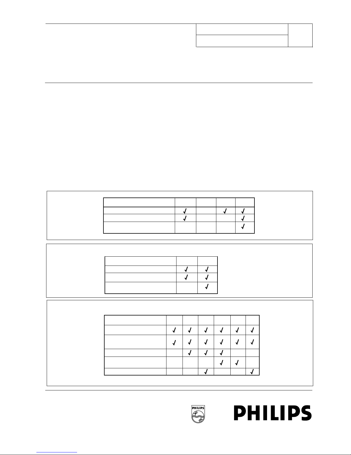
Programming the transceiver is done on two levels:
■System functions such as assigning addresses and
enabling the transceiver functions.
■Functions programmable by the user within the pro-
grammed authorisation (opcode-programmed) by the
installer visible at the transceiver’s alpha-numeric dis-
play.
3.1 SYSTEM SETTINGS BY INSTALLER
Installer programming is possible using two methods:
1. By using the Transceiver Tools software package and
the RS232 transceiver interface unit (Porteq PQ501).
2. By transmitting specific system calls (manually, or by
using the LBB 6000 PC Alpha Desk software package)
as described below.
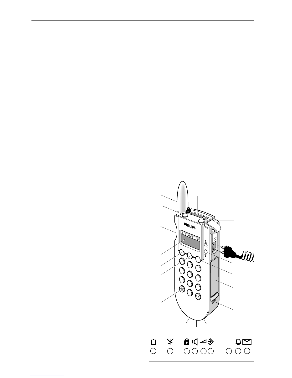
The installer programming can be accessed after setting the
program switch in the battery compartment to the program-
ming position (see figure 6). The transceiver addresses and
operation codes can be programmed with special system calls.
This can be by wireless or while the transceiver is in its storage
rack. When the transceiver is in program mode, its address and
opcode settings can be checked in the alphanumeric display.
When the transceiver is in normal operating mode, the settings
can be viewed using the ‘SHOW CONFIG’ menu option.
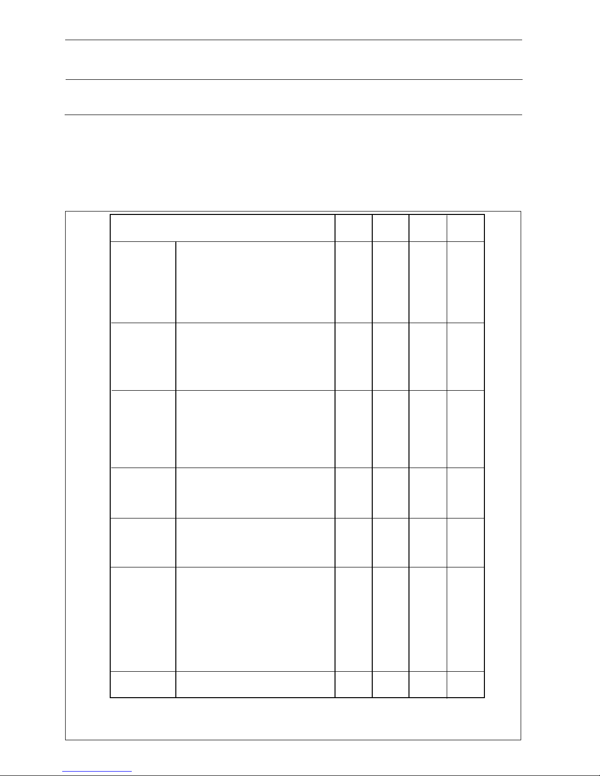
3.1.1 PROGRAMMING AN ADDRESS
A transceiver address can be programmed with the fol-
lowing system call:
■CCC0 N X A3A2A1A0
N= address number to program (0...6)
X= don’t care, normally A
A3A2A1A0= actual address to program
When the PC Alpha Desk software is used to program the
transceiver’s addresses, these system calls are generated auto-
matically.
Seven different addresses can be programmed, two of which
can be used as individual addresses and five as group call
addresses. At least one address must be programmed e.g. the
normal individual call address no.. 1. If the other addresses are
not programmed they will contain the default value ‘CCCC’
which is also the fixed address for the ‘ALL’ call.
Address programming is done with a paging system call and can
be done wireless via the system transmitter or wired while the
transceiver is housed in its storage rack. The programming
switch in the battery compartment must be set to ‘Programme
mode’ The call which programmes addresses in the transceiver
look as follows:
ADDRESS PROGRAMMING USING PC FITTED WITH
LBB 6000 CARD:
- Enter the edit menu in the user programme
- Enter the receiver menu
- Enter the programme addresses menu
- Enter the address number as follows:
0 : Second individual call address
1 : First normal individual call address
2 - 6 : Group call addresses
- Enter the four address digits
- Transmit the call using “F10”
ADDRESS PROGRAMMING USING LBB 5800 DESK
SERIES:
- Press the programme key followed by the “0” key.
- Enter the address number as follows:
0 : Second individual call address
1 : First individual call address
2 - 6 : Group call address
- Enter the selectable address digits ( number of selectable
address digits depend on the programming of the fixed
address digits on the desk)

INSTALLATION INSTRUCTION 83 DP 6000 DIGITAL PAGING SYSTEM
Page 11/29 February 1997.
ADDRESS PROGRAMMING VIA THE PROGRAMMING
KEYBOARD OF LBB 5840 TELEPHONE COUPLER:
First individual address, press
C/CCC0/1/A/A3/A2/A1/A0 (to program address 1)
Second individual address, press
C/CCC0/0/A/A3/A2/A1/A0 (to program address 0)
First group address, press
C/CCC0/2/A/A3/A2/A1/A0 (to program address 2)
Second group address, press
C/CCC0/3/A/A3/A2/A1/A0 (to program address 3)
Third group address, press
C/CCC0/4/A/A3/A2/A1/A0 (to program address 4)
Fourth address, press
C/CCC0/5/A/A3/A2/A1/A0 (to program address 5)
Fifth group address, press
C/CCC0/6/A/A3/A2/A1/A0 (to program address 6)
After each address has been programmed the transceiver will
bleep and the numeric display will show:
A A3A2A1A0
3.1.2 PROGRAM AN OPERATION CODE
To program the functions into the transceiver, 6-different
operation codes are used. Each operation code consists of 6
Hex digits and each digit determines one or a group of func-
tions.
An operation code can be programmed with the following sys-
tem calls:
■CCC M PQRSTU
M = 6 if operation code 1 is programmed in the transceiver
M = 7 if operation code 2 is programmed in the transceiver
M = 8 if operation code 3 is programmed in the transceiver
M = 9 if operation code 4 is programmed in the transceiver
M = A if operation code 5 is programmed in the transceiver
M = B if operation code 6 is programmed in the transceiver
When the PC Alpha Desk software is used to program the
transceiver’s opcodes, these system calls are generated auto-
matically. Note that even when using the Alpha Desk software,
opcode 1 must be programmed as code 6, etc..
Each digit of the operation code is represented by the letters P,
Q, R, S, T, U, and the function or group of functions assigned
to each digit is as follows (for a more in-depth description of
the opcodes, refer to Chapter 3.4):
OPCODE 1
P = Receiver status
Q = Speech status
R = System identity
S = No. of address digits to be displayed
T = Speech time
U = RSSI - level
OPCODE 2
P = Personal bleep pattern 1 on/off rhythm
Q=“““““
R = Personal bleep pattern 1 frequency selection
S=““““ “
T = Pilot tone 1 frequency selection
U = Auto talk-back time
OPCODE 3
P = Personal bleep pattern 2 on/off rhythm
Q=“““““
R = Personal bleep pattern 2 frequency selection
S=““““ “
T = Pilot tone 2 frequency selection
U = Codeinf digit for manual acknowledge in ‘old system
mode’.
OPCODE 4
P = Indication status
Q = User program sign status
R = User program enable status
S = Alarm status
T = Alarm enable status
U = Options
OPCODE 5
P = Fast move level setting
Q = Turn on time no-move/angle alarm
R = Turn-on time fast move
S = Pre-alarm time no-move/angle alarm
T = Pre-alarm time fast move
U = Pre-alarm time tear-off
OPCODE 6
P = Fast charge time (steps of 15 minutes)
Q = Power off enable/disable
R = not used
S = not used
T = not used
U = not used

DP 6000 DIGITAL PAGING SYSTEM INSTALLATION INSTRUCTION 83
February 1997 Page 12/29
The operation code can be programmed into the transceiver
by transmitting a paging system call (wireless via the system
transmitter or wired while the transceiver is stored in its stor-
age rack).
The transceiver programming switch in the battery compart-
ment should be set to the programming mode to make the
transceiver receptive for this system call.
The special programming call for the operation codes look as
follows:
CCC NP QRSTU
N = 6 for programming opcode 1 in the transceiver
N = 7 for programming opcode 2 in the transceiver
N = 8 for programming opcode 3 in the transceiver
N = 9 for programming opcode 4 in the transceiver
N = A for programming opcode 5 in the transceiver
N = B for programming opcode 6 in the transceiver
PQRSTU = 6 digit operation code.
PROGRAMMING THE OPCODES VIA A PC FITTED
WITH THE LBB 6000 CARD:
- Enter the ‘Edit’ menu in the user program
- Select the ‘receiver’ menu item
- Select ‘program opcodes’
- Enter the ‘opcode’ number N as shown above
- Enter the opcode: PQRSTU
PROGRAMMING THE OPCODES VIA THE LBB 5800
DESK SERIES
- Press the PROGRAM key
- Enter the opcode number N as shown above
- Enter the opcode : PQRSTU
PROGRAMMING THE OPCODES VIA THE PROGRAM-
MING KEYBOARD OF TELEPHONE COUPLER LBB 5840
Operation code 1 , press C/CCC6/PQRSTU
Operation code 2 , press C/CCC7/PQRSTU
Operation code 3 , press C/CCC 8/PQRSTU
Operation code 4 , press C/CCC9/PQRSTU
Operation code 5 , press C/CCCA/PQRSTU
Operation code 6 , press C/CCCB/PQRSTU
3.2 USER FUNCTIONS
The transceiver user programming is fully menu driven and can
be accessed as follows:
■Press the MENU key to enter the menu
■Press the UP/DOWN keys to scroll through the menu
■Activate the selected menu item by pressing the ENTER
key.
The menu is closed when no selection is made after 5 seconds.
All of the following functions can be enabled or disabled by
opcode programming. In this description it is assumed all user
programming options are enabled.
3.2.1 SWITCHING ON/OFF
To switch on the transceiver: Press the MENU key, the alpha
display shows: “POWER ON ?” Push the ENTER key within 5
seconds. When the transceiver is switched on, a short acoustic
signal is audible. The alphanumeric display shows the last
received message or “NO MESSAGE”. The numeric display
shows the first individual address.
In ‘new system mode’, the transceiver’s display shows “WAIT-
ING FOR CENTRAL” and after a handshake with the central
will switch on. If the the handshake fails, ‘CENTRAL NOT
RESPONDING’ is displayed after 20 seconds and the trans-
ceiver starts to bleep until the reset button is pressed. After
pressing the reset button, the transceiver switches off.
A hard override is possible by pressing the button sequence
UP/DOWN/LIGHT.
WARNING: The hard override is not detected by the
paging system. Using the hard override can cause conflicts
in the status of the system.
To switch off the transceiver: press the MENU key, scroll
down the menu until “POWER OFF?” is displayed and press
the ENTER key When the transceiver is switched off, a long
acoustic signal is audible.
In ‘new system mode’, the transceiver’s display shows “WAIT-
ING FOR CENTRAL” and after a handshake with the central
the transceiver switches OFF. If the the handshake fails, ‘CEN-
TRAL NOT RESPONDING’ is displayed after 20 seconds and
the transceiver starts to bleep until the reset button is pressed.
After pressing the reset button, the transceiver remains on.
The alphanumeric display shows the last received message or
“NO MESSAGE”.
A hard override is possible by pressing the button sequence
UP/DOWN/LIGHT.
WARNING: The hard override is not detected by the pag-
ing system. Using the hard override can cause conflicts in
the status of the system.

INSTALLATION INSTRUCTION 83 DP 6000 DIGITAL PAGING SYSTEM
Page 13/29 February 1997.
For transceivers without an alpha-numeric display (LBB
6063/02 and LBB 6063/04), the ON and OFF function will be
audible. Changing ON and OFF is done by pushing the ENTER
key, the status is audible by an acoustic sign: a long shut down
bleep means OFF, a short bleep means ON.
A hard override is not possible because the up and down but-
tons are unreachable.
3.2.2 USER SETTINGS
1. GENERAL SETTINGS
Depending on the stroke- and type number the following set-
tings are possible on all transceivers except the LBB 6063/02
and LBB 6063/04. Note that in order for these options to be
made available, they must been enabled using opcode program-
ming. These settings can be activated or toggled using the
ENTER button.
■Power OFF?
All old system transceivers; new systems applicable to
transceivers LBB 6063/.. and LBB 6064/..
■bleep ON/OFF?
toggle the bleep signal on/off (all transceiver types).
Status indicator D.
■bleep LOUD/SOFT?
toggle the volume of the bleep (loud/soft). The volume of
the bleep will change with approximately 20dB (all trans-
ceiver types). Status indicator E.
■pilot 1/2?
toggle between pilot-tone 1 and 2. Status indicator G.
PERSONAL SECURITY TRANSCEIVER
SETTINGS
These settings can be activated or toggled using the ENTER
button.
■No move ON/OFF?
Merged alarms in alpha display (status indicator H)
■Non vertical alarm ON/OFF?
Merged alarms in alpha display (status indicator H)
■Fast move ON/OFF?
Merged alarms in alpha display (status indicator H)
■Tear off ON/OFF?
Merged alarms in alpha display (status indicator H)
■Test request?
Start the PS test procedure between the transceiver
and the central equipment.
3.2.3 LOCKING MESSAGES
The ENTER key is used to toggle locking/unlocking of a display
message. When a message is locked, it can not be erased. This
situation is indicated by a cursor located under the lock sym-
bol.
3.3 DESCRIPTION OF OPCODE AND THEIR
FUNCTIONS
3.3.1 OPCODE 1
Receiver status (Opcode 1 P)
Opcode 1 P Sets the mode of operation of the transceiver
such that it can be used in existing DP6000 systems (old sys-
tem mode) or in systems with a P.C. and LBB 6000 cards and
software as central control unit.
The main difference lies in the fact that a transceiver which is
programmed in ‘new system mode’ expects a handshake with
almost each contact with the central equipment.
The second function in opcode 1 P determines if the last
numeric info remains in the display after a call or that after 12
secs this display will show address 1 again. In the storage rack
the numeric display will always show individual address 1.
Battery saving can be enabled or disabled in opcode 1 P. the
type of battery saving will be with 5F string preambles only.
The last function that is programmed with opcode 1 P is
enabling or disabling the all call (address CCCC).
SPEECH STATUS (OPCODE 1 Q)
The four functions that can be programmed with opcode 1 Q
are :
If always speech after a call is enabled the transceiver will
switch to speech after every call that doesn’t have a “mode
word”. If the call is sent with a ‘mode word’, the speech setting
of the ‘mode word’ has priority over this function.
Speech coupled to codeinf (6 or 7) enables the transceiver
being switched to speech by calls without mode word depend-
ing on the bleep pattern digit. If the codeinf digit is 6 or 7 and
this function is enabled the transceiver will automatically switch
to speech. If the call is sent with a ‘mode word’, the speech
setting of the ‘mode word’ has priority over this function.
If speech busy blocking is enabled the transceiver will not
switch to speech and not use the talk back channel during the
time that speech channel is occupied.
P
ABCD E F G H I

DP 6000 DIGITAL PAGING SYSTEM INSTALLATION INSTRUCTION 83
February 1997 Page 14/29
If field call is enabled the transceiver holder can make a call
from the field to a central desk by pressing the PTT button. For
PS transceivers, the field call is controlled by a handshake pro-
tocol.
SYSTEM IDENTITY (OPCODE 1 R)
The system identity which is transmitted with the “mode
word” in the DP6000 code can be used to separate two neigh-
bouring system which are operated on the same frequency.
This feature can only be used in future systems since all the
encoders in the system must have the possibility to use this
function. For now this digit should be set to 0.
OPCODE 1 S
Opcode I S sets four functions:
The first function determines the dial status of the transceiver
(only applicable if the transceiver includes a dial keypad). Dial
signals can be sent out to the central equipment as DTMF sig-
nals or in DP6000 code. In systems using an LBB 6042 dial cou-
pler, the dial signals should be set to DTMF. If an LBB 6042 is
not used, dial signals can be set to DP6000 code. The advan-
tage of dial signals in DP6000 code is that the transmission time
is much shorter and that the transceiver transmits its own
identity together with the dialling code. The central PC control
desk will then display this information on the PC screen or on
the alpha display of the transceiver that is being called.
The second function setting in opcode 1 S determines whether
calls without numeric info are accepted as valid calls. If calls
‘without info accepted’ is programmed, the transceiver will
respond to both calls without and calls with numeric info.
Using this function in systems where all calls are transmitted
with a numeric message (the message can also contain “– – –
–” it can be guaranteed that only calls where both the address
and numeric info are detected are accepted. The coverage can
be improved by repeating the code string. For example, if a call
is repeated three times and the receiver detects only the
address of the first call, the receiver will not bleep but will be
ready immediately to receive the second repeated call string.
The third function setting in opcode 1 S determines whether
messages with an error(s) will be accepted.
With the last bit in this opcode digit the installer can determine
if the backlight button is used for the display backlight function
or to generate pilot-tone I or II (opposite pilot-tone of the sta-
tus setting). This function can be used to switch something with
one pilot-tone and to open the speech channel with the other
pilot-tone, without having to go through the complete user
programming sequence.
SPEECH TIME (OPCODE 1 T)
Opcode 1 T sets the time duration of the speech call as
required in steps of 10 secs (‘F’ means speech time is unlim-
ited). The speech time should be programmed equally in the
central equipment.
RSSI-LEVEL (OPCODE 1 U)
Opcode digit 1 U sets the level of the squelch detector in the
transceiver. The squelch detector is used to sense if the paging
line is occupied (c.q. for speech busy blocking function). The
value to be set is determined in the factory for each receiver
module, when the module is measured and tested. This is indi-
cated by a sticker found on the receiver module. When this
value is preceded by a ‘U’, the value is valid for the UHF
receiver module LBB 6012; when this value is preceded by a
‘V’, the value is valid for the VHF receiver module LBB 6112).
3.3.2 OPCODES 2 AND 3
PERSONAL BLEEP PATTERNS 1 AND 2
Opcode digits 2 P; Q; R and S and opcode digits 3 P; Q; R and
S are used to set the on/off patterns and frequency patterns for
the personal twin-tone patterns 1 and 2. These personal twin-
tones can be heard in the test mode (twin-tone 1 and twin-
tone 2). Figures 8,9,10,11 and 12 show how the setting of these
opcodes will affect the twin-tone pattern (P and Q switches the
bleep on or off; R and S determine the bleep frequency).
PILOT TONES
Opcode digit 2 T and 3 T sets the frequency for pilot-tones 1
and 2 respectively.
The system is delivered for the pilot-tones 180Hz and 220Hz. If
different pilot-tones should be used also the filters in the trans-
ceivers and in the central receivers and desks should be modi-
fied. The pilot tones have been made programmable for very
special applications where more talk back systems operate on
the same frequency.
The list of the programmable pilot-tones frequencies and the
opcode digits are shown in Chapter 3.4.
AUTO TALK BACK TIME (OPCODE 2 U)
It is possible to switch the PS6000 transceiver to transmission
with a special call from the central (p.c.). In this way the central
operator can hear what is going on at the place where the
transceiver is in case of an alarm.
Opcode digit 2U sets the time that the transmitter stays on in
steps of 5 seconds.
OPCODE 3 U (CODEINF DIGIT FOR MANUAL
ACKNOWLEDGE)
Opcode digit sets the value of the codeinf digit with which a
manual acknowledge is requested in an old system where no
mode words are used (to be used in “old-system-mode”).
In comparison to the second generation PS transceivers, this
function changes as follows:
If a request for manual acknowledge is received, the transceiver
bleeps with bleep-pattern No.3 until the reset button is
pressed. In the ‘new-system-mode’ the request for manual
acknowledge is detected by the ‘mode-word’ in the code. In
the ‘old-system-mode’ where the call-string is transmitted with-
out a ‘mode-word’, the call is detected by the codinf. The cod-
inf which is assigned in the system for request calls for manual

INSTALLATION INSTRUCTION 83 DP 6000 DIGITAL PAGING SYSTEM
Page 15/29 February 1997.
acknowledge, should be set in the opcode digit ‘3 U’ (default
value = 4). If a call is detected on one of the personal addresses
with this assigned bleep-pattern, and the transceiver is pro-
grammed for ‘old-system-mode’, the transceiver will bleep with
bleep-pattern No.3 until the reset button is pressed.
3.3.3 OPCODE 4 (INDICATION STATUS
(OPCODE 4 P)
Opcode digit 4 P sets the following functions :
BLEEP UNTIL RESET.
If this function is enabled the transceiver will bleep when called
until the reset button is pressed, or when the reset button is
not pressed the transceiver will bleep for a maximum duration
of 1 minute.
In PS versions, if an aknowledge is required by the central, for
example - to reset an alarm - the transceiver will emit a bleep
pattern continuously until the reset button is pressed.
LOW BATTERY BLEEP.
An automatic low-battery function is incorporated in the trans-
ceiver. Should the voltage drop below an acceptable level, a
voltage level indicator Fig. 1(A) will illuminate and a bleep-tone
emitted.
In systems with an alphadesk (PC fitted with LBB 6000 card))
the low battery state of the transceiver is sent to the alpha
desk. If acknowledged, the transceiver will remain in operation
for a maximum period of one hour. During this period, ‘low
battery’ will be indicated by a bar sign under the battery symbol
(Fig. 1, indicator (A)). If the batteries are not charged or
changed the transceiver will switch off automatically after this
period.
Before switching off a high volume bleep signal is given. If not
acknowledged by the alpha desk, i.e the transceiver is taken
outside the range of the system, the transceiver switches off
instantly, accompanied by a high volume bleep.
In a system without an alpha desk, the low battery state is indi-
cated by a short bleep which is emitted every two minutes for
a period of up to 1 hour. If no action is taken to charge or
change the batteries during this period, the transceiver will
switch off automatically followed by a high volume bleep signal.
OUT OF RANGE.
Each transceiver is equipped with an out-of range detection
facility. This warns the transceiver carrier that the transceiver
is outside the range covered by the DP6000 system. Out-of
range (see Note) is indicated by a bar sign under symbol Fig. ,
indicator (B) and a bleep signal which bleeps until reset. To
reset the bleep signal press the <Reset> key Fig.1(5). After 32
minutes continuously out-of-range, the transceiver switches off
automatically accompanied with a high volume bleep signal. To
remedy, re-enter the operational range of the DP6000 system
within 32 minutes, or switch the transceiver on again once in
range. When a PS 6000 transceiver is out-of-range an alarm will
always be present at the paging central control. This is due to
the transceiver not responding to check calls (automatically or
manually).
Note: The out-of-range function should be enabled both in the trans-
ceiver and the central equipment.
PERSONAL BLEEP ENABLE/DISABLE.
If the personal bleep is enabled personal bleep pattern 1 (as
programmed in the opcode 2) will sound when the transceiver
is called with codeinf 1 and personal bleep pattern 2 (as pro-
grammed in the opcode 3) will sound when the transceiver is
called with codeinf 2.
(OPCODE 4 Q) USER PROGRAM STATUS
Opcode 4 Q sets the user programming functions to the
required starting position.
(OPCODE 4 R) USER PROGRAM ENABLING
Opcode 4 R allows the installer to enable the choice of user
functions which can be used by the transceiver holder.
(OPCODE 4 S) ALARM STATUS
Opcode 4 S sets the on/off status of the alarms to the required
starting position.
(OPCODE 4 T) ALARM USER ENABLING
Opcode 4 T allows the installer to enable the user to modify
the on/off settings for the alarms via the user programming
menus.
OPTIONS (OPCODE 4 U)
In the last digit (U) of opcode 4 the different options can be
set :
- Location transmission mode.
Location transmission from the transceiver to the central
control desk can be set to take place directly after the
transceiver has received a new location, or only after the
transceiver is scanned by the control desk. The reason for
this programmable option is to provide the installer with
the possibility to avoid to many uncontrolled location calls
in very busy systems. In systems using many transceivers
and/or location transmitters it is advisable to set the trans-
mission of locations to ‘only after the transceiver is
scanned’.
- Manual alarm with audible bleep signal to enable rescuers
to locate the individual at risk, in darkness or smoke.
- Location detection enable/disable.
- No-move coupled to not vertical. If the no-move alarm
should only be transmitted if the angle detection is also
active, the bit in opcode digit 4U for no-move coupled to
not vertical should be set.
IMPORTANT: The angle alarm also should
be disabled and the no-move alarm should be
enabled (opcode digits 4S and 4T).

DP 6000 DIGITAL PAGING SYSTEM INSTALLATION INSTRUCTION 83
February 1997 Page 16/29
3.3.4 OPCODE 5
(OPCODE 5 P) FAST MOVE LEVEL SETTING
With opcode digit 5 P the sensitivity of the fast move detector
can be adjusted.
(OPCODE 5 Q AND R)
TURN ON TIME NO-MOVE / NOT-VERTICAL ALARM
AND FAST-MOVE ALARM
Opcode 5 Q and R sets the times (in steps of 5 and 1 seconds
respectively).The transceiver should detect the no-move / not-
vertical alarm or the fast/move alarm status before it goes in to
the pre-alarm status.
(OPCODE DIGITS 5 S, T AND U)
PREALARM TIMERS
Opcode digits 5 S, T and U sets the time a prealarm status
should last before a real alarm is transmitted to the central
control unit as follows :
Opcode 5 S : prealarm time nomove/not-vertical alarm
(range 0 - 75 secs in steps of 5 seconds)
Opcode 5 T : prealarm time fastmove alarm
(range 0 - 15 secs in steps of 1 second)
Opcode 5 U : prealarm time tear-off alarm
(range 0 - 75 secs in steps of 5 seconds)
3.3.5 OPCODE 6
OPCODE 6 P (FAST CHARGE TIME)
The value of this digit (P x 15 mins) determines the time the
transceiver will be charged with a higher current when the
transceiver is placed in a storage rack. After this time the
charging current will revert to a lower charging current (trickle
mode). This function enables the transceiver batteries to be
fully charged in a shorter time (i.e ≤5hours from empty cells
to fully charged cells).
If a transceiver in the ‘off’ status is placed in the storage rack, it
will always be charged with the higher current for at least 15
minutes.
CAUTION: Never place transceivers with non-recharge-
able batteries in a storage rack with its switch (located in
the battery compartment) placed in the position for
rechargeable batteries.
OPCODE 6 Q (POWER OFF ‘ENABLE/DISABLE’)
The value of this digit determines whether the transceiver car-
rier can switch off the transceiver.
3.4 TABLE OF PILOT TONE FREQUENCIES
With operation codes 2 and 3 the following pilot tones can be
programmed:
Digit Frequency in Hertz
0 100
1 110
2 120
3 130
4 150
5 160
6 180*
7 200*
8 220*
9 240
A 270
B 300
C 330
D 360
E 390
F 430
* These pilot-tone frequencies do not require hardware
changes.
NOTES:
1. A higher pilot tone frequency will be heard louder in the audio sig-
nal.
2. Modifications to the transceiver’s pilot-tone filters are required
when pilot-tone frequencies other than the default values are
used. Adjustments and/or modifications to the pilot-tone filters of
the system equipment may also be necessary.
The following table shows how the pilot-tone in the trans-
ceiver should be modified if non-standard pilot-tone frequen-
cies are used.
Component Standard value New value
C706 10 nF 15 nF
C707 10 nF 15 nF
C708 680 pF 3.3 nF
R114 100 kΩ15kΩ
R715 220 kΩ8.2 kΩ
R719 220 kΩ82 kΩ

3.5 SOFTWARE PROGRAMMING
3.5.1 PREPARATION
To prepare the transceiver for programming set the switch in
the battery compartment to the programming position (A 3).
If the transceiver’s batteries are replaced or an external power
supply is connected, the transceiver will switch on automati-
cally. On the alpha display a bar sign is visible underneath the
programming sign (Fig.1, indicator (F)) and the display indicates
one of the following transceiver versions:
Transceiver Display Functionality
LBB 6063/02 or /04* TB_ND (Talk-back no display)
LBB 6063 TB (Talk-back)
LBB 6064 TB+Dial (Talk-back and dial)
LBB 6065 TB+PS (Talk-back and PS)
LBB 6065 TB+Dial+PS (Talk-back, dial & PS)
* Only when an alphanumeric display is connected.
The second line of the display shows the software release ver-
sion. Indicated as follows:
SW-REL: **.**
* actual value depends on release version.
The receiver is now in the “Service mode” which provides the
following possibilities:
3.5.2 SERVICE AND INSTALLER FUNCTIONS
1 Viewing the addresses
2 Viewing the operation codes
3 Monitor mode
4 Installing mode
5 Test functions
6 Address programming
7 Operation code (opcode) programming
The selection of the above functions should be done as follows:
While the display shows the software version press the down
key. By repeatedly pressing this key the display will show:
“LANGUAGE” (set required language)
“SHOW ADDRESS” (for viewing address function)
“SHOW OPCODE” (for viewing the operation code
function)
“MONITOR” (for the monitor function)
“INSTALLING” (for the installing function)
“TESTING” (for the test function)
“POWER OFF ?” (for the switching off function)
The up/down keys can be used to scroll through the list of
functions.
1. LANGUAGE
- Press the up/down keys until the display shows:
“LANGUAGE”.
- Press the ENTER key.
- Display shows: ENGLISH
Press the down key for the following languages:
GERMAN
FRENCH
USER DEFINED (NEDERLANDS)
Press the ENTER key to set required language.
2. SHOW ADDRESS
- Press the up/down keys until the display shows
“SHOW ADDRESS”.
- Press the ENTER key.
- Display shows: ADDRESS 0
A3A2A1A0*
* Value of actual address.
Using the up/down keys, all the addresses can be
viewed on the display.
To move to another function, press the MENU key
followed by the up/down keys until the required
function is shown in the display.
INSTALLATION INSTRUCTION 83 DP 6000 DIGITAL PAGING SYSTEM
Page 17/29 February 1997.
1
2
3A
B
Location of programming switch

3. SHOW OPCODE
- Press the up/down keys until the display shows
“SHOW OPCODE”.
- Press the ENTER key.
- Display shows: OPCODE 1:
PQRSTU*
* Value of actual opcode.
Using the up/down keys, all the six operation codes can be
viewed on the display.
To move to another function, press the MENU key followed by
the up/down keys until the required function is shown in the
display.
4. MONITOR
The following functions are available in the “Monitor” menu.
Using the up/down keys, all the monitor modes can be viewed
on the display.
Monitor call
Press ENTER to activate this function. While this function is
active the address and numeric information will be displayed
for each call in the system. When a call is received by the
transceiver, the display shows (when present in the call):
Call <address><codinf>
<numeric info> <mode word>
To move to another monitor function, press the up/down keys
until the required function is shown in the display.
Monitor message
Press ENTER to activate this function. While this function is
active the alphanumeric information will be displayed for each
alpha call in the system.
To move to another monitor function, press the up/down keys
until the required function is shown in the display.
Monitor speech / RSSI
Press ENTER to activate this function. While this function is
active, the transceiver will go in to the speech mode, and
speech can be monitored in the system, and the received HF
field strength is shown as an RSSI opcode value. This RSSI value
is only meant for system testing.
To move to another monitor function, press the up/down keys
until the required function is shown in the display.
Monitor Call counter
Press ENTER to activate this function. The transceiver will
count the calls addressed to address 0 transmitted by the sys-
tem, starting when this function is activated.
The display shows: CALL COUNTER
<count>
To move to another monitor function, press the up/down keys
until the required function is shown in the display.
Monitor Location
Press ENTER to activate this function. While this function is
active the display will show the last received location address.
This function can be used to test the location receiver or to
site-test the range and placement of different location transmit-
ters.
The display shows: LOCATION
<location address>
To move to another monitor function, press the up key until
the required function is shown in the display. To move to
another function, press the MENU key followed by the up key
until the required function is shown in the display.
5. INSTALLING
The following functions are available in the “Installer mode”.
Using the up/down keys, all the installing modes can be viewed
on the display.
SET DEFAULTS
When set defaults is activated, the receiver address and opera-
tion codes are set into default values. All quick-dial numbers
are cleared. To activate this function proceed as follows:
When the display shows INSTALLING press the ENTER key.
The display shows:
SET DEFAULTS
To activate this function press the <Enter> key once again. The
display shows:
SET DEFAULTS
BUSY
After the default setting has been done, the display shows:
SET DEFAULTS
READY
Use the up/down keys to go to the next function available
within the menu.
Use the MENU key, followed by a up/down keys to exit the
installing functions.
The default settings are:
Address 0 - 6 CCCC
Opcode 1 : 560047
Opcode 2 : 0F056A
Opcode 3 : B71D84
Opcode 4 : 4CE0F9
Opcode 5 : 765631
Opcode 6 : 080000
CAUTION: Returning the transceiver to its default set-
tings, will set the programmed RSSI value to its default
value. Please re-program this value according to the label
on the receiver module.
DP 6000 DIGITAL PAGING SYSTEM INSTALLATION INSTRUCTION 83
February 1997 Page 18/29

SERIAL COMM.
The transceiver has been prepared to enable it to download
new software and settings by using the Transceiver Tools soft-
ware package and the RS232 transceiver interface unit (Porteq
PQ501). Please refer to service information 4822 861 35085.
To move to another function, press the MENU key followed by
the up/down keys until the required function is shown in the
display.
6. TESTING
The following functions are available in the “Test mode”. Using
the up/down keys, all the installing modes can be viewed on the
display. All tests will be active for approx.. four seconds.
- DISPLAY TEST
All segments in the numeric display will be activated, and the
alpha-numeric display will show checkered test characters in all
its segments.
- LED TEST
The four back-light LEDs to illuminate the displays and the
green receiver LED will illuminate.
- TWINTONE 1
To listen to the personal bleep pattern 1, that has been
installed via the opcodes.
- TWINTONE 2
To listen to the personal bleep pattern 2, that has been
installed via the opcodes.
- TX TALKBACK
When this test is enabled, the transmitter is switched on,
speech will be enabled, the pilot-tone is transmitted and the
red transmitter LED is illuminated. This function is used for
test purposes such as: checking the carrier frequency; checking
the frequency deviation of the pilot-tone and speech. And of
course the transmitter LED.
- TX DP6000
When this test is enabled, the transmitter is switched on and
will continuously transmit DP6000 code ‘F’. This function is
used to check the functionality of the DP6000 code generator.
The frequency of the ‘F’ code is approximately 692 Hz. This
function is also used to test the frequency deviation when
DP6000 code is transmitted.
- TX DTMF
When this test is enabled, the transmitter is switched on and
will transmit a DTMF code outside the normal DTMF range.
This function is to check the frequency deviation during DTMF
transmission. (LBB 6064/LBB 6066 only)
- RSSI OPCODE
For factory purposes only.
- ALARM TEST
The alarm test is used to test the available alarm functions. (PS
versions only) The alarms are tested as follows and in this
sequence:
1) Press the manual alarm button. A short bleep is audible
and the display shows:
ALARM TEST
MANUAL
2) Hold the transceiver still and vertical. A short bleep is audi-
ble and the display shows:
ALARM TEST
NO MOVE
3) Shake the transceiver until a short bleep is audible. The dis-
play shows:
ALARM TEST
FAST MOVE
4) Place the transceiver horizontally and still. A short bleep is
audible and the displays:
ALARM TEST
NOT VERTICAL
After a brief moment a second bleep is audible and the dis-
play shows:
ALARM TEST
NO MOVE
5) If present, remove the tear-off contact. A short bleep is
audible and the display shows:
ALARM TEST
TEAROFF
- DIALKEY TEST
When this test is enabled the display will show:
DIALKEY TEST
ENABLED
When any of the dial-keys is pressed, the display shows:
DIALKEY TEST
<key>
- COMM. TEST
As long as this test is enabled, there will be a continuous hand-
shake between the transceiver and the central equipment. The
handshake is confirmed by audible bleeps by the transceiver.
This function is used for site tests (e.g. coverage).
7. POWER OFF ?
Use the up/down keys to select this function. The display will
show:
POWER OFF?
Press ENTER to switch the transceiver off. There will be no
handshake with the central equipment when the transceiver is
in installer mode.
INSTALLATION INSTRUCTION 83 DP 6000 DIGITAL PAGING SYSTEM
Page 19/29 February 1997.

DP 6000 DIGITAL PAGING SYSTEM INSTALLATION INSTRUCTION 83
February 1997 Page 20/29
The following tables show the default values of each function
and a box is provided so that the installer can enter the value
set. At the end of the table the complete 6 opcodes can be
entered.
OPERATION CODE 1 Default valueValue set
Old system mode enabled
Info remains in numeric display after call
Battery saving (5F) enabled
ALL call enabled
0
4
0
1
8
4
2
1==P = P5
Receiver status
Always speech after a call
Speech if codeinf. = 6 or 7
Speech busy blocking enable
Field call enabled
0
4
2
0
8
4
2
1
0
0
0
0
0
0
0
0
0
0
==Q = Q
= R
6
=0
==
00
0
Speech status
System identity
(range HEX 0 - HEX 3)
Dial signals transmitted as DP6000/DTMF
(0 = DP6000, 1 = DTMF)
Calls without info accepted (0 = calls must
contain numeric info message)
Not used
Not used
Error(s) in Message accepted (1=accept)
Back-light button is pilot-tone switch
= R
= S
System Identity
Dial status
Speech time
RSSI level
Speech time
(0 to 14 in steps of 10 secs.)
15 (HEX F) = Infinite speech time
RSSI Level
(range HEX Ø - HEX F)
= T = T
= S
4
= U = U
7
Table of contents
Other Philips Transceiver manuals