Icom IC-F1710 User manual

INSTRUCTION MANUAL
UHF MOBILE TRANSCEIVER
iF2810
iF2710
VHF MOBILE TRANSCEIVER
iF1810
iF1710
Above photo shows the IC-F1810 or IC-F2810.

IMPORTANT
READ ALL INSTRUCTIONS carefully and com-
pletely before using the transceiver.
SAVE THIS INSTRUCTION MANUAL — This
instruction manual contains important operating instructions
for the IC-F1710, IC-F1810, IC-F2710 and IC-F2810 VHF/
UHF MOBILE TRANSCEIVERS.
See the operating guide for details of MDC 1200 system
operation. Consult your Icom dealer or system operator
for details concerning your transceivers programming.
EXPLICIT DEFINITIONS
WORD DEFINITION
RWARNING Personal injury, fire hazard or electric
shock may occur.
CAUTION Equipment damage may occur.
NOTE
If disregarded, inconvenience only. No risk
of personal injury, fire or electric shock.
Icom, Icom Inc. and the Icom logo are registered trademarks of Icom Incor-
porated (Japan) in Japan, the United states, the United Kingdom, Germany,
France, Spain, Russia and/or other countries.
All other products or brands are registered trademarks or trademarks of their
respective holders.
i

PRECAUTIONS
RWARNING! NEVER connect the transceiver to an
AC outlet. This may pose a fire hazard or result in an electric
shock.
RWARNING! NEVER connect the transceiver to a
power source of more than 16 V DC such as a 24 V battery.
This connection will ruin the transceiver.
RWARNING! NEVER cut the DC power cable be-
tween the DC plug and fuse holder. If an incorrect connection
is made after cutting, the transceiver might be damaged.
RWARNING! NEVER place the transceiver where
normal operation of the vehicle may be hindered or where it
could cause bodily injury.
CAUTION! NEVER allow children to touch the trans-
ceiver.
CAUTION! NEVER expose the transceiver to rain,
snow or any liquids.
USE the specified microphone only. Other microphones
have different pin assignments and may damage the trans-
ceiver.
DO NOT use or place the transceiver in areas with tem-
peratures below –25°C or above +55°C, or in areas subject to
direct sunlight, such as the dashboard.
DO NOT operate the transceiver without running the ve-
hicle’s engine. The vehicle’s battery will quickly run out if the
transceiver transmits while the vehicle’s engine OFF.
DO NOT place the transceiver in excessively dusty envi-
ronments.
DO NOT place the transceiver against walls. This will ob-
struct heat dissipation.
DO NOT use chemical agents such as benzine or alcohol
when cleaning, as they damage the transceiver surfaces.
BE CAREFUL! The transceiver will become hot when
operating continuously for long periods.
Approved Icom optional equipment is designed for optimal
performance when used with an Icom transceiver.
Icom is not responsible for the destruction or damage to an
Icom transceiver in the event the Icom transceiver is used
with equipment that is not manufactured or approved by
Icom.
ii

iii
TABLE OF CONTENTS
IMPORTANT.......................................................................... i
EXPLICIT DEFINITIONS....................................................... i
PRECAUTIONS.................................................................... ii
TABLE OF CONTENTS....................................................... iii
1 PANEL DESCRIPTION................................................1–7
n Front panel ...................................................................1
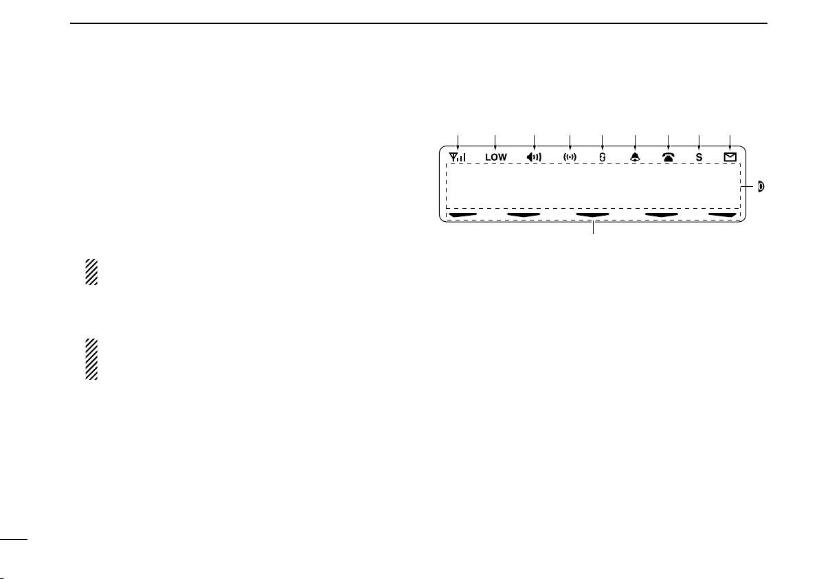
n Function display ...........................................................2
n Programmable function keys........................................3
2 BASIC OPERATION..................................................8–13
nTurning power ON ........................................................8
nChannel selection.........................................................8
n Call procedure..............................................................9
nReceiving and transmitting...........................................9
nScrambler function .....................................................12
nUser set mode............................................................13
3 BIIS OPERATION ....................................................14–24
nDefault setting ............................................................14
nReceiving a call ..........................................................14
nTransmitting a call.......................................................16
n Receiving a message.................................................18
n Transmitting a status...................................................20
n Transmitting an SDM (Short Data Message)..............21
nPosition data transmission..........................................23
nPrinter connection ......................................................23
nDigital ANI ..................................................................23
nAuto emergency transmission ....................................23
nStun function ..............................................................24
nBIIS indication ............................................................24
nPriority A channel selection........................................24
nHorn output ................................................................24
4 CONNECTION AND MAINTENANCE ....................25–29
nRear panel connection ...............................................25
nSupplied Accessories.................................................26
nMounting the transceiver ............................................27
nOptional UT-109 or UT-110 installation.......................27
nOptional OPC-617 installation ....................................... 28
n Antenna......................................................................29
n Fuse replacement ......................................................29
n Cleaning .....................................................................29
n Options.......................................................................29
5 DOC .........................................................................30–31

I c o m I n c
oi
qe*w
e*
IC-F1710
F2710
IC-F1810
F2810
y ru t
nFront panel
qAF VOLUME CONTROL KNOB
Rotate the knob to adjust the audio output level.
• Minimum audio level is pre-programmed.
wFUNCTION DISPLAY (p. 2)
Displays a variety of information, such as an operating
channel number/name, 5-tone code, DTMF numbers and
audible condition, etc.
eDIAL or UP/DOWN KEYS
• IC-F1710, F2710: DIAL
Rotate to select an operating channel, etc.
• IC-F1810, F2810: UP/DOWN Keys
Push to select an operating channel, etc.
*The desired function can be assigned by your dealer. (p. 3)
r10-KEYPAD (IC-F1810 or IC-F2810 only)
The keypad allows you to enter digits to:
• Select memory channels, tone channels and DTMF codes (when
in the DTMF code channel selection mode)
• Set TX codes and BIIS status number
• Input text message for SDM operation
• Start up with a password
tBUSY INDICATOR
Lights green while receiving a signal, or when the squelch
is open.
1
1
PANEL DESCRIPTION
1
2
3
4
5
6
7
8
9
10
11
12
13
14
15
16

2
1PANEL DESCRIPTION
yPOWER SWITCH [POWER]
Push to turn the power ON and OFF.
• The following functions are available at power ON as options:
- Automatic scan start
- Password prompt
- Set mode
uTRANSMIT INDICATOR
Lights red while transmitting.
iDEALER-PROGRAMMABLE KEYS
Desired functions can be programmed independently by
your dealer. (p. 3)
In this instruction manual, these keys are from the left,
called [P0]/[P1]/[P2]/[P3]/[P4].
oMICROPHONE CONNECTOR
Connect the supplied microphone or optional DTMF micro-
phone.
NEVER connect non-specified microphones. The pin
assignments may be different and the transceiver may
be damaged.
ï MICROPHONE
The supplied or optional microphone has a PTT switch and
a hanger hook.
• The following functions are available when the microphone is on or
off hook:
- Automatic scan start when on hook.
- Automatic priority channel selection when off hook.
- Sets to ‘Inaudible’ condition (mute condition) when on hook.
- Sets to ‘Audible’ condition (unmute condition) when off hook.
nFunction display
1 3 6 . 1 N a r
!1
!0
q w e r t y u i o
qSIGNAL STRENGTH INDICATOR
Indicates relative signal strength level.
wLOW POWER INDICATOR
Appears when low output power is selected.
eAUDIBLE INDICATOR
➥ Appears when the channel is in the ‘audible’ (unmute)
condition.
➥ Appears when the specified 5-tone/BIIS code is re-
ceived.
rCOMPANDER INDICATOR
Appears when the compander function is activated.
tSCRAMBLER INDICATOR
Appears when the voice scrambler function is activated.

3
1
PANEL DESCRIPTION
1
yBELL INDICATOR
Appears/blinks when the specific 5-tone/BIIS code is re-
ceived, according to the pre-programming.
uCALL CODE MEMORY INDICATOR
Appears when the call code memory is selected.
iSDM MEMORY INDICATOR
Appears when the SDM memory is displayed.
oSDM INDICATOR
Appears when an SDM is received, or a transmit SDM is
selected.
!0 ALPHANUMERIC DISPLAY
Displays an operating channel number, channel name, Set
mode contents, DTMF code, etc.
The indication mode can be selected from 1 line or 2 lines.
Ask your dealer for details.
In this instruction manual, the LCD illustration is described
using the 2 lines indication mode.
!1 ACTIVATED KEY INDICATOR
Appears above the key assigned as [DIGITAL] key when
that key has been activated.
nProgrammable function keys
The following functions can be assigned to [DIAL]*, [UP],
[DOWN], [P0], [P1], [P2], [P3] and [P4] programmable func-
tion keys.
Consult your Icom dealer or system operator for details con-
cerning your transceivers programming.
If the programmable function names are bracketed in the fol-
lowing explanations, the specific key is used to activate the
function depends on the programming.
*The functions you can assign to [DIAL] are limited.
(Only functions marked with Ican be assigned.)
ICH UP AND DOWN KEYS
➥Push (or Rotate)* to select an operating channel.
➥Push (or Rotate)* to select a transmit code channel after
pushing [TX Code CH Select].
➥Push (or Rotate)* to select a DTMF channel after pushing
[DTMF Autodial].
➥Push (or Rotate)* to select a scan group after pushing and
holding [Scan A Start/Stop]/[Scan B Start/Stop].
➥Push (or Rotate)* to select a BIIS code, status number or
SDM after pushing [Digital].
*Rotate when this function is assigned to [DIAL].
IZONE UP AND DOWN KEY (This function is for [DIAL] only)
Rotate to select the desired zone.

4
1PANEL DESCRIPTION
ZONE KEY
Push this key, then select the desired zone using [CH Up]/
[CH Down].
What is “zone”?—The desired channels are assigned into
a zone according to the intended use for grouping.
For example, ‘Staff A’ and ‘Staff B’ are assigned into a
“Business” zone, and ‘John’ and ‘Cindy’ are assigned into a
“Private” zone.
SCAN A START/STOP KEY
➥This key’s operation depends on the Power ON Scan setting.
When the power ON scan function is turned OFF;
Push to start and cancel scanning operation. In case of
transmission during scan, cancels scanning.
When the power ON scan function is turned ON;
Push to pause scanning.Scanning resumes after a specified
time period has passed. In case of transmission during scan,
pauses scanning. Scanning resumes after a specified time
period has passed after the transmission is finished.
➥Push and hold this key for 1 sec. to indicate the scan group,
then select the desired group using [CH Up]/[CH Down].
SCAN B START/STOP KEY
➥Push to start and cancel scanning operation. In case of
transmission during scan, pauses scanning. Scanning re-
sumes after a specified time period has passed after the
transmission is finished.
➥Push and hold this key for 1 sec. to indicate the scan
group, then select the desired group using [CH Up]/
[CH Down].
SCAN ADD/DEL (TAG) KEY
Push to add or delete the selected channel to/from the scan
group.
PRIO A/B KEYS
➥Push to select Priority A or Priority B channel.
➥Push and hold [Prio A (Rewrite)] to rewrite the Prio A chan-
nel.
MR-CH 1/2/3/4 KEYS
Push to select an operating channel directly.
MONI (AUDI) KEY
Activates one of (or two of) the following functions on each
channel independently:
• Push and hold to un-mute the channel (audio is emitted; ‘Audible’
condition).
• Push to mute the channel (sets to ‘Inaudible’ only).
• Push to un-mute the channel (sets to ‘Audible’ only).
• Push after the communication is finished to send a ‘reset code’.
NOTE: The un-mute condition (‘Audible’ condition) may au-
tomatically return to the mute condition (‘Inaudible‘ condi-
tion) after a specified period depending on programming.

5
1
PANEL DESCRIPTION
1
PUBLIC ADDRESS KEY
While in the hailer mode, push this key for the audio output via
the hailer amplifier. Ask your dealer for details.
While in the normal mode, the audio output via the cable can
be controlled from the transceiver separately from [VOL] control
knob when an optional OPC-617 acc cable is installed.
• This audio output can be used as a ‘public address’ function when an
external audio amplifier and speaker are connected additionally.
• Push this key, then speak into the microphone while pushing the
PTT switch.
• [CH Up]/[CH Down] allow you to set the audio output level from
minimum to maximum.
RX SPEAKER KEY
While in the hailer mode, the external speaker drive function
is also available simultaneously when the external connec-
tions are made for the ‘public address’ function. The received
audio can be heard via the external speaker when this key is
pushed.
• This function is useful when you are out of the vehicle.
• The audio output level is linked to the transceiver’s volume control.
LIGHT KEY
Push to turn the transceiver’s backlight ON for about 5 sec.
when the backlight function is turned OFF in user set mode.
LOCK KEY
Push and hold to electronically lock all programmable keys
except the following:
[Call] (incl. Call A and Call B), [Moni(Audi)] and [Emergency].
HIGH/LOW KEY
Push to select the transmit output power temporarily or per-
manently, depending on the pre-setting.
• Ask your dealer for the output power level for each selection.
C.TONE CH ENT KEY
Push to select the continuous tone channel using [CH Up]/
[CH Down] to change the tone frequency/code setting after
pushing this key. The selected channel remains set as the
continuous tone channel until another channel is designated
as such.
TALK AROUND KEY
Turn the talk around function ON and OFF.
• The talk around function equalizes the transmit frequency to the
receive frequency for transceiver-to-transceiver communication.
WIDE/NARROW KEY
Push to toggle the IF bandwidth between wide and narrow.
• The wide passband width can be selected from 25.0 or 20.0 kHz
using the CS-F70/F1700 cloning software. Ask your Dealer for
details.
DTMF AUTODIAL KEY
➥Push to enter the DTMF channel selection mode.Then select
the desired DTMF channel using [CH Up]/[CH Down].
➥After selecting the desired DTMF channel, push this key to
transmit the DTMF code.

6
1PANEL DESCRIPTION
RE-DIAL KEY
Push to transmit the last-transmitted DTMF code.
CALL KEYS
Push to transmit a 5-tone/BIIS ID code.
• Call transmission is necessary before calling another station depend-
ing on your signalling system.
• [Call A] and/or [Call B] may be available when your system employs
selective ‘Individual/Group’ calls. Ask your dealer which call is
assigned to each key.
EMERGENCY KEYS
➥Push and hold to transmit an emergency call.
➥When [Emergency Single (Silent)] or [Emergency Repeat
(Silent)] is pushed, an emergency call is transmitted with-
out a beep emission and LCD indication change.*
• If you want to cancel the emergency call, push (or push and hold)
the key again before transmitting the call.
• The emergency call is transmitted one time only or repeatedly
until receiving a control code depending on the pre-setting.
*BIIS PMR operation only
SURVEILLANCE KEY
Push to turn the surveillance function ON or OFF.
When this function is turned ON, the beep is not emitted and
the LCD backlight does not light when a signal is received or
a key is pushed, etc.
TX CODE ENTER KEY
Push to enter the ID code edit mode directly, for both 5-
tone and BIIS. Then set the desired digit using [CH Up]/
[CH Down] or 10-keypad*. (p. 11)
*IC-F1810 or IC-F2810 only
TX CODE CHANNEL SELECT KEY
➥
Push to enter the ID code channel selection mode directly.
Then set the desired channel using [CH Up]/[CH Down].
(p. 10)
➥During ID code channel selection mode, push for 1 sec. to
enter the ID code edit mode for 5-tone and BIIS. Then set
the desired digit using [CH Up]/[CH Down] or 10-keypad*.
(p. 11)
*IC-F1810 or IC-F2810 only
ITX CODE CHANNEL UP/DOWN KEYS
Push (or Rotate)* to select a TX code channel directly.
*Rotate when this function is assigned to [DIAL].
ID-MR SELECT KEY
➥Recalls detected ID codes.
• Push this key, then select the ID code using [CH Up]/[CH
Down].
• Up to 5 ID’s are memorized.
➥Push and hold to erase the selected ID’s.
SCRAMBLER KEY
Push to toggle the voice scrambler function ON and OFF.

7
1
PANEL DESCRIPTION
1
COMPANDER KEY
Push to toggle the compander function ON and OFF.
The compander function reduces noise components from the
transmitted audio to provide clear communication.
HOOK SCAN KEY
When the hook on scan function is turned ON, push this key
to stop scanning temporarily. Push this key again to re-start
scanning.
USER SET MODE KEY
➥Push and hold to enter user set mode.
• During user set mode, push this key to select an item, and change
the value or condition using push [CH Up]/[CH Down].
➥Push and hold this key again to exit user set mode.
User set mode is also available via the ‘Power ON function.’
Refer to p. 13 also.
OPT 1/2/3 KEYS
Push to control the output signal level of the optional ports in
the optional unit connector.
DIGITAL BUTTON KEY (BIIS operation only)
➥Push to select the call ID list, transmit message and
standby condition. Toggles between queue channel and
received message record indication after queue channel
is selected.
➥Push and hold to select queue channel indication.
ISTATUS UP/DOWN KEYS (BIIS operation only)
➥While in the standby condition, push (or rotate)* to display
the transmit status indication and select a status number.
➥When a received SDM is displayed, push (or rotate)* to
cancel the automatic scroll and scroll the message manu-
ally.
➥When an SDM that contains more than 12 characters is dis-
played, push (or rotate)* to scroll the message manually.
*Rotate when this function is assigned to [DIAL].

8
2BASIC OPERATION
nTurning power ON
qPush [ ] to turn the power ON.
wIf the transceiver is programmed for a start up password,
input the digit codes as directed by your dealer.
• 10-keypad* can be used for password input.
*IC-F1810 or IC-F2810 only
• The keys as below can be used for password input:
The transceiver detects numbers in the same block as identical.
Therefore “01234” and “56789” are the same.
KEY
NUMBER 0
5
4
9
3
8
2
7
1
6
P0 P4P3P2P1
P0 P4P3P2P1
In this instruction manual, these keys are
from the left, called [P0]/[P1]/[P2]/[P3]/[P4].
eWhen the “PASSWORD” indication does not clear after in-
putting 6 digits, the input code number may be incorrect.
Turn the power off and start over in this case.
nChannel selection
Several types of channel selections are available. Methods
may differ according to your system set up.
NON-ZONE TYPE:
Push [CH Up] or [CH Down], or rotate [CH Up/Down] to select
the desired operating channel, in sequence; or, push one of
[MR-CH 1] to [MR-CH 4] keys to select a channel directly.
ZONE TYPE:
Push [Zone] then push [CH Up] or [CH Down], or rotate [Zone
Up/Down] to select the desired zone.
AUTOMATIC SCAN TYPE:
Channel setting is not necessary for this type. When turn-
ing power ON, the transceiver automatically starts scanning.
Scanning stops when receiving a call.

9
2
BASIC OPERATION
2
nCall procedure
When your system employs tone signaling (excluding CTCSS
and DTCS), the call procedure may be necessary prior to voice
transmission. The tone signalling employed may be a selective
calling system which allows you to call specific station(s) only
and prevent unwanted stations from contacting you.
qSelect the desired TX code channel or 5-tone code accord-
ing to your System Operator’s instructions.
• This may not be necessary depending on programming.
• Refer to pgs. 10–11 for selection.
wPush the call key (assigned to one of the dealer program-
mable keys) or [PTT].
eAfter transmitting, the remainder of your communication
can be carried out in the normal fashion.
Selective calling Non-selective calling
nReceiving and transmitting
Receiving:
qPush [ ] to turn the power ON.
wPush [CH Up] or [CH Down], or rotate [CH Up/Down] to
select a channel, in sequence.
eWhen receiving a call, adjust the audio output level to a
comfortable listening level.
Transmitting:
Wait for the channel to become clear to avoid interference.
qTake the microphone off hook.
• 5-tone mute may be released. (The ‘audible’ condition is selected
and BUSY indicator lights green.)
• A priority channel may be selected automatically.
wWait for the channel to become clear.
• The channel is busy when BUSY indicator lights green.
ePush [CALL] when initiating a call from your side.
• Coded audio may be heard from the transceiver, then “ ” ap-
pears.
• This operation may not be necessary depending on your signal-
ing system. Ask your dealer for details.
rWhile pushing and holding [PTT], speak into the micro-
phone at your normal voice level.
tRelease [PTT] to receive.
IMPORTANT: To maximize the readability of your signal;
1. Pause briefly after pushing [PTT].
2. Hold the microphone 5 to 10 cm from your mouth, then
speak into the microphone at a normal voice level.

10
2BASIC OPERATION
ïTransmitting notes
• Transmit inhibit function
The transceiver has several inhibit functions which restrict
transmission under the following conditions:
- The channel is in mute condition (‘Inaudible’ condition;
“” does not appear.)
- The channel is busy.
- Un-matched (or matched) CTCSS is received.
(Depending on the pre-setting.)
- The selected channel is a ‘receive only’ channel.
• Time-out timer
After continuous transmission for the pre-programmed time
period, the time-out timer is activated, causing the transceiver
to stop transmitting.
• Penalty timer
Once the time-out timer is activated, transmission is further
inhibited for a period determined by the penalty timer.
ïTX code channel selection
If the transceiver has [TX Code CH Select] assigned to it,
the indication can be toggled between the operating channel
number (or name) and TX code channel number (or name).
When the TX code channel number (or name) is displayed,
[CH Up]/[CH Down] selects the TX code channel.
USING [TX CODE CH SELECT] KEY:
qPush [TX Code CH Select]— a TX code channel number
(or name) appears.
wPush [CH Up] or [CH Down], or rotate [CH Up/Down] to
select the desired TX code channel.
ePush [Call] (or [PTT] during BIIS operation) to transmit the
selected TX code.
USING [TX CODE CH UP]/[TX CODE CH DOWN] KEY:
If the transceiver has a [TX Code CH Up], [TX Code CH Down]
or [TX Code CH Up/Down] key assignment, the programmed
TX code channel can be selected directly when pushed or
rotated.
NOTE for PMR or BIIS PMR operation:
• The LCD indication does not change when the operating
channel number (or name) is displayed. (Depending on
the pre-setting)
•
To check the selected TX code, push [TX Code CH Select].

11
2
BASIC OPERATION
2
ïTX code number edit
If the transceiver has [TX Code CH Select] or [TX Code Enter]
assigned to it, TX code contents can be edited within the al-
lowable digits.
USING [TX CODE CH SELECT] KEY:
qPush [TX Code CH Select] to enter the TX code channel
selection mode.
• Select the desired channel before entering the TX code channel
selection mode if necessary.
wPush [TX Code CH Select] for 1 sec. to enter the TX code
edit mode.
ePush [TX Code CH Select] to select the desired digit to
be edited.
• The digit to be edited blinks.
rPush [CH Up], [CH Down] or 10-keypad*, or rotate [CH
Up/Down] to set the desired digit.
tPush [TX Code CH Select] to set the digit. The digit to the
right will blink automatically.
• When the 10-keypad* is used for setting, the digit to the right will
blink automatically without pushing [TX Code CH Select].
yRepeat rand tto input all allowable digits.
uPush [Call] or [PTT] to transmit the edited TX code.
*IC-F1810 or IC-F2810 only
USING [TX CODE ENTER] KEY:
qSelect the desired TX code channel via [TX Code CH
Select]+[CH Up] or [CH Down], [TX Code CH Up], [TX
Code CH Down] or [TX Code CH Up/Down].
wPush [TX Code Enter] to enter the TX code edit mode.
ePush [TX Code Enter] to select the desired digit to be ed-
ited.
• The digit to be edited blinks.
rPush [CH Up], [CH Down] or 10-keypad*, or rotate [CH
Up/Down] to set the desired digit.
tPush [TX Code Enter] to set the digit. The digit to the right
will blink automatically.
• When the 10-keypad* is used for setting, the digit to the right will
blink automatically without pushing [TX Code CH Select].
yRepeat rand tto input all allowable digits.
uPush [Call] or [PTT] to transmit the edited TX code.
*IC-F1810 or IC-F2810 only

12
2BASIC OPERATION
ïDTMF transmission
If the transceiver has [DTMF Autodial] assigned to it, the auto-
matic DTMF transmission function is available. Up to 8 DTMF
channels are available.
TO SELECT A TX CODE:
qPush [DTMF Autodial]— a DTMF channel appears.
wPush [CH Up] or [CH Down], or rotate [CH Up/Down] to
select the desired DTMF channel.
ePush [DTMF Autodial] to transmit the DTMF code in the
selected DTMF channel.
nScrambler function
The voice scrambler function provides private communication
between stations.The frequency inversion type is equipped to
all versions, moreover, the optional Rolling or Non-rolling type
can be available.
qPush [Scrambler] to turn the scrambler function ON.
• “ ” appears.
wPush [Scrambler] again to turn the scrambler function
OFF.
• “ ” disappears.

13
2
BASIC OPERATION
2
nUser set mode
User set mode can be accessed with ‘Power ON’ function. In
this case, all set mode items are available.
User set mode allows you to set seldom-changed settings
and you can “customize” the transceiver operation to suit your
preferences and operating style
Entering the user set mode:
qWhile pushing and holding [P1] and [P2], push [ ] to turn
the power ON. Then, push and hold [P0] to enter user set
mode.
[P1][P0] [P2] [ ]
wPush [P0] several times to select the appropriate item.
Then, push [Up] or [Down] or rotate [DIAL] to set the de-
sired level/condition.
• Available set mode functions are Backlight, LCD Contrast,
Beep, Beep Level, Ringer Level, SQL Level, AF Min Level,
Mic Gain, Horn and Signal Moni.
[P0] [Up]/[Down] or [DIAL]
ePush [ ] again to exit set mode.
[ ]
User set mode is also available using a programmable key.
Please refer to p. 7 [User Set Mode] section for instructions
regarding using the key assigned for user set mode.
[User Set Mode] is allowed for the quick item selection. Set
“Enable” for the often used items with the CS-F70/F1700
cloning software.

14
3BIIS OPERATION
nDefault setting
The following functions are assigned to each programmable
key as the default. However, the assigned function can be
changed by your dealer. Ask your dealer for details.
NOTE: [TX Code Enter] must be assigned to a key.
P0 P4P3P2P1
In this instruction
manual, these keys
are from the left,
called [P0]/[P1]/
[P2]/[P3]/[P4].
[P0]; Call : Push to transmit a 5-tone/BIIS call
when the selected channel is a 5-
tone or BIIS channel.
[P1]; Digital :
Push to select the call list ID/transmit
message, or to display the receive
message record for selection.
[P3]; TX Code Enter : Push to enter the ID code edit mode
directly for both 5-tone and BIIS.
[P4]; Moni(Audi) :
Push this key after the communication
t
o send a ‘Clear down’ signal during
BIIS channel operation.
[P2]; Null : No function is assigned.
[Up]/[Down]/[DIAL]; CH Up/Down
: While in the standby condition, se-
lects the operating channel.
After pushing [Digital] or [TX Code CH
Select], selects call list or TX code
channel, respectively.
nReceiving a call
ïIndividual call
qWhen an individual call is received;
• Beeps sound.
• “ ” appears and the mute is released.
• The programmed text message (e.g.“CALLING”) and the call-
ing station ID (or text) is displayed when the indication mode is 2
lines.
• The programmed text message (e.g.“CALLING”) and the calling
station ID (or text) is displayed alternately when the indication
mode is 1 line, depending on the setting.
• “ ” appears or blinks depending on the setting.
Appears or blinksAppears
CALLING
0500
wPush and hold [PTT], then speak into the microphone at a
normal voice level.
• TX indicator lights red.
eRelease [PTT] to return to receive.
• BUSY indicator lights green while receiving a signal.
rTo finish the conversation, push [P4] (Moni(Audi)) to send
the ‘Clear down’ signal.
• Either station can send a ‘Clear down’ signal.
• “CLR DOWN” is displayed for 2 sec. (approx.).
• “ ” disappears and the transceiver returns to the standby con-
dition.

15
3
BIIS OPERATION
3
ïGroup call
qWhen a group call is received;
• Beeps sound.
• “ ” appears and the mute is released.
•
The programmed text message (e.g.“
GROUP
”) and the calling sta-
tion ID (or text) is displayed when the indication mode is 2 lines.
• The programmed text message (e.g.“GROUP”) and the calling
station ID (or text) is displayed alternately when the indication
mode is 1 line, depending on the setting.
• “ ” appears or blinks depending on the setting.
Appears or blinksAppears
GROUP
1120
wPush and hold [PTT], then speak into the microphone at a
normal voice level.
• TX indicator lights red.
NOTE: Only one station is permitted to speak.
eRelease [PTT] to return to receive.
• BUSY indicator lights green while receiving a signal.
rTo finish the conversation, push [P4] (Moni(Audi)) to send
the ‘Clear down’ signal.
• Either station can send a ‘Clear down’ signal.
• “CLR DOWN” is displayed for 2 sec. (approx.)
• “ ” disappears and the transceiver returns to the standby con-
dition.
ïDisplaying the received call record
— Queue indication
The transceiver memorizes the calling station ID in the mem-
ory. Up to 3 calls can be memorized, and the oldest call record
is erased when a 4th call is received. However, once the trans-
ceiver is powered OFF, the all records are cleared.
qPush [P1] (Digital) for 1 sec.
• Displays following indication.
When a record is available
< Q U E U E >
- Q U E U E ! -
When no record is available
< Q U E U E >
N O Q U E U E
wPush [Up] or [Down], or rotate [DIAL] to select the desired
call.
ePush [P1] (Digital) for 1 sec. again to return to the standby
condition.
• When no operation is performed for 30 sec., the transceiver re-
turns to the standby condition automatically.

16
3BIIS OPERATION
nTransmitting a call
A total of 3 ways for code selection are available—selecting
the call code from memory, entering the call code from the
keypad and calling back from the queue channel record.
ïUsing call memory
qWhile in the standby condition, push [P1] (Digital) to enter
the call code memory channel selection mode.
• “ ” appears.
CALLING
0 5 0 0
Appears
wPush [Up] or [Down], or rotate [DIAL] to select the desired
call code.
ePush [P0] (Call) or [PTT]* to call.
*PTT call can be made only when PTT call capability is permitted.
NOTE:
When no answer back is received,
the transceiver
r
epeats the call 3 times (default) automatically, and
“WAIT”is displayed during each call. However, an error
beep sounds and “FAILED”is displayed when no an-
swer back is received after the calls.
rPush [PTT] to transmit; release to receive.
tPush [P4] (Moni(Audi)) to send the ‘Clear down’ signal.
ïCalling back from the queue channel
qWhile in the standby condition, push [P1] (Digital) for 1 sec.
to enter the queue memory channel selection mode.
wPush [Up] or [Down] or rotate [DIAL] to select the desired
record.
< Q U E U E >
- Q U E U E ! -
ePush [P0] (Call) or [PTT]* to call.
*
PTT call can be made only when PTT call capability is permitted.
NOTE:
When no answer back is received, the transceiver
repeats the call 3 times (default) automatically, and “
WAIT
”
is displayed during each call. However, an error beep
sounds and “FAILED”is displayed
when no answer back
is received after the calls.
rPush [PTT] to transmit; release to receive.
tPush [P4] (Moni(Audi)) to send the ‘Clear down’ signal.
Other manuals for IC-F1710
1
This manual suits for next models
3
Table of contents
Other Icom Transceiver manuals