Phoebus ICM-150 User manual

Ichip Mystére
LED FOLLOWSPOT
USER MANUAL
MODEL: ICM-150/120
PHOEBUS MANUFACTURING
1029 Washington St.
San Carlos, CA. 94070
U.S.A.
650-591-9905 TEL
650-591-1778 FAX
www.phoebus.com

Ichip Mystére LED FOLLOWSPOT
USER MANUAL
ICM-150/120
CONTENTS PAGE
LIMITED WARRANTY......................................................................................................1
CONTROL DESCRIPTION (Features).............................................................................2
CONTROL DESCRIPTION (Specications).....................................................................2
BASIC SETUP AND ASSEMBLY .....................................................................................2-3-4
OPTICAL SYSTEM OPERATION
I. SET UP AND FOCUSING .....................................................................................4
II. BEAM CONTROL..................................................................................................4
TECHNICAL DATA
I. LAMP.....................................................................................................................5
II. ELECTRICAL.........................................................................................................5
MAINTENANCE
I. LAMP INSTALLATION...........................................................................................5
II. LENS CLEANING..................................................................................................6
III. COLOR GEL REPLACEMENT..............................................................................6
IV. HOUSING REMOVAL AND LUBRICATION ..........................................................6
V. TROUBLESHOOTING...........................................................................................6
PARTS LAYOUT...............................................................................................................7-8
PARTS DESCRIPTION ....................................................................................................9
REPLACEMENT PARTS LIST .........................................................................................10
WARRANTY......................................................................................................................11

1
Ichip Mystére
ICM-150/120 User Manual
LIMITED WARRANTY
Thank you for purchasing the Phoebus Manufacturing Ichip Mystére Model
#ICM-150/120.
The Phoebus Manufacturing Ichip Mystére is guaranteed against defects in material
and workmanship for a period of one year from date of purchase from Phoebus
Manufacturing. In case of difculty, contact Phoebus Manufacturing or your dealer for
repair or return instructions. Iris and dowser are guaranteed for six months under
normal use.
LED Module is Included in this warranty. This warranty does not apply to mechanical
defects caused by rough handling or to damage caused by improper
operation not in accordance with this manual. Cause of defect is in the sole
judgement of Phoebus Manufacturing.
This warranty is voidable at Phoebus Manufacturing’s option under the following
circumstances:
User makes unauthorized modications (electrical or mechanical).
The unit is connected to improper voltage supply.
Any other condition occurs which causes catastrophic failure or impairs Phoebus
Manufacturing’s ability to render proper service.
If the unit is modied by the customer without permission, the customer agrees to pay for
any time or parts necessary to remove the modications before repair, if necessary.
Phoebus will not be responsible for consequential damages caused by failure, for what-
ever reason, of equipment of its manufacture. Sole liability is for repair or replacement (at
Phoebus Manufacturing’s option) of the defective equipment under the terms described
above.

Ichip Mystére
ICM-150/120 User Manual 2
CONTROL DESCRIPTION
Features
1. POWER SWITCH
2. FUSE
3. REAR LENS CONTROL
4. ADJUSTABLE TILT HANDLE
5. FRONT LENS CONTROL
6. DOWSER
7. IRIS
8. COLOR CONTROLS
9. HEIGHT COLLAR
SPECIFICATIONS
1. THROW
2. LAMP
3. SIZE
4. WEIGHT
5. TILT
6. SWEEP
7. POWER
8. CONTROLS
9. OPTICS
Basic Setup and Assembly
1. Unpack and check for shipping damage. Box contents contains the following:
a. (1) Ichip Mystére LED Followspot.
b. (1) Yoke Assembly.
c. (1) Yoke Insert Tube.
d. (3) Cast Aluminum base legs.
e. (1) Height collar,height collar washer and handle.
f. (1) Hardware kit w/ 6 5/16-18 x 1 1/2" hex head bolts, 6 hex nuts and 6
lock washers
g. (1) Accessory kit w/ 2 lens handles, 2 adjustable yoke handles, 2 control
handles (note: Control handles are threaded into the dowser and iris
assembly) with black knob, 2 medium Brake washers, 2 small brake
washers.
Off- circuit one (cooling)- Circuit two (on).
3AB 7AMP
Used to focus image. Turn handle clockwise to
lock and counterclockwise to unlock. Slide handle
to focus.
Friction lock for vertical tilt of unit.
Changes image size. Turn handle clockwise to
lock and counterclockwise to unlock. Slide handle
forward for smaller image, spot distribution, long
throws. Slide handle back for larger image, ood
distribution, short throws.
Mechanical Dimmer. Opens when lever is moved
towards operator.
Controls size of image. Opens widest when lever
is moved towards operator.
Six controls. Gel is inserted in beam when lever
is moved down.
Slides up and down yoke to raise or lower unit.
15 to 150 feet
LED 36 Chip Micro Lens Array 5600K 90CRI
28.5"L x 47"H x 10.5"W
60 pounds including base
70° down, 60° up
360°
120 volt 50/60Hz under 5 amps
Iris, Dowser, Six Color Boomerang
4" rear, 6" front

ASSEMBLY INSTRUCTIONS
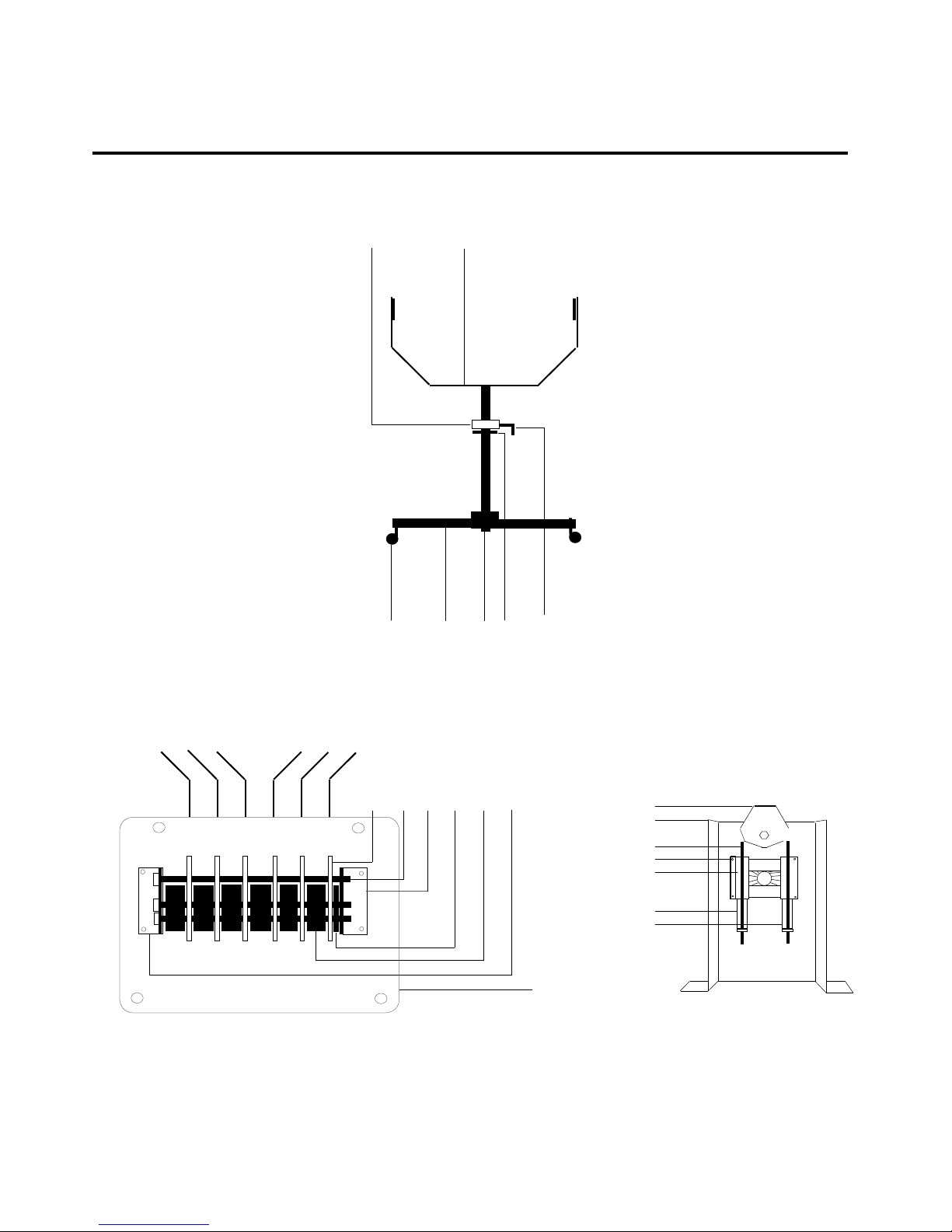
1. Find the cast aluminum base legs. One at a time, with the hollow side facing down,
place three base legs around the bottom of the yoke tube. Note: either end of tube
can be top or bottom. As you place the legs around the tube, simultaneously insert
the hex head bolts into the pass through holes on each of the base leg. Slide on
the lock washer and hand tighten the hex nuts. Using a 1/2" socket, nut driver or
open end wrench. Proceed to alternately tighten each bolt. To prevent gaps be-
tween the legs do not tighten any one bolt completely, tighten bolts equally.
2. Next Insert 3 casters into the base legs. Occasionally the base leg through hole
may accumulate excess powder coating, making it difcult to insert casters. Light
ling with a rattail le can be used to clean excess coating. Slide the height collar
ring onto the yoke tube, followed by the height collar washer. Then insert the yoke
into the base insert tube. Screw in the height collar handle and raise or lower to
desired height and lock handle into place.
3. Slide the small fiber friction washer followed by the sleeve bearing and then the
large friction washers onto the threaded stud of the adjustable tilt handle. Thread
handle into the bail until it is ushed to the yoke weld nut on the other side of the
bail. Spread washers fully apart so that the yoke can be inserted between them.
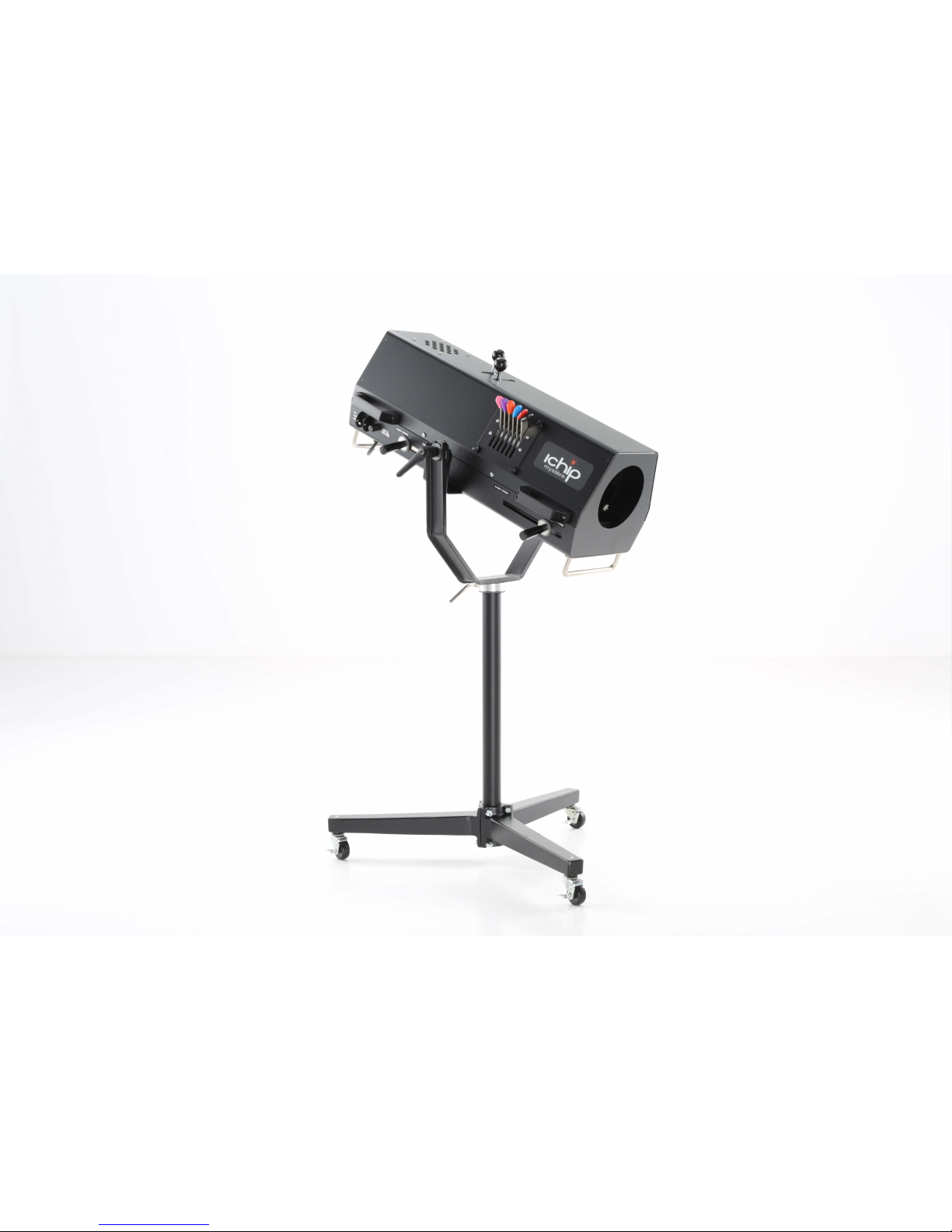
4. Lift the Ichip Mystére using the front and rear black carry Handles located on
both sides of the chassis. Position the bail handle shafts in the U-shaped slots at
the top of the yoke. Ensure that the washers are positioned properly. Turn the tilt
lock handles to tighten the grip on the yoke. Push the button on the tilt handle for
suitable handle positioning.
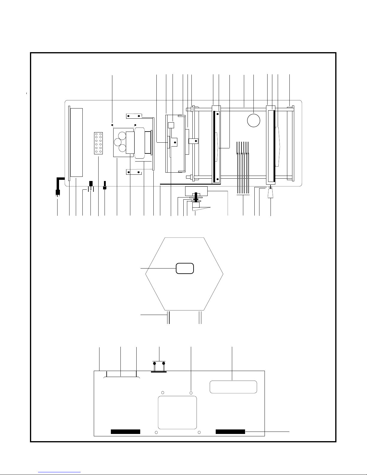
5. The two zinc plated steel control shafts have been threaded on and secured at
the factory, hand tighten the two black control knobs onto the shaft, The Iris and
douser are ready for operation. The shafts have flat cut outs at one end of the
shaft. Use an open end wrench to tighten the shafts securely. A nyloc nut and
washer are supplied to fully secure shaft. Next, unscrew the two 1/4-20 phillips
head shipping screws and washers, remove and save screws for future shipping
use if needed. Slide the metal washer (first) and then the fibre lens washer onto
the threaded stud of the lens handles. Insert and hand tighten to lock down
(clockwise) and loosen to operate (counterclockwise).
6. Lastly, Screw the two black control knobs onto the iris and dowser control shaft
to complete the assembly process. The Ichip Mystére is now ready for
operation.
Ichip Mystére
ICM-150/120 User Manual 3

SYSTEM OPERATION
I. SETUP AND FOCUSING
1. The Ichip Mystére is equipped with a three position switch. On, Cooling & Off. Be
sure that the switch is in the off position (down) before connecting the AC line cord
into a 110-120 VAC Grounded Receptacle. Flip the power switch to the middle fan,
position for cooling purposes. Flip the switch to the on, up position. LED Array will
strike immediately, and will come up to full output.
2. Lamps are not classied as hot-restrike and do not require cool down in order to re-
strike. However, we recommend a 30 second cool down period at the end of
usage.
3. Move iris and dowser controls toward operator to open.
4. Move front lens forward for spot or rearward for ood distribution. Position can be
chalk marked on side of chassis near handle set.
5. Move rear lens until edge of pattern is in focus. Position may be adjusted for hard
or soft edge.
6. Close down the iris by moving its control handle away from the operator.
7. Focused may change slightly with iris closed. Best focus setting is with iris half
open.
8. To “zoom” the lenses to a new position, a coordinated motion of both front and
rear lenses is used. Note that these lens move opposite to each other to maintain
focus
II. BEAM CONTROLS
1. The dowser gradually dims the beam until completely blacked out. Move the control
handle away to close and toward to open the dowser. The dowser Micro switch
cuts down the power to the LED Array when fully closed.
2. The iris provides a 6 to 1 change in image diameter. It is controlled by the front
handle, away to close and toward to open. The brightest spot is obtained with the
iris open and the lenses adjusted for the largest spot desired. Smaller spots are
then obtained using the iris.
Ichip Mystére
ICM-150/120 User Manual 4

TECHNICAL DATA
I. 36 Chip Micro Lens LED Array Module
The Ichip Mystére uses a 5600K, 90 CRI 36 chip Micro lens LED Array Module. The
internally mounted ballast is used to operate the LED Module from standard 120 volts.
The LED array module lifespan is on average of 6000 hours. However at normal use it is
rated well beyond 6000 hrs. Once the LED module reaches the 6000 hour mark, one or
two of the LED Micro chips may expire. However this will not noticeably effect the light
output of the Ichip Mystére, which will continue to operate well past the 6000 hour mark.
CRI (color rendering index) is a measure of how accurately a light source illuminates
objects' true colors. Our LED modules have a CRI value of 90, indicating that the
modules are able to produce white light that approximates halogen or incandescent
lighting and natural daylight. The LED Module is cooled by two specially designed fans to
insure cool and quiet operation. One fan is chassis mounted below the LED module while the
second fan is mounted directly onto LED Module. The fans are essential to lamp
operation. Improper cooling will cause decreased LED module life. Allow LED Module to
cool before cutting power.
II. ELECTRICAL
I. LED Module Replacement Installation
1. Turn off and unplug unit.
2. Remove the eight carry handle mount screws and four housing mount screws
located on both sides of housing.
3. Remove the two black control handle knobs from the control shafts.
4. Lift and remove housing from chassis.
5. Unscrew the four LED module cooling fan button head screws followed by the four
LED module Button head mount screws. For easier access to the LED module
mount screws, The LED module mount bracket may be removed by unscrewing the
four phillips screws located on the underside of the chassis.
6. Replace the LED module and LED module cooling fan by reversing the above
steps
Ichip Mystére
ICM-150/120 User Manual 5
The Ichip Mystére operates on 110 to 120V 50/60Hz A.C. and draws Less than 7 amps.
(replace using 7A 3AB Bussman fuse) Located at the rear inside of the unit you will nd
the internally mounted Ballast used to supply the lamp with the proper voltage and
current. There are no user serviceable parts located on this ballast!! Refer to the
trouble shooting guide located on page 6 of this manual, or contact the local dealer/
representative in your area.
MAINTENANCE

II. LENS CLEANING
1. Slide front lens to its extreme forward position using the control handle.
2. Clean the front lens using glass cleaner and a soft, lint-free cloth. The rear surface
may be reached by removing the housing.
3. Slide rear lens fully back and clean both surfaces.
4. Replace housing.
III. COLOR GEL REPLACEMENT
1. Unscrew four thumbscrews on either side of the color boomerang.
2. Lift boomerang off. Position it upside down, control levers facing you.
3. Raise the lefthand (operator right) gel holder and lower all the others.
4. Remove three clip fasteners around the gel holder rim.
5. Separate rings, remove old gel.
6. Use the ring as a pattern to cut new gel. Darker gels should be put in lefthand
(operator right) gel holders.
7. Insert gel, cover with ring and secure with three clips.
8. Lower lefthand (operator right) gel holder and raise next one.
9. Repeat steps #4 to #8. To access the bottom gel clip, raise all the gels to the left
or right and lower the one being worked on.
10. As you move toward the right-hand gels (operator right), insert progressively
lighter colors. The lefthand (operator right) holders should be used for deep blue
or purple gels.
11. Replace boomerang assembly and secure with four thumbscrews.
IV. LUBRICATION
1. Remove housing carry handles and mount screws.
2. Tighten vertical tilt lock handles on either side of yoke. Unit will be unbalanced
with the housing off
3. Unscrew the two black control knobs leaving the control shafts in place.
4. Grip both the front and rear end of the housing.
5. Lift straight up until front lens is cleared, and remove.
6. Wipe all bearing shafts with a cloth dampened with furniture wax.
7. Operate front and rear lenses forward and back to distribute wax.
8. Replace housing using the black carry handles. Guide front over lens and line
up front housing and chassis.
9. Replace the two black control knobs.
10. Re-assemble the carry handles and chassis mount screws .
V. TROUBLESHOOTING-LAMP AND BALLAST
Lamp does not light:
1. If unit is off, check power and fuse. Replace fuse with 7 amp 3AB fuse.
2. If unit is on and the fan is running, check the following:
(a) Check that the LED module connections are in place and secured. Lamp
may be defective or reached the end of its life.
(b) The power supply contains no user serviceable parts. Contact Phoebus Mfg.
6
Ichip Mystére
ICM-150/120 User Manual

7
Ichip Mystére
3c3d 3e3f3g3h
345-0001
1k
3a
3b
2a 2b 2c 2d 2e 2f 2g 2h 2i 2j 2k 2m 2n 2o 2p 2q2r 2s 2t 2u 2v
1c 1d 1e 1f 1g 1m 1n 1o 1p
1h 1i 1j 1l
1a
PARTS LAYOUT (CHASSIS AND HOUSING)
Ichip Mystére
ICM-150/120 User Manual
3i
2l
1b

8
6a
6b
6c
6d
6e
6f
6g
4a 4b
4c 4d 4e 4f 4g
5a 5b 5c 5d 5e 5f
5g 5h 5i 5j 5k 5l
Ichip Mystére
ICM-150/120 User Manual
PARTS LAYOUT (BASE, COLORBOOM & DOUSER ASSEMBLIES)
5j

Retail Replacement Parts List
1a. Lamp Fan Guard
1b.
Douser Bracket
1c.
Dimmer Switch
1d.
Iris Bracket
1e.
Iris
1f.
Shaft Collar
1g.
Rear Lens Block
1h.
Rear Lens Bracket
1i.
Rear Lens
1j.
Lens Rail Rod
1k.
Air Vent Screen
1l.
Front Lens Block
1m.
Front Lens Bracket
1n.
Front Lens
1o.
Lens Rail Bracket
Ichip Mystére
ICM-150/120 User Manual 9
2a. Line Cord 1
2b.
3a.
#Description Price #Description
Part Number
ICM-SG31B
ICM-007
PER
1$10.00
1$75.00
ICM-V71C1 1$25.00
ICM-008 1$80.00
Swivel Bushing ICM-771-56 1$17.50
ICM-101 1$165.00
ICM-6S 2 $7.00
ICM-011R 1$100.00
ICM-009 1$75.00
ICM-105X140 1$85.00
ICM-SS38R 2$50.00
1p.
ICM-SC80B 1$10.00
ICM-011F 1$100.00
ICM-010 1$75.00
ICM-6X16 1$85.00
ICM-021 2$80.00
ICM-MR31 $28.00
Part Number
Driver Mount Brkt. ICM-002
PER Price
1$48.00
2c. LED Driver ICM-HGL36B 1$115.00
2d. Switch Guard ICM-771-75 1$18.00
2e. 3 Position Switch ICM-2GG51 1$28.00
2f. Terminal Block ICM-0625220 1$22.00
2g. Fuse Holder ICM-3424X 1$22.00
2h.Chassis Mount LED Fan ICM-0A92A 1$50.00
2i. LED Mount Fan ICM-UF80B 1$45.00
2j. LED Array Module ICM-56K90C 1$600.00
2k. LED Module Bracket ICM-001 1$98.00
2l. Rear Lens Brake Arm ICM-023 1$25.00
2m. Douser Swivel ICM-019 1$60.00
2n. Med. Brake Washer ICM-771-84 2$7.00
2o.Yoke Sleeve Bearing ICM-6391K 2$4.75
2p. Sm. Brake Washer ICM-771-83 2$4.75
2q. Yoke Tilt Handles ICM-DB12 2$40.00
2r. Medium Duty Bail ICM-011 1$115.00
2s. Color Boom Assembly ICM-015A 1$425.00
2t. Fibre Lens Handle washer ICM-771-83L 2$4.75
2u. Steel Lens Washer ICM-1420 2$1.00
2v. Lens Control Handle ICM-5K51 2$15.00
Serial Number Plate ICM-ICMSP 1$12.00
3b. Chassis Guide Handle ICM-014 2$100.00
3c.Housing ICM-001 1$300.00
3d.Light Baffle ICM-018 1$36.00
3e.Light Baffle Spacer $20.00
ICM-163214 1
3f.D.C. Control Handle w/knob ICM-163214 1$30.00
3g.Color Boom Thumbscrew ICM-B1032 4$3.00
3h.Housing Product Label ICM-ICD3C 1$10.00
3i.Housing Carry Handle ICM-F14 4$60.00
4a.Height Collar ICM-0055 1$60.00
4b.Medium Duty Yoke ICM-0033 1$300.00
4c.Caster w/Brakes ICM-0033 3$25.00
4d.Cast Aluminum Base Leg ICM-0054 3$225.00
4e.Yoke Insert Tube ICM-0056 1$40.00
4f.Height Collar Washer ICM-0D25 1$7.00
4f.Height Collar Handle ICM-82571 1$18.00
5a.Gel Frame 15º Right
Gel Frame 30º Right
Gel Frame 45º Right
5b.
5c.
5d.Gel Frame 45º Left
Gel Frame 30º Left
5e.
Gel Frame 15º Left
5f.
5g.Gel Frame Color Ring
5h.Boom Retaining Bolt
Left Boom Bracket
5i.
Boom Thrust Washer .187
5j.
Boom Thrust Washer .375
5k.
5l.Boom Bracket Right
5m.Color Boom Plate
6a.Douser Swivel
Douser Bracket
6b.
Douser Connecting Rod
6c.
Douser Spacer Bar
6d.
6e.Douser Slide Retainer
6f.
6g.
Upper Douser Jaw
Lower Douser Jaw
ICM-017-1R
ICM-017-2R
ICM-017-3R
ICM-017-4L
ICM-017-5L
ICM-017-6L
ICM-UQ0001
ICM-1420HXB
ICM-016L
ICM-030-1
ICM-030-3
ICM-016R
ICM-015
1
1
1
1
1
1
6
3
1
2
5
1
1
ICM-019
ICM-007
ICM-771-151
ICM-82571
ICM-82571
ICM-82571
ICM-82571
1
1
2
2
2
1
1
$22.00
$22.00
$22.00
$22.00
$22.00
$22.00
$60.00
$5.00
$45.00
$10.00
$45.00
$45.00
$60.00
$48.00
$75.00
$24.00
$12.00
$12.00
$32.00
$32.00

Ichip Mystére
ICM-150/120 User Manual 10
Replacement Parts Price List
Prices subject to change without notice
Stock Description Set List Stock Description Set List
#Internal and External Parts #$#Electrical Parts #$
IM-001 Housing 1 225.00 IM-040 Ballast 1 750.00
IM-002 Chassis 1 175.00 IM-041 SMR-202/D1 Lamp 1 350.00
IM-003 Lamp Bracket 1 55.00 IM-042 SMR-202/UV1 Lamp 1 450.00
IM-004 Lamp Mount Plate 1 35.00 IM-043 Fuse 5 32.00
IM-005 Ballast Bracket 1 35.00 IM-044 Fuse Holder 1 9.00
IM-006 Field Lens Bracket 1 35.00 IM-045 Lamp Fan 1 25.00
IM-007 Dowser Bracket 1 40.00 IM-046 Gel Fan 1 25.00
IM-008 Iris Bracket 1 35.00 IM-047 Terminal Block 1 10.00
IM-009 Rear Lens Bracket 1 18.00 IM-048 Switch 1 18.00
IM-010 Front Lens Bracket 1 18.00 IM-049 Line Cord 1 25.00
IM-011 Lens Block set 2 65.00 Base and Stand Parts
IM-012 Lamp Fan Bracket 1 18.00 IM-050 Bail 1 35.00
IM-013 Gel Fan Bracket 1 18.00 IM-051 Medium Duty Yoke 1 75.00
IM-014 Handle Set w/ Seats 2 32.00 IM-052 Base Leg Set 3 105.00
IM-015 Boom Plate 1 18.00 IM-053 Caster w/Brake Set 3 54.00
IM-016 Boom Bracket Set 2 15.00 IM-054 Height Collar 1 18.00
IM-017 Color Frame Set 6 72.00 IM-055 Height Collar Handle 1 12.00
IM-018 Light Bafe 1 12.00 IM-056 Base Insert Tube 1 35.00
IM-019 Dowser Swivel 1 15.00 Optical
IM-020 Iris Mount Assemb. 1 165.00 IM-060 Front Lens 1 85.00
IM-021 Rail Bracket Set 2 18.00 IM-061 Rear Lens 1 75.00
IM-022 Lens Rod Set w/Clips 2 12.00 IM-063 Aspheric Lens 1 45.00
IM-023 Rear Brake Arm 1 12.00 IM-064 Field Lens 1 35.00
IM-024 Ballast Tray 1 18.00 Part Kits
IM-025 Rear Access Door 1 15.00 IM-070 Lens Handle Kit 1 15.00
IM-026 Access Door Frame 1 12.00 IM-071 Fiber Washer Kit 1 9.00
IM-027 Dowser Jaw Set 1 18.00 IM-072 Label Kit 1 18.00
IM-028 Lamp Adjustment Plate 1 22.00 IM-073 Adjustable Tilt Handle Kit 1 50.00
IM-029 Lamp Index Ring 1 12.00 IM-074 Thumbscrew Kit 1 12.00
IM-030 Boom Thrust Washer set 7 14.00 IM-075 Switch Guard Kit 1 9.00
IM-031 Lamp Bracket Hinge 1 8.00 IM-076 Control Handle Kit 1
IM-032 Rear Door Hinge 1 8.00 IM-077 Connecting Rod Kit 1
IM-078 Retainer spacer bar Kit 1 22.00
IM-078 Knurled Thumbscrew Kit 1 15.00
WARRANTY CARD
MODEL NUMBER
SERIAL NUMBER
DATE OF PURCHASE
PLACE OF PURCHASE (DEALER NAME)
USER’S NAME
COMPANY NAME
STREET ADDRESS
CITY STATE ZIP
TELEPHONE FAX EMAIL
Please fold along the dotted lines and staple
with return address on the outside as shown above.
Thank you!
PHOEBUS MANUFACTURING
1029 Washington St.
San Carlos, CA. 94070
ATTENTION: WARRANTY DEPARTMENT
Place
stamp
here
This manual suits for next models
1
Table of contents