Phoenix Pro-V Series User manual

1
Pro-V Series
Programmable Digital Thermostats
With Modulating FAN control
OPERATION MANUAL
Index
Content Page
INSTALLATION........................................................................................................3
MOUNTING ON ELECTRIC BOX ..............................................................................3
MOUNTING FRONT COVER....................................................................................3
WIRING EXAMPLE...............................................................................................3
OPERATION...........................................................................................................4
SETTING CLOCK………………………………………………………………………. 7
SETTING PROGRAM FUNCTION ………………………………………………………. 7
Phoenix Manufacturing Inc.
3655 E. Roeser Rd. – Phoenix, AZ 85040
01-999-2578
Mode of Operation
Fan Speed
Temperature Set
Set Time, Date, Schedules
On / Off

2
Front view Back view
#
Item
Description
1
LCD
Display temperature and working status.
2
MODE button
Access to user and engineer menu and for setting
confirmation or change
℃
/
℉
unit if press for over 3 sec.
3
FAN button
Toggle to change Fan mode: Auto or cont. Low/ Hi
4
UP & DOWN buttons
Increase & decrease setting or previous/next item
5
SET button
Setting for schedules and Timers
6
On/Off button
Turn on/ off thermostat
7
Set-point icons
Displaying set-point temperature while it is flashing
8
Fan icons
Indicate Fan status
9
Snow Flake icon
Indicate working on Cooling mode; Flashing = Pre-wet
10
Hot spring icon
Indicate working on Heating mode (NA)
11
Flow icon
Indicate working on ventilating mode
12
Gear icon
Indicate cooler is ON
13
Clock
Indicate current System ON or OFF was enabled by real
time Timer.
14
Sleep
(NA)
15
Moon Sign
Indicating room is unoccupied or Vacation Mode
16
Outdoor icon
Indicating door/ window is open(NA)
17
Cover screw
Screw to tighten back cover with front cover
18
Back plate
Plate for mounting on electric box
19
Wiring terminal blocks
Terminals for wiring
20
Mounting holes
Holes for mounting on electric box
21
Clock
Display time
22
Schedule number
Current Schedule running or setting
23
Day
Current day of Sunday ~ Saturday or setting
24
Sun
Indicate Drain is undergoing now

3
Installation
Note: This unit requires at least 6 conductor thermostat wire. 18-6 is recommended.
Mounting on electric box
1. Separate back plate from the controller by loosing the cover screw;
2. Align the mounting holes on the screw holes of the electric box(applicable to 65x65 or US standard box);
3. Fix the back plate on the electric box by tightening the back plate screws. Suggest using Philips drive “truss
head” or “washer head” #6-32x 3/4” (20mm).
4. DO NOT let the bolt head rise above the wall of mounting holes of back plate. It might cause the short circuit
of the controller.
Mounting front cover
1. Lock front cover on the back plate by tightening the cover screw underneath with Philips head screw driver.
Wiring Example
All wires coming from electric
box must be inserted above
the retainers of respective
terminal block before tightening
the captive screws

4
Operation
User Mode Operation
The first tier of operation includes the following settings as Figure 2. To operate:
1. Power switch “ON” or “OFF” to start/ stop the System;
2. After switching “ON”, press any button to start the User Mode operation.
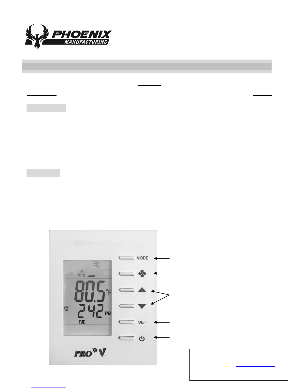
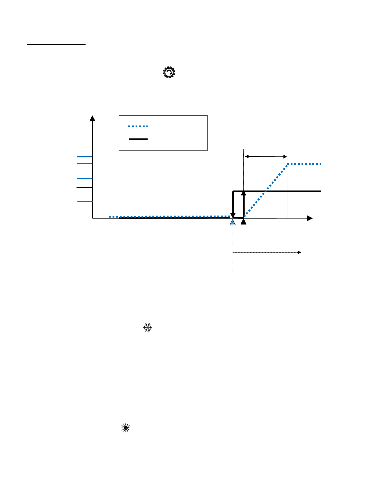
i. Press “MODE” button to switch over different working modes. When MODE is pressed for more than 3
seconds, the unit of temperature will toggle to change to ℉or ℃.
ii. Press UP/ DOWN button to increase/ decrease or rotate the values of setting.
iii. Press “FAN” button to toggle over different fan modes. When FAN is pressed for more than 3 seconds, it
will activate “DRAIN” command to start drain pump for 1 1/2 minutes.
iv. Press “SET” button to set current time-date and timer. When SET is pressed for more than 3 seconds,
users can set the set points schedules.
3. It will return to normal display with the latest setting if there’s no button pressed for 10 seconds.
#
Item
Description
Remarks
1
Normal Display
Display current room or set-point
temperature and current time-day.
Setting “-SP-“parameter in
Engineer table to choose Current
room or Set-point temperature.
2
Temperature Setting
Set the required temperature
3
Mode Select
1. Select the working mode:
(1) CooL/ AirC for Cooling or
Ventilating.
(2) run/ Ovrd/ HAnd for schedule
2. When MODE is pressed for more
than 3 seconds, the unit of
temperature will toggle to change to
℉or ℃.
RUN means Running Schedules.
Ovrd (override) means
temporarily using manual S.P and
skip “current” Schedule.
HAnd means using manual S.P
instead of “all” Schedules.
4
Fan Auto/ Continuous
1. Change Fan mode for Auto speed
or manual Low/ Hi speed.
2. When FAN is pressed for more
than 3 seconds, it will activate
“DRAIN” command to start drain
pump for 1.5 minutes.
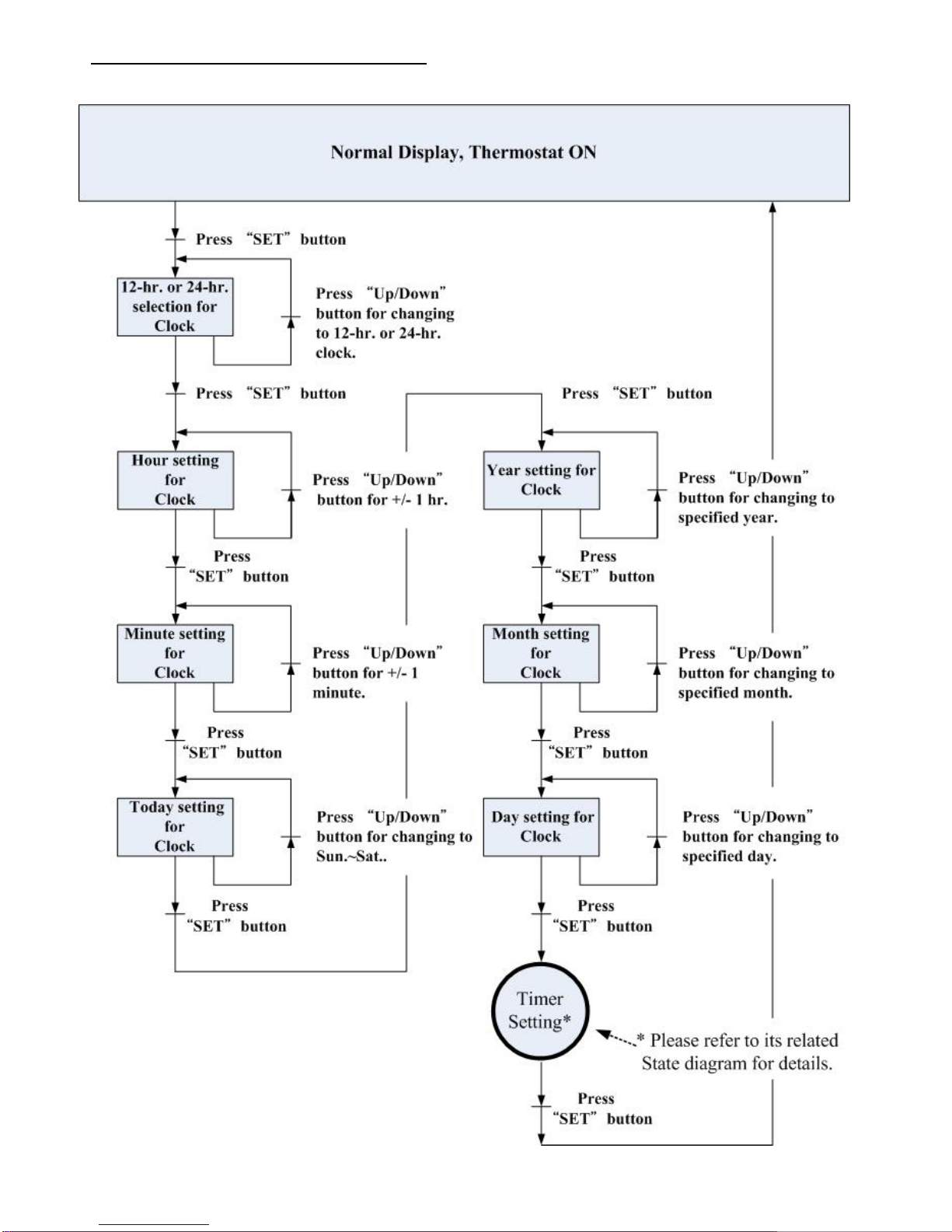
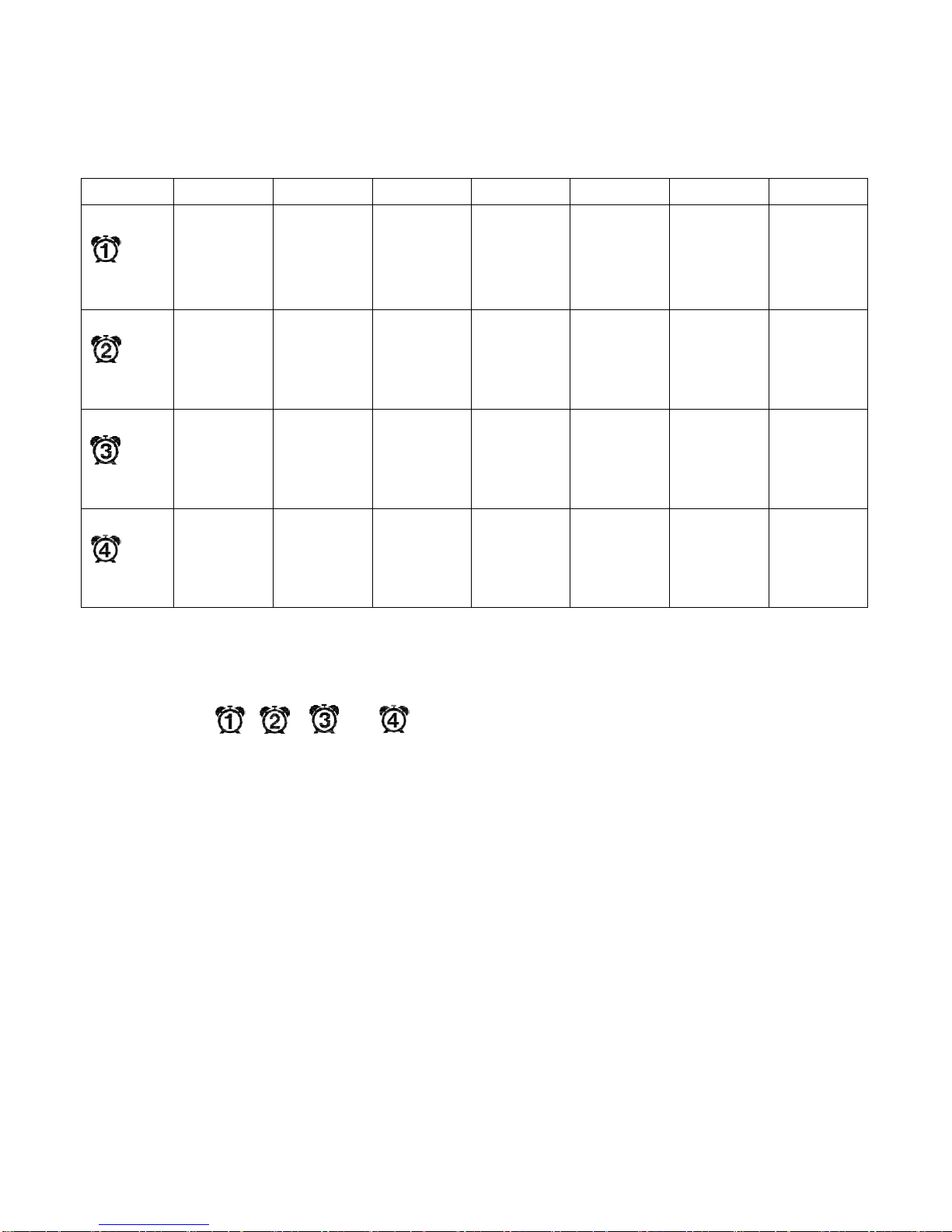
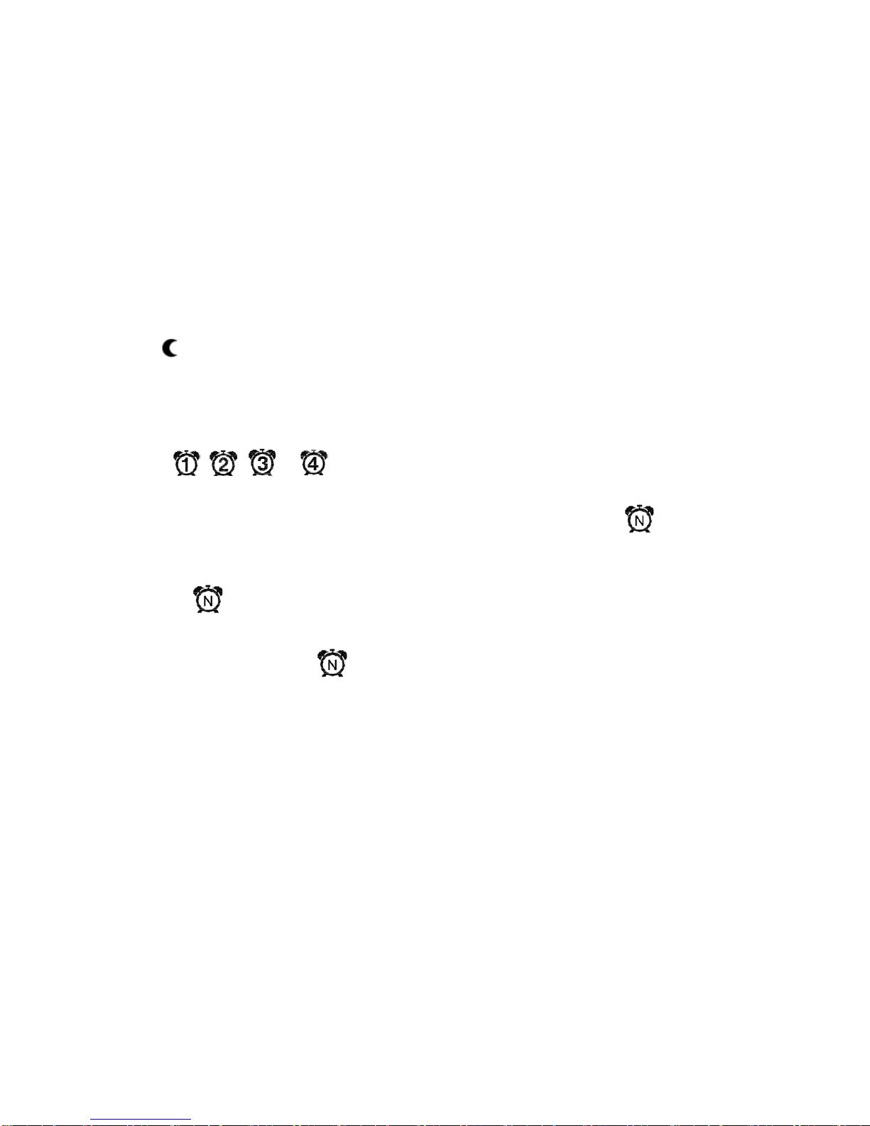
5
Time/ Date/
Schedule Setting
SET
1. Set current time in 12- or 24-
hour format;
2. Set calendar and day of week;
3. When SET is pressed for more
than seconds, users can set
temperature set points schedules
Press SET to continue settings.
Press MODE, FAN, or POWER
button to escape any time during
setting.

5
Fig. 2 User Mode operation sequence

6
1. Detailed State Diagram for Clock Setting

7
2. Detailed State Diagram for Schedule Setting
- Press “Mode” button to
select (day shows steadily) /
deselect (day flash).
- Press Up/Down button to
other day for multiple choice.

8
Example of Setting Table for Schedules
Table of Set-point temperature for each Schedule will be like this (Ex.: if wants 6:00 79.0℉, 8:00 85.0℉,
18:00 79.0℉, and 22:00 79.0℉every day):
Sun
Mon
Tue
Wed
Thu
Fri
Sat
Sch. 1
6:00
Cool:79.0℉
/ 26.0℃
6:00
Cool:79.0℉
/ 26.0℃
6:00
Cool:79.0℉
/ 26.0℃
6:00
Cool:79.0℉
/ 26.0℃
6:00
Cool:79.0℉
/ 26.0℃
6:00
Cool:79.0℉
/ 26.0℃
6:00
Cool:79.0℉
/ 26.0℃
Sch. 2
8:00
Cool:85.0℉
/ 29.5℃
8:00
Cool:85.0℉
/ 29.5℃
8:00
Cool:85.0℉
/ 29.5℃
8:00
Cool:85.0℉
/ 29.5℃
8:00
Cool:85.0℉
/ 29.5℃
8:00
Cool:85.0℉
/ 29.5℃
8:00
Cool:85.0℉
/ 29.5℃
Sch. 3
18:00
Cool:79.0℉
/ 26.0℃
18:00
Cool:79.0℉
/ 26.0℃
18:00
Cool:79.0℉
/ 26.0℃
18:00
Cool:79.0℉
/ 26.0℃
18:00
Cool:79.0℉
/ 26.0℃
18:00
Cool:79.0℉
/ 26.0℃
18:00
Cool:79.0℉
/ 26.0℃
Sch. 4
22:00
Cool:79.0℉
/ 26.0℃
22:00
Cool:79.0℉
/ 26.0℃
22:00
Cool:79.0℉
/ 26.0℃
22:00
Cool:79.0℉
/ 26.0℃
22:00
Cool:79.0℉
/ 26.0℃
22:00
Cool:79.0℉
/ 26.0℃
22:00
Cool:79.0℉
/ 26.0℃
Note: If set a Schedule’s time as “--:--“ instead of a specified time, it means disable this Schedule.
P.S.: The icon , , , or will be shown on LCD steadily while the
Schedule 1,2,3, or 4 is running.

9
Control Action
1. Cooler and Fan Controls:
When cooler is on, a “Running ( Gear) ( )” icon will be shown on the LCD.
2. Pre-wet Action:
Pre-Wet will happen when the cooler pump is off for 10 minutes or more and call for cooling as the above control
diagram.--- If need to do Pre-wet, when the room/space temperature reach SP or above, the cooler pump will be on
for 1 minute only (i.e. no Fan). This action is called Pre-wet. And after Pre-wet finish, the Fan will return back to
appropriate speed.
During Pre-wet period, the icon of ice flake will flash to indicate pre-wetting is in action.
Pre-wet might be postponed until drain action finished.
3. Drain Action:
(1) Automatic Drain: Every accumulative 4 hours(default and 2, 4, 6, 8, or 0(OFF) hours selectable) of cooler pump
operation will start drain pump for 2 minutes(default, and 2, 5 or 9 minutes selectable).
(2) Manual Drain: Press FAN push button for more than 3 seconds will command drain pump to activate for 1.5
minutes. It will reset the timed circulating cooler pump operation counter. This can be done even at system OFF but
not executed during Pre-wet period.
During dwell time, the icon of SUN will be shown to indicate drain is in action.
Current
Temperature
Cooler On
SP
Fan Control for Cooling Mode
OFF
100%
SP – Diff.
ON
Fan Output
Cooler Output
Proportional
Band
Fan High
Fan Med
Fan Low
0%

10
4. Fan Controls:
(1) Vent Mode: Press FAN push button to set AUTO/ LOW/ MED/ HIGH fan speed. The respective modulating
output can be set for each manual speed.
(2) Cool Mode: Press FAN push button to set AUTO/ LOW/ MED/ HIGH fan speed. The respective modulating
output can be set for each manual speed.
(3) For Auto fan speed, Low/ Med/ High fan bar will appear when fan speed reaches the set output respectively.
Special:
1. ESI (Energy Saving Input) Contact status -- When the contact is activated (Vacation or Room unoccupied), a
“Moon ( )” icon will be shown on the LCD and the thermostat will change the set-point temperatures of
Cooling & Heating to be ESIC & ESIH (refer to Engineer table for details.). When the contact is deactivated
(Room back to be occupied), it will set the set-point values back as normal.
2. If disable local ESI contact detection, the room will become always occupied status as default.
3. The icon , , , or will be shown on LCD while the Schedule 1,2,3, or 4 is running or being set.
4. If press “MODE” button, there are three schedule modes “RUN, Ovrd, and HAnd” for selection.
a.) RUN mode means Running on Schedules. And at the same time, an icon ( ) will be steadily shown
on the LCD.
b.) Ovrd (override) mode means temporarily using manual S.P instead of “current” Schedule. And the
icon ( ) will be flashing on the LCD.
c.) HAnd mode means using manual S.P instead of “all” Schedules. i.e. Temporarily disable all
schedules. And the icon ( ) will be NOT shown on the LCD.
Table of contents
Popular Thermostat manuals by other brands

hager
hager 25113 quick start guide

KING
KING H30 Series instructions

BEINAT
BEINAT LC100 quick start guide

HaiLin Controls
HaiLin Controls A2203 Installation and operating instructions

EPH Controls
EPH Controls HDT Installation and operation guide

Robertshaw
Robertshaw RS3110 SERIES User and installation manual

White Rodgers
White Rodgers 1F90-71 Operation guide

Roth
Roth EnergyLogic Touchline 230 V Guidelines for the electrician

ClimateMaster
ClimateMaster iGate AWC99U01 Installation operation & maintenance

Polypipe
Polypipe UFHTFTM user manual

Honeywell
Honeywell Tradeline T8611M installation instructions

Garrison
Garrison 043-6080-0 instruction manual