1
WiFi 2.4G Adapter
WiFi 2.4G RJ45 A
WiFi 2.4G DB9 B
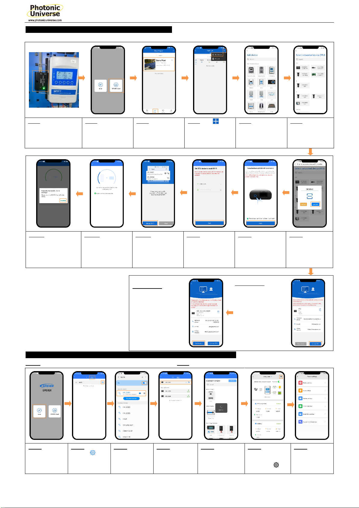
1. Overview
Through a local WiFi 2.4G network, the WiFi 2.4G adapter can transmit
all operational data from the solar controller, inverter, or inverter/charger
to the cloud server in real-time. Users can remotely monitor the
connected devices and program parameters via the server, mobile APP,
or the large screen.
Features:
Applicable to controllers, inverters, or inverter/charger with RJ45, DB9
interfaces
Use immediately after connecting; easy and convenient operation
Directly powered by the communication port
Up to 30 meters of communication distance
Support the “Local” and “Cloud” working mode.
One key to restoring the factory settings
2. Appearance
2.1 WiFi 2.4G RJ45 A
Interface instruction
Connect to the solar controller, inverter, or
inverter/charger
One key to restoring factory settings
Note: Long press the Reload button with a
sharp object when the terminal’s power is on.
The Link indicator flashes twice quickly, and
the factory settings are restored.
Indicate the communication status
Indicate the power status
Reset to the factory mode
2.2 WiFi 2.4G DB9 B
Interface instruction
Connect to the solar controller, inverter, or
inverter/charger
Enhance the signal transmission
One key to restoring factory settings
Note: Long press the Reset button through
the KEY hole with a sharp object when the
terminal’s power is on. The indicator light
flashes twice quickly, and the factory
settings are restored.
Indicate the communication status
(Observe the indicator status through the
KEY hole)
Indicate the power status
Connect the WiFi 2.4G DB9 B to the solar controller, inverter, or
inverter/charger by a DB-9 female connector. The wire sequence and
name of the DB9 female connector are shown below.
Reset to the factory mode
Peak emission: 5V@100mA; Idle: 5V@40mA
general communication standardV1-1.0
IoT communication protocol V1.1
4. Disclaimers
The warranty does not apply to the following conditions:
Damage caused by improper use or inappropriate environment.
The parameter setting exceeds the WiFi terminal’s limit.
Damage caused by working temperature exceeds the rated range.
Unauthorized dismantles or attempted repairs.
Damage caused by force majeure.
Damage occurred during transportation or handling.
※Thanks for selecting the WiFi transmission terminal; please
read this manual carefully before using the product.
※Please keep this manual for future reference.