5.2 Wake up
1. Pressing "Set" or " " or "Back" will wake up
2. Pressing "Backlight" key will wake up the remote
programmer and also turn on the LCD backlight
3. Pressing the "Light" key to wake up the remote
programmer will also turn on the light.
5.3 Parameter setting
Press " " to browse the setting parameters. When
you want to modify the highlighted parameter, press
the "Set" key and the cursor will start blinking. Press
the " " keys to adjust the blinking parameter. After
adjustment is completer, press "Set" to move on to the
next parameter or "Back" to return to the list. For
details, please refer to 7. Parameter setting.
5.4 Send
When the parameters are set up, aim the top of the
programmer at the charge controller and press the
"Send" key. If sent successfully, the programmer will
display "Send Successful" and emit a long beep. If
failed, the programmer will display "Send Failure" and
beep three short sounds.
If the parameters (such as battery type, load current or
voltage settings) are invalid for this controller type, the
programmer will display "Data Error" and beeps three
short sounds.
Note: do not move the programmer during
sending, or the setup will fail.
5.5 Test
Aim the programmer at the charge controller and press
"Test". The load will turn on. Pressing "Test" again will
switch the load to 50% power. Test mode will last for 1
minute before normal operation resumes.
Note: this feature may vary for different
controllers, please refer to the charge controller user
manual.
5.6 Transport mode
Press and hold the "Back" and "Backlight" key for 3s.
The programmer will beep two short sounds. The upper
left of the menu will change from "Setting" to
"Transport".
For the lithium series controller, press the "Test" key;
the remote will show "Transport OK" and emit a long
beep as the controller enters transport mode. If the
remote control shows "Transport Error" and beeps
three short sounds then the controller has not entered
transport mode.
To exit transport mode, press and hold the
"Back" and "Backlight" key for 3s. Please refer to the
solar controller user manual for details.
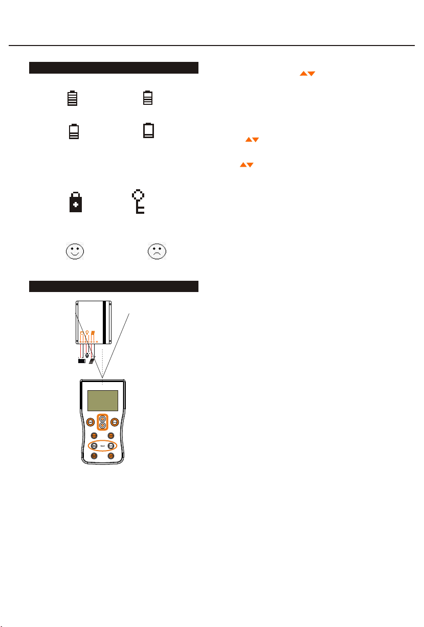
4. Icon description
4.1 Battery capacity indicator
Capacity≥75% 50%≤Capacity<75%
25%≤Capacity<50% Capacity<25%
Key lock Key unlock
4.3 Communication success and failure
Communication success Communication failure
Capacity indicator flashes at <25% to remind the user to
replace the battery.
4.2 Key lock and unlock
5. Operation
5.1 Precautions
Install two AA batteries, positive and negative poles
must not be reversed
The remote programmer will automatically enter
sleep mode after 1 minute with no operation
The remote controller sets solar controllers one at a
time and should not be used with more than one
controller
Using the light or backlight will shorten the battery
life.
Replace the battery when it is low
Remove the battery if the programmer will be
inactive for long periods
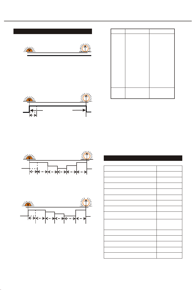
45°
④⑥
③⑤
②
①
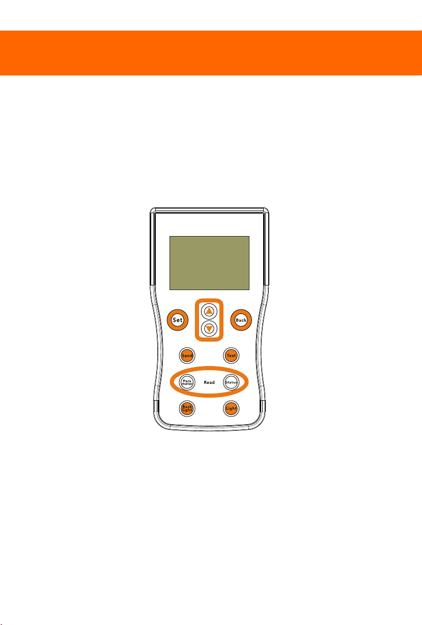
Smart Remote Programmer LUX-PRG User Manual
the remote programmer.