manuals.online logo
Brands
  1. Home
  2. •
  3. Brands
  4. •
  5. PHYWE
  6. •
  7. Power Supply
  8. •
  9. PHYWE 13533-93 User manual

PHYWE 13533-93 User manual

1
www.phywe.com, © All rights reserved 13533-93 / 0416
Operating instructions
Power Supply with Rectifier
14 V AC / 12 V DC, 5 A
13533-93
PHYWE Systeme GmbH & Co. KG
Robert-Bosch-Breite 10
37079 Göttingen
Germany
Phone +49 (0) 551 604–0
Fax +49 (0) 551 604–107
E-mail [email protected]
Internet www.phywe.com
The unit complies
with the applicable
EC-Guidelines
Fig. 1: Front view of the Power Supply with Rectifier 13533-93
1
2
3
4
5
TABLE OF CONTENTS
1SAFETY PRECAUTIONS
2PURPOSE AND CHARACTERISTICS
3FUNCTIONAL AND OPERATING ELEMENTS
4NOTES ON OPERATION
5 HANDLING
6TECHNICAL DATA
7PARTS SUPPLIED
8ACCESSORIES
9WARRANTY
10 WASTE DISPOSAL
1 SAFETY PRECAUTIONS
Carefully read these operating instructions completely
before operating this instrument. This is necessary to
avoid damage to it, as well as for user-safety.
Check that your mains supply voltage corresponds to
that given on the type plate fixed to the instrument.
Install the instrument so that the on/off switch and the
mains connecting plug are easily accessible. Do not
cover the ventilation slits.
Take care that no liquids or objects enter in through the
ventilation slots.
Only use the instrument in dry rooms in which there is no
risk of explosion.
Do not operate if there are visible signs of damage to the
unit or the connection cord.
Only use the instrument for the purpose for which it is
intended.
2 PURPOSE AND CHARACTERISTICS
This robust and practical isolating transformer (Fig. 1) is par-
ticularly suitable as a power supply for student experiments.
The output voltages are in the low voltage extent of protec-
tion. The instrument supplies both an alternating voltage of
up to 14 V, which is selectable in seven equal steps of 2 V,
and a direct voltage that is obtained by bridge rectification.
The direct voltages are about 2 V lower than the alternating
voltages, because of the threshold voltage of the rectifier di-
ode. The voltages are also dependent on the load (see the
diagrams in Figs. 3 and 4).
3 FUNCTIONAL AND OPERATING ELEMENTS
The unit is accommodated in an impact resistant plastic
housing. A retractable carrying handle is recessed into the
unit and can be folded down so that the instrument slopes
down towards the back. Four rubber feet provide resistance
to slipping. The unit can be stacked onto other units of the
same design, because the rubber feet fit into cup-shaped re-
Attention!
2
www.phywe.com, © All rights reserved 13533-93 / 0416
cesses of the unit beneath, ensuring that the top instrument
does not slide off. The sloped position can only be used for
the uppermost unit of the stack.
The supplied connecting cord is used to connect the unit to
the AC mains. The cord is inserted into the equipment con-
nector at the back of the unit. The mains switch for operating
the unit is situated in the immediate vicinity of the equipment
connecting plug at the back of the unit.
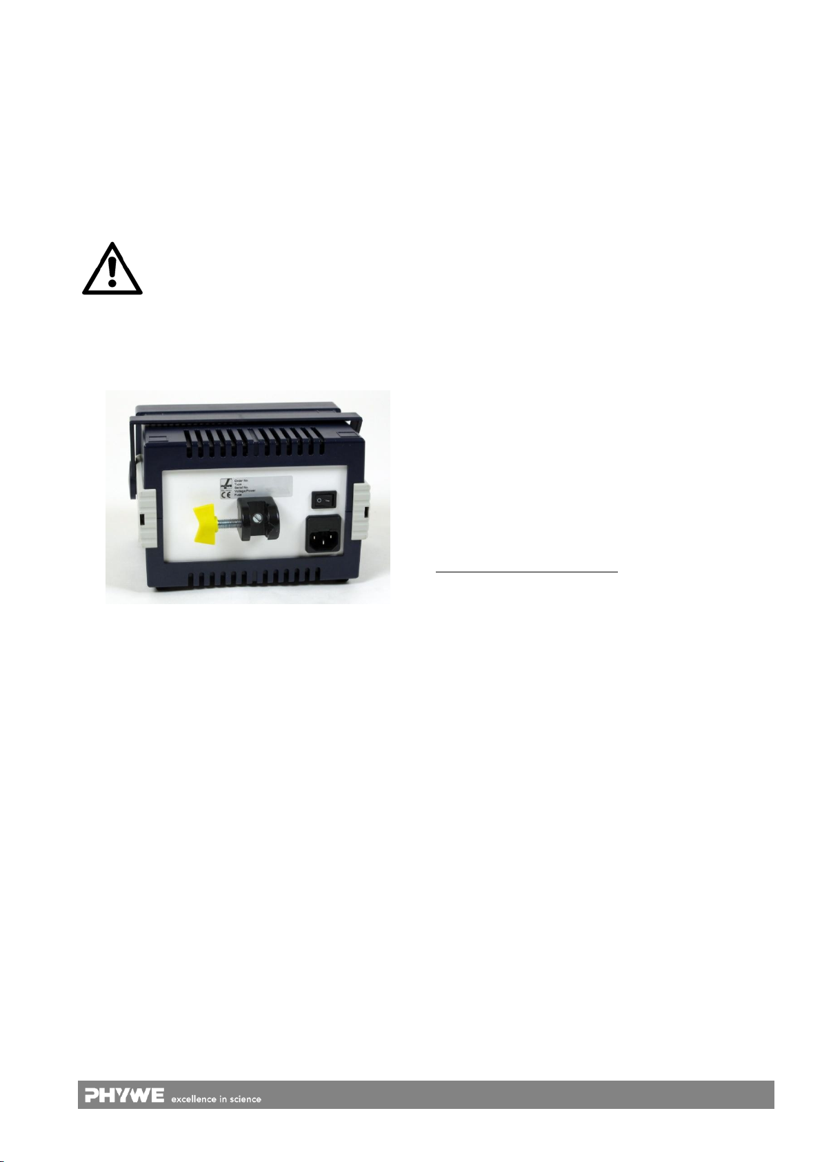
The centre of the back plane provides a thread for the at-
tachment of the support clamp for small case (02043-10),
which is optional available (see Fig. 2). By use of that clamp,
the unit can be fixed to various support rods. Thereby, the
visibility will be increased in demonstration experiments.
To avoid damage to the inner electrical components of the
unit and to prevent people from getting harmed by electric
shock, use the provided support clamp 02043-10, only.
You must not use screws with lengths over 16 mm!
Fig. 2: Back plane of a device in the small case with support clamp
attached.
All other functional and operating elements are located on the
front panel of the unit (see Fig. 1:):
1 Power
On/Off indicator light.
2 Socket ring
For selection of the voltage step at output (3) for the alternat-
ing voltage tapped and at output (4) for the direct voltage
tapped. The selection is made by plugging a special short-
circuiting plug into the central socket and the appropriate
socket in the ring.
3 Output, 2…12 VDC / max. 5 A
Pair of 4 mm sockets for the tapping of a direct voltage; the se-
lection of the size of the voltage is made by means of the
socket ring (2).
4 Output 2…14 VAC / max. 5 A
Pair of 4 mm sockets for the tapping of an alternating voltage;
the selection of the size of the voltage is made by means of the
socket ring (2).
5 Overload circuit breaker
With thermal triggering for protection of both voltage outputs.
4 NOTES ON OPERATION
This high-quality instrument fulfils all of the technical re-
quirements that are compiled in current EC guidelines. The
characteristics of this product qualify it for the CE mark.
This instrument is only to be put into operation under special-
ist supervision in a controlled electromagnetic environment in
research, educational and training facilities (schools, universi-
ties, institutes and laboratories).
5 HANDLING
Two separate outputs (AC/DC) are available in the form of
4 mm safety sockets. They can be simultaneously used.
Each output can be individually loaded up to 5 A: When they
are both under load simultaneously, the total load capacity is
75 VA.
Direct voltage output sockets are not to be connected to al-
ternating voltage output sockets, as the two types of output
are not galvanically isolated from each other.
All outputs are galvanically isolated from the mains, un-
grounded and safeguarded by a circuit breaker. The primary
side of the instrument is additionally protected by a G fuse
element.
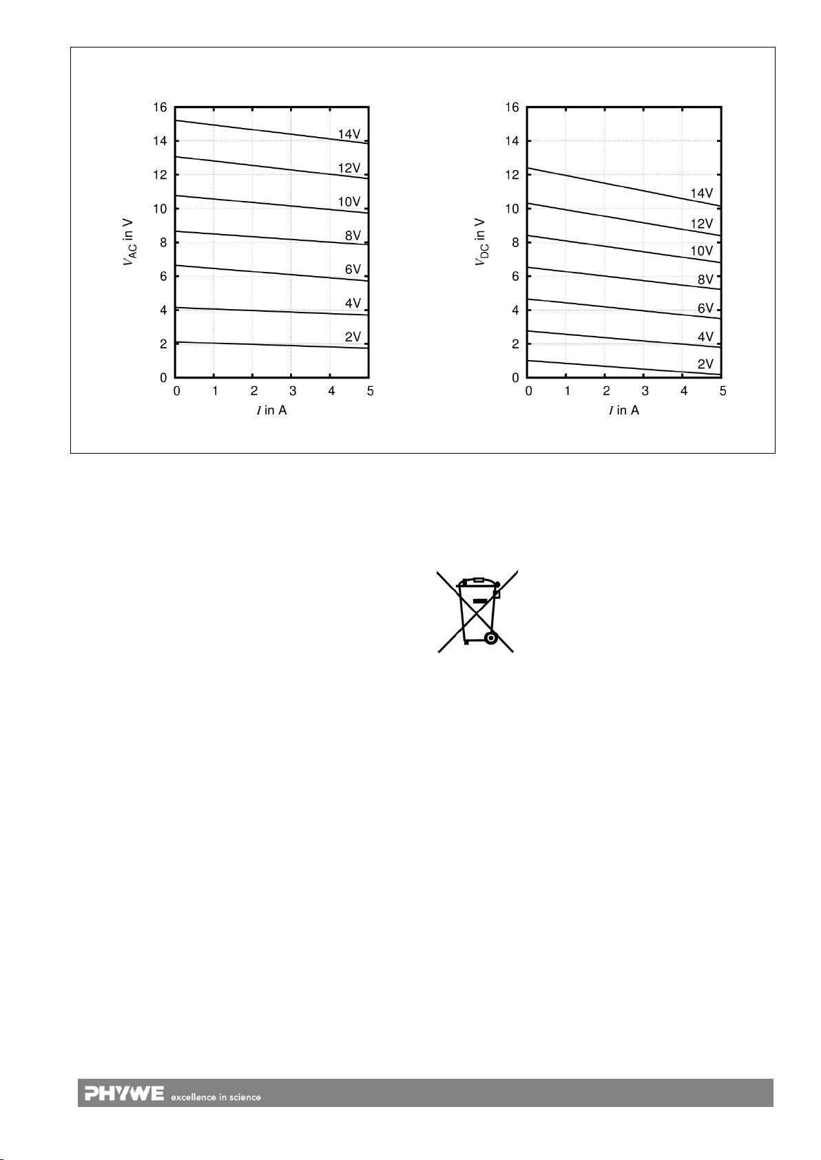
The output voltages are dependent on the load. The curves
in Fig. 3 and Fig. 4 show the main courses of the output
characteristics V= f(I) for the two outputs. The exact voltage
values can differ a little from instrument to instrument; in ad-
dition, they are dependent on the grid voltage.
Should the overload circuit breaker (situated above the volt-
age outputs) be triggered due to overloading of the instru-
ment, a few seconds must pass before it can be pushed in
again, to give the bimetalllic switch time to cool down. The
cause of the overloading should be previously eliminated,
however.
Changing the primary safety fuse
The fuse holder is in the upper part of the mains socket of the
instrument, and so is only accessible when the connecting
cord is not plugged in. Unplug the connecting cord, open the
fuse holder using a screwdriver, take out the defect fuse and
replace it with a new one (first check the specification of this
against the data on the type plate), then fit the fuse holder
back in the mains socket.
Should this fuse blow when the instrument is switched on,
never replace it with a more resistant fuse! A defect is indi-
cated and the instrument must be returned to the Phywe ser-
vice department for repair.
6 TECHNICAL DATA
(typical for 25 °C)
operating temperature range 5…40 °C
relative humidity < 80 %
Mains power supply
protection class I
connection voltage see type plate
(+6 % / −10 %)
mains frequency 50/60 Hz
power consumption 80 VA
mains fuse see type plate
(5 mm x 20 mm)
secondary fuse overcurrent protective switch
housing dimensions (mm) 194 x 130 x 140 (WxHxD)
weight approx. 2.97 kg
Attention!
3
www.phywe.com, © All rights reserved 13533-93 / 0416
Graphs showing the dependence of the output voltage Von the load current Ifor the seven voltage steps selectable with the
short circuit plug:
Fig. 3: Alternating voltage depending on the load current
Fig. 4: Direct voltage depending on the load current
7 PARTS SUPPLIED
Items included in delivery:
Power supply with rectifier 13533-93
8 ACCESSORIES
Optional available items:
Support clamp for small case 02043-10
9 WARRANTY
We give a warranty of 24 months for units supplied by us in-
side the EU, and a warranty of 12 months outside the EU.
The following is excluded from the warranty: Damage that is
due to non-compliance with the operating instructions, im-
proper use, or natural wear.
The manufacturer can only be held liable for the function and
safety-relevant properties of the unit, if the maintenance, ser-
vice, and modifications of the unit are performed by the
manufacturer or by an institution that is expressly authorised
by the manufacturer.
10 WASTE DISPOSAL
The packaging mainly consists of environmentally-friendly
materials that should be returned to the local recycling sta-
tions.
PHYWE Systeme GmbH & Co. KG
Customer Service
Robert-Bosch-Breite 10
37079 Göttingen
Germany
Telephone +49 (0) 551 604-274
Fax +49 (0) 551 604-246
Do not dispose of this product with normal
household waste. If this unit needs to be
disposed of, please return it to the address
that is stated below for proper dispoal.

Popular Power Supply manuals by other brands

Valcom VP-2024 Technical specifications

Valcom

Valcom VP-2024 Technical specifications

Allanson AHVPS714-12-MV-PCB Product Specifications and Operating Manual

Allanson

Allanson AHVPS714-12-MV-PCB Product Specifications and Operating Manual

Eaton MFD-AC-CP4 user manual

Eaton

Eaton MFD-AC-CP4 user manual

Crestron FT2A-UTK-PWS installation guide

Crestron

Crestron FT2A-UTK-PWS installation guide

GE 517EPS1 installation instructions

GE

GE 517EPS1 installation instructions

Alpha Technologies CXPS-W Series Installation & operation manual

Alpha Technologies

Alpha Technologies CXPS-W Series Installation & operation manual

Campbell 7363 Information

Campbell

Campbell 7363 Information

Tenma 72-13095 user manual

Tenma

Tenma 72-13095 user manual

Elko ZNP-10 Series manual

Elko

Elko ZNP-10 Series manual

Thermaltake Toughpower XT TPX-575M user manual

Thermaltake

Thermaltake Toughpower XT TPX-575M user manual

KSIX BXPS510W user manual

KSIX

KSIX BXPS510W user manual

Pulsar PSBEN 3012C manual

Pulsar

Pulsar PSBEN 3012C manual

ZALMAN GigaMax ZM550-GVII user manual

ZALMAN

ZALMAN GigaMax ZM550-GVII user manual

TDK Genesys Series user manual

TDK

TDK Genesys Series user manual

Allied Telesis AT-PWR01 installation guide

Allied Telesis

Allied Telesis AT-PWR01 installation guide

SSI America EPS2U Design guide

SSI America

SSI America EPS2U Design guide

Beckhoff CX2100-0004 manual

Beckhoff

Beckhoff CX2100-0004 manual

ORTEC 556 Operating and service manual

ORTEC

ORTEC 556 Operating and service manual

manuals.online logo
manuals.online logoBrands
  • About & Mission
  • Contact us
  • Privacy Policy
  • Terms and Conditions

Copyright 2025 Manuals.Online. All Rights Reserved.