New Japan Radio NJR2934 Series User manual
Date
March 13, 2020
- Specification -
Ku-band PLL LNB
External Reference Model
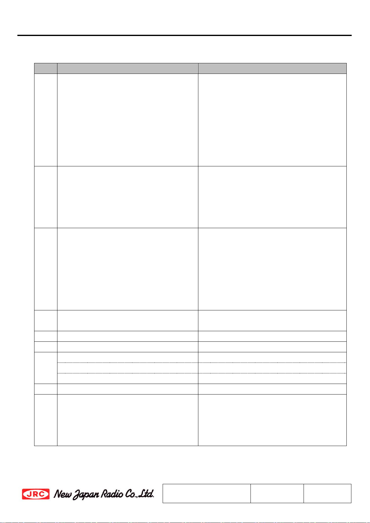
Model No. NJR2935 series
Model No.
RF
Frequency
Local
Frequency
IF
Frequency
NJR2934 series
12.2 to 12.75 GHz
11.25 GHz
950 to 1,500 MHz
NJR2935 series
11.7 to 12.2 GHz
10.75 GHz
950 to 1,450 MHz
NJR2936 series
12.25 to 12.75 GHz
11.3 GHz
950 to 1,450 MHz
NJR2937 series
10.95 to 11.7 GHz
10 GHz
950 to 1,700 MHz
NJR2939 series
11.2 to 11.7 GHz
10.25 GHz
950 to 1,450 MHz
Local Reference Type: Internal Reference
Local Stability: Same as External Reference Stability
RF Input Interface: Waveguide, WR-75 with Groove
IF Output Interface: N-type / F-type, Female Connector
DC Power Input: IF Output Interface Connector
DC Power Voltage Range: +12 to +24 V
Copyright ©
New Japan Radio Co., Ltd.
Microwave Division
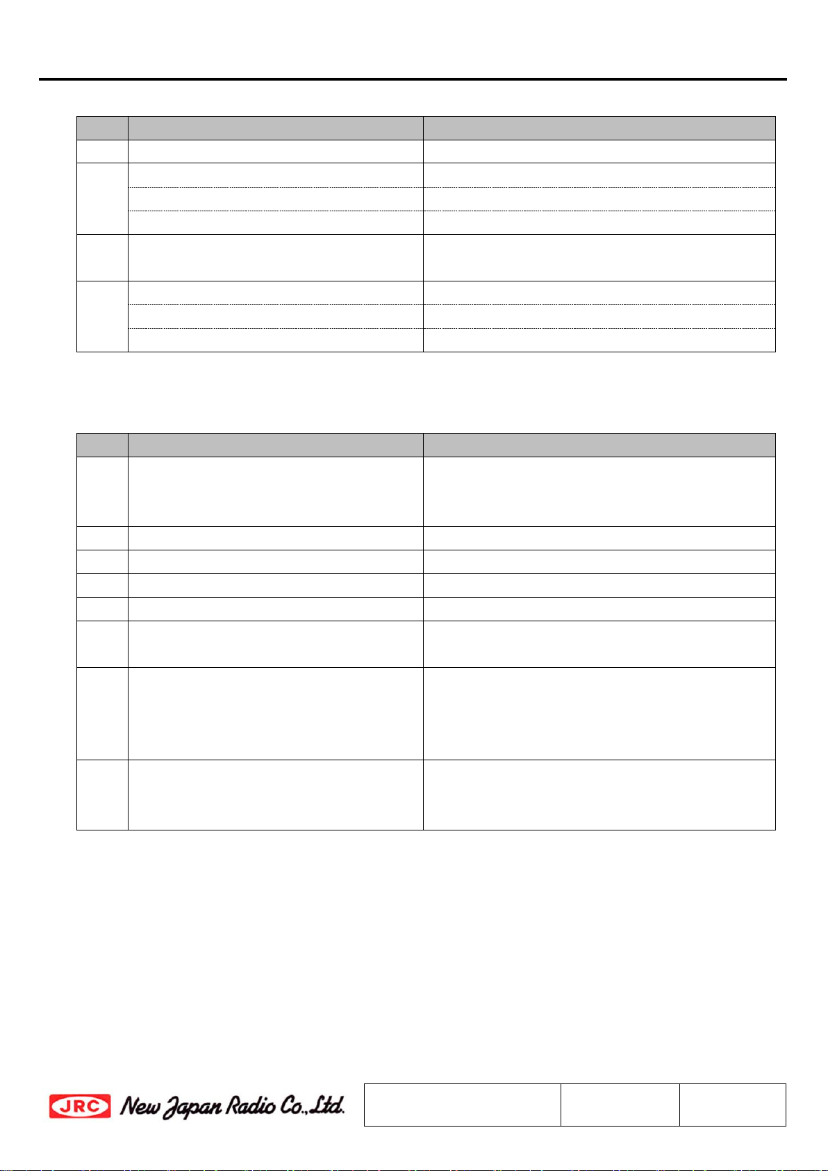
-Notice of Proprietary Information-
This document and contents are proprietary to New Japan Radio Co., Ltd.
This publication and contents may not be reproduced or distributed for any other purpose
without the written permission of New Japan Radio Co., Ltd.
Specifications listed in this document are subject to change at any time, without notice.
New Japan Radio Co., Ltd.
Microwave Division
Title:
Datasheet of NJR2935 series
Reference No.:
DS-R2935
Rev.:
10E
Sheet:
1 / 17
Released
NJR2935 series
*Above specifications are subject to change without notice.
Reference No.:
DS-R2935
Rev.:
10E
Sheet:
2
Caution
1. While New Japan Radio., Ltd.(NJR) continually strives to improve the quality and reliability of any products, failures would occur in
microwave products over time. For this reason, it is important that customers fulfill their responsibilities to ensure designed-in
safety – including failsafe functions, redundancy, and measures to prevent malfunctions and the spread of fire – in order to avoid
injuries, accidents, or social repercussions resulting from the failure of any product related to satellite communications on this
document (hereinafter, “the product”). Customers must pay careful attention to ensuring the safety of their equipment.
2. The product is designed and tested to function in accordance with its specifications. Do not use under conditions that deviate from
the product specifications included in the specifications. NJR assumes no responsibility and shall not be liable for any injuries,
accidents, or social repercussions resulting from the product being in a poor or damaged state because it was used under conditions
that depart from the specifications.
3. The product is covered by a warranty for one year following delivery unless otherwise stipulated in the contract or delivery
conditions. In the event of a failure for which NJR are responsible occurring during the warranty period, NJR undertake to repair or
replace the product free of charge. Note, however, that the warranty does not cover failures such as those listed here (see bullets
below), even if they occur within the warranty period. In addition, in the case of a product being repaired or replaced by us, the
starting date for the warranty period is still the original delivery date of the product.
Failure due to the product being used in conditions other than those stipulated in the data sheet, specification sheet, etc.
Failure due to modifications or repairs carried out by some entity other than our company
Failure determined to be the result of unsuitable maintenance or replacement of a consumable item that requires due
maintenance
Failure due to circumstances that were unforeseeable given the scientific /technological standards at the time of shipment
Other failures due to external factors such as fire, earthquake, flood and power supply anomalies for which NJR are not
responsible
In addition, the product warranty is limited to the provision of repair services or replacement at no cost. It does not cover secondary
damage (to equipment, business opportunities, profits, etc.) or any other damage that may have resulted from failure of the
product.
4. The product must be handled appropriately to ensure its continued reliability. Since it can be damaged by the intrusion of water,
dust, oil, chemicals, etc., it must be given appropriate protection. Even in the case of a product with an airtight construction, avoid
using it in an environment that exceeds the stated levels of waterproofing/dustproofing. Also, be sure to use connectors and
waveguides properly.
If replacement parts such as fans are included, proper maintenance is necessary. To maintain product performance and
functionality, it is necessary to conduct inspections and maintenance at appropriate intervals and exchange replacement parts when
necessary. Improper inspections or maintenance may result in failure.
In addition, the warranty does not cover the use of the product in areas where salt damage can be expected or where there is a
substantial presence of corrosive gases such as Cl2, H2S, SO2, and NO2. If the product is to be used in such areas, at the time of
installation you must take appropriate steps to protect the product.
5. If the product is to be used with equipment/systems that must meet special quality and reliability standards (aerospace equipment,
medical equipment, power generation control equipment, automotive/railway transportation equipment, safety equipment,
disaster prevention and security equipment, etc.), please consult with our sales staff in advance.
6. This product contains gallium arsenide (GaAs), classified as a harmful substance. To avoid danger, do not incinerate, crush, or
chemically treat the product in such a way that gases or dust are released. When disposing of the product, comply with all applicable
laws and regulations and do not treat it as general industrial waste or household waste.
7. When exporting a product or technology, observe export laws and regulations such as those governing foreign exchange and foreign
trade, and obtain any necessary licenses for export, service transactions, etc. NJR request that you do not use our products or the
technical data published on this document for developing weapons of mass destruction or for any other military purposes or
applications.
8. The product specifications in this document are subject to change without notice. If you are considering using a product, delivery
specifications must first be settled.
NJR2935 series
*Above specifications are subject to change without notice.
Reference No.:
DS-R2935
Rev.:
10E
Sheet:
3
Scope
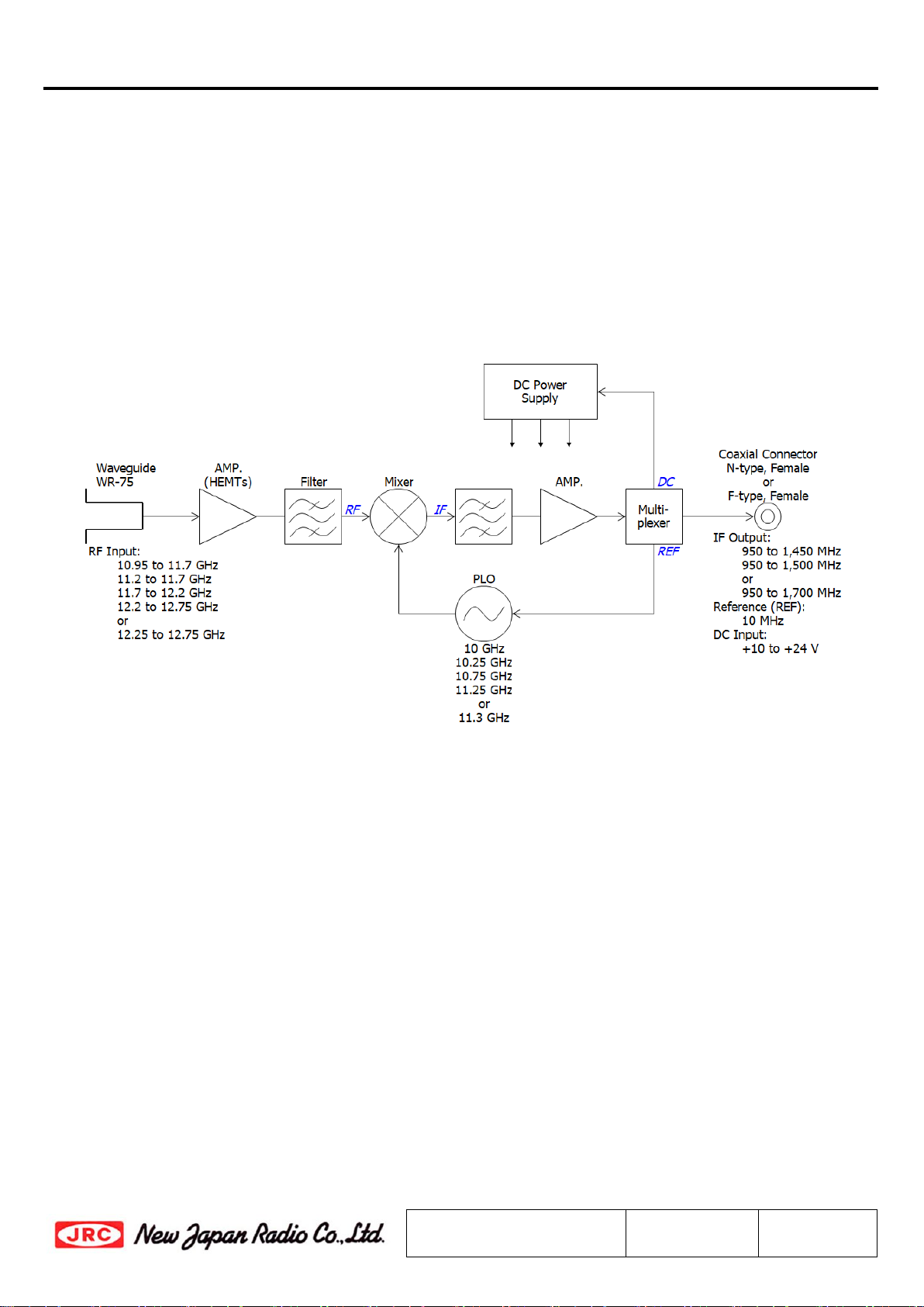
This LNB is designed for the low noise amplifier and block downconverter intended for the satellite
communication data downlink application in Ku-band. It is combined a 3-stage HEMT amplifier and a block
downconverter with a phase locked local oscillator (10 GHz, 10.25 GHz, 10.75 GHz, 11.25 GHz, or 11.3
GHz) which is synchronized with external 10MHz reference.
The LNB receives an RF signal (Ku-band: frequency divided by region band from the 10.75 to 12.75
GHz) as input, downconverts from the RF signal to an IF signal (L-band: 950 to 1,700 MHz), and outputs
the IF signal. It is operated by +24 V DC power (range: +12 to +24 V) input.
The LNB comes in a single, weatherized housing rated for outdoor use, and has a WR-75 waveguide
flange with groove as RF input and an either an N-type or F-type female connector as IF output.
Fig.1 Functional Block Diagram

NJR2935 series
*Above specifications are subject to change without notice.
Reference No.:
DS-R2935
Rev.:
10E
Sheet:
5
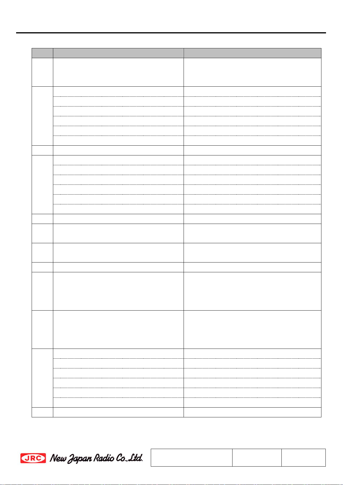
1. Electrical Specifications
#
Items
Specifications
1.1.
Absolute Maximum Rating
[RF Input Power]
[Supply Voltage]
-10 dBm (@ CW)
+28 V DC
1.2.
Input RF Frequency Range
<Model No. NJR2934>
12.2 to 12.75 GHz
<Model No. NJR2935>
11.7 to 12.2 GHz
<Model No. NJR2936>
12.25 to 12.75 GHz
<Model No. NJR2937>
10.95 to 11.7 GHz
<Model No. NJR2939>
11.2 to 11.7 GHz
1.3.
Noise Figure @ +25 ºC
0.8 dB typ., 1.0 dB max.
1.4.
Output IF Frequency Range
<Model No. NJR2934>
950 to 1,500 MHz
<Model No. NJR2935>
950 to 1,450 MHz
<Model No. NJR2936>
950 to 1,450 MHz
<Model No. NJR2937>
950 to 1,700 MHz
<Model No. NJR2939>
950 to 1,450 MHz
1.5.
Conversion Gain @ +25 ºC
55 dB min., 60 dB typ.
1.6.
Conversion Gain Ripple @ +25 ºC 2 dBp-p max.
at any 50 MHz segments.
1.7.
Conversion Gain Flatness over Frequency
@ +25 ºC
5 dBp-p max. over Receive Bandwidth
1.8.
Output Power @ 1dB G.C.P. (P1dB)
0 dBm min.
1.9.
Intermodulation Products
(3rd order Intermodulation rejection with
two two RF input carriers separated by 10
MHz, -10 dBm IF Output Power.)
45 dBm min.
1.10.
Tx Signal Immunity
[Gain Change]
[Noise Figure Change]
0.2 dB max.
0.1 dB max.
at -20 dBm Tx Input (13.75 to 14.5 GHz)
1.11.
Local Oscillator Frequency
<Model No. NJR2934>
11.25 GHz nom.
<Model No. NJR2935>
10.75 GHz nom.
<Model No. NJR2936>
11.3 GHz nom.
<Model No. NJR2937>
10 GHz nom.
<Model No. NJR2939>
10.25 GHz nom.
1.12.
Local Oscillator Frequency Stability
Same as External Reference Stability
NJR2935 series
*Above specifications are subject to change without notice.
Reference No.:
DS-R2935
Rev.:
10E
Sheet:
6
#
Items
Specifications
1.13.
Requirement for External Reference
[Input Port]
[Frequency]
[Input Power]
[Phase Noise]
IF Output Interface Connector
(Combine reference with IF Signal)
10 MHz (sine-wave)
-10 to 0 dBm @IF Output connector
-135 dBc/Hz max. at 100 Hz
-143 dBc/Hz max. at 1 kHz
-145 dBc/Hz max. at 10 kHz
(Input Condition)
1.14.
L.O. Phase Noise (SSB) -70 dBc/Hz typ. at 100 Hz
-80 dBc/Hz typ. at 1 kHz
-82 dBc/Hz typ. at 10 kHz
-97 dBc/Hz typ. at 100 kHz
*Depend on Phase Noise of the External
Reference.
1.15.
Spurious a) -140 dBm max.
at input, Fixed frequency spur, unrelated to
test CW signal. (Measured at specified IF
band: 950 to 1,450 MHz or 1,700 MHz)
b) -50 dBc max.
with test CW signal -
10 dBm IF output
(Measured at specified IF band: 950 to
1,450 MHz, or 950 to1,700 MHz)
1.16.
Local Oscillator Leakage Levels -25 dBm max. at the IF Output Connector.
-60 dBm max. at the RF Input Flange.
1.17.
Image Rejection
45 dB min.
1.18.
Input V.S.W.R.
2.5 : 1 typ.
1.19.
Output Impedance
<N-type Model>
50 ohms nom
<F-type Model>
75 ohms nom.
1.20.
Output V.S.W.R.
2.3 : 1 max.
1.21.
Power Requirement
[Input Port]
[Input Voltage]
[Current Drain]
IF Output Interface Connector
(Combine DC Power with Output IF Signal)
+12 to +24 VDC
250 mA max.
NJR2935 series
*Above specifications are subject to change without notice.
Reference No.:
DS-R2935
Rev.:
10E
Sheet:
7
2. Mechanical Specifications
#
Items
Specifications
2.1.
Input Waveguide Flange
Waveguide, WR-75 (with Groove)
2.2.
IF Interface Connector
<F-type Model>
Coaxial Connector , F-type Female - 75 ohms
<N-type Model>
Coaxial Connector , N-type Female - 50 ohms
2.3.
Dimension & Housing
without Interface Connector
100.5 (L) x 40 (W) x 40 (H) mm
[3.96” (L) x 1.57” (W) x 1.57” (H) ]
2.4.
Weight
<F-type Model>
230 g [0.51 lbs]
<N-type Model>
260 g [0.57 lbs]
3. Environmental Specifications
#
Items
Specifications
3.1.
Temperature Range (Ambient)
[Operating]
[Storage]
-40 to +60 ºC
-40 to +80 ºC
3.2.
Humidity
0 to 100 % RH
3.3.
Altitude
15,000 feet (4,572 m)
3.4.
Vibration (Survival)
5 G [49.03 m/s
2
] (3 axis, 50 Hz)
3.5.
Shock (Survival)
15 G [147.1 m/s
2
] (3 axis)
3.6.
Waterproof / Dustproof
(IP Code Rating)
IP 67
3.7.
Regulations EU Directive (CE Marking)
EMC - 2014/30/EU
RoHS - 2011/65/EU + (EU)2015/863
Safety: EN60950-1
3.8.
MTBF
(by Method of Parts Count Reliability
Prediction)
150,000 hours and more at +60 ºC
as Design Condition


NJR2935 series
*Above specifications are subject to change without notice.
Reference No.:
DS-R2935
Rev.:
10E
Sheet:
13
7. Handling Precautions
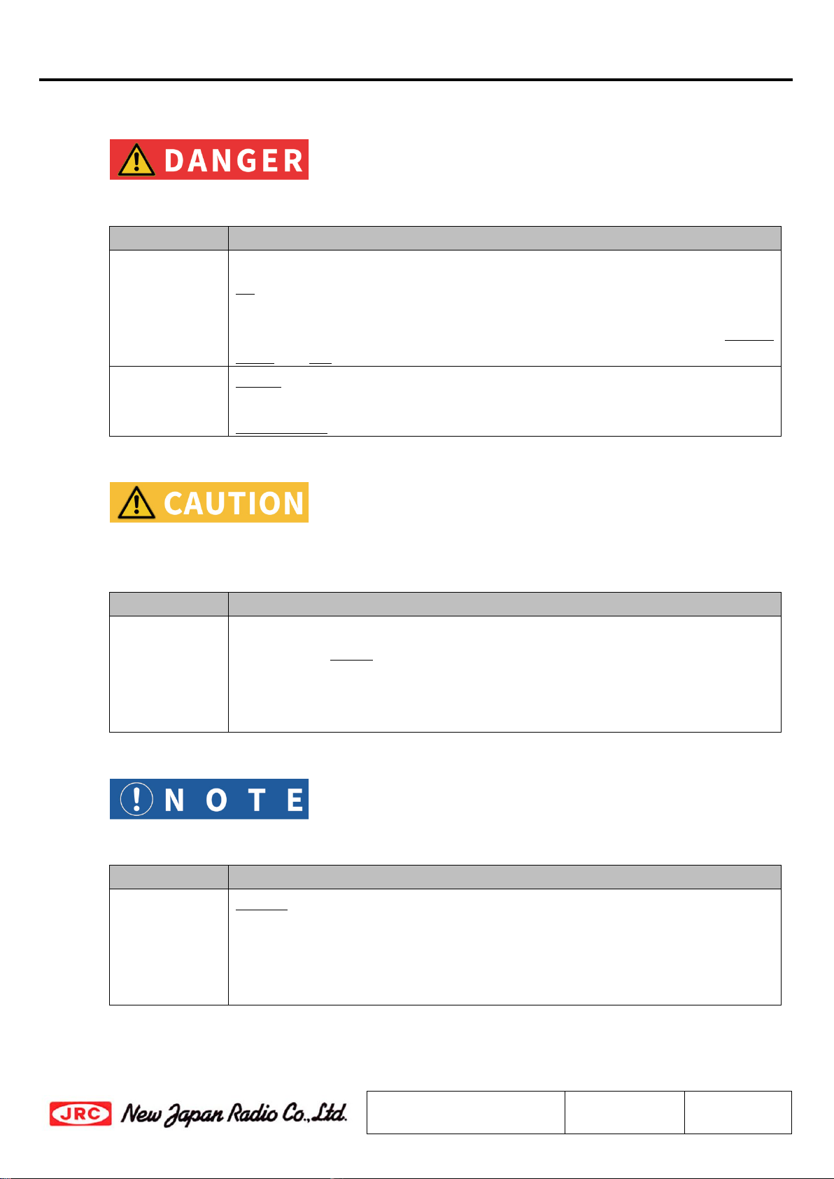
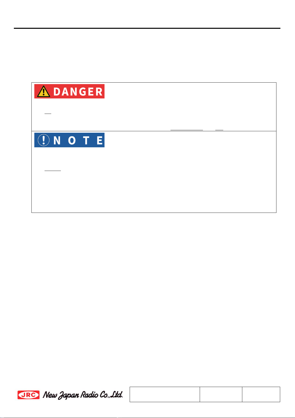
7.1. DANGER
This statement indicates an imminently hazardous situation which, if not avoided, will result in
death or serious injury.
Items
Description
Input Voltage Only input a DC voltage within the range indicated in specifications.
Do operate with the input voltage range between +12 and +24 V DC power.
When applying higher voltage than specifications (+28 V as absolute maximum
rating), it will not only cause this unit failure, but it may also result in electric
shock and fire.
Disassembling Do not disassemble the unit.
Disassembling will not only cause this unit
failure, but it may also result in
electric shock.
7.2. CAUTION
This statement indicates a potentially hazardous situation which, if not avoided, could result in
minor or moderate injury. The statement may also be used to indicate other unsafe practices or
risks of property damage.
Items
Description
Disposal This unit contains gallium arsenide (GaAs), classified as a harmful substance. To
avoid danger, do not incinerate, crush, or chemically treat the unit in such a way
that gases or dust are released.
When disposing the unit, comply with all applicable laws and regulations and do
not treat it as general industrial waste or household waste.
7.3. NOTE
This statement is used to notify of installation, operation, or maintenance information that is
important, but not hazard-related.
Items
Description
Torque
Management
Do not tighten with excessive torque when attaching screws/bolts and
connectors.
The following value as tighten torque is recommended.
Screws/Bolts - M4: 1.15 to 1.4 N⋅m
IF Connector (N-type / F-type): 0.68 to 1.13 N⋅m
NJR2935 series
*Above specifications are subject to change without notice.
Reference No.:
DS-R2935
Rev.:
10E
Sheet:
14
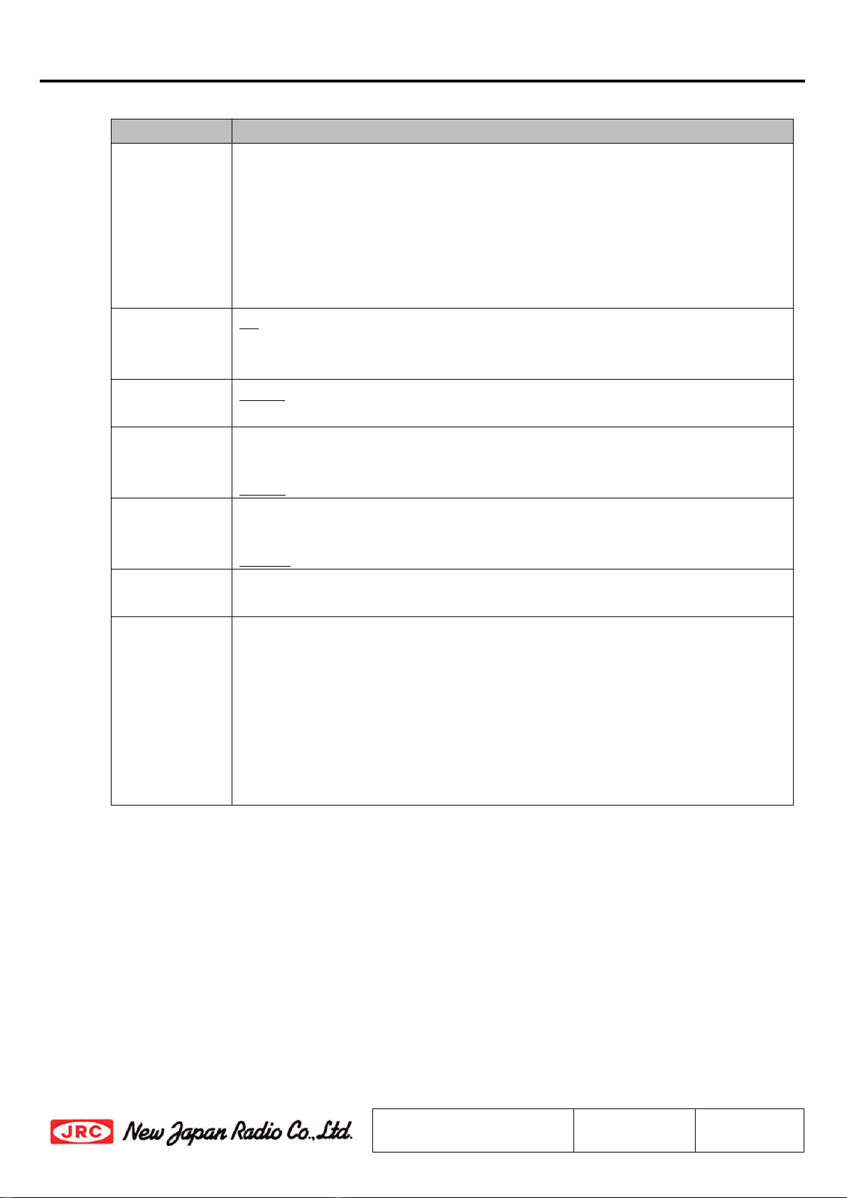
Items
Description
Weatherproof
The unit mounted in outdoor should be conducted with adequately
weatherproof procedure.
Do seal all of cable connection points from the connector to the cable sheath by
usage of self-amalgamating tape.
Ensure the waveguide connection is properly assembled
with the supplied
o-ring gasket as accessories.The o-ring gasket is full-type and it is assumed to
connect the unit to a flat waveguide flange (no grooved waveguide flange).
Input Voltage Do operate with the input voltage range between +12 and +24 V DC power.
Avoid applying more than the maximum voltage in this range (including ripple
voltage) under any conditions.
Input RF Signal
Power
Do not supply the input RF signal over the absolute maximum rating indicated in
specifications (-10 dBm @ CW / +10 dBm @ Pulse).
Input 10MHz
Signal Power
The 10 MHz reference signal should be supplied with the range between -10 and
0 dBm with sine-wave for correctly operation.
Do not supply the signal level of more than +13 dBm.
High
Temperature
Operation
It may cause damage and/or degradation of reliability / lifetime to operate the
unit in a condition where the ambient temperature exceeds the maximum value,
+60 °C, at operating temperature described in the specifications.
Vibration
/Shock
When vibration and/or shock impact exceeding the conditions described in the
specifications is applied, internal parts may be damaged.
Warranty The unit is covered by a warranty for one(1)
year following delivery unless
otherwise stipulated in the contract or delivery conditions.
Repairs may be possible under payment of charge even for the unit whose
warranty period has expired.
Opening, removing, disassembling and modifying any parts and components
(including the product label, sealing tape and screws) without fan equipment
will immediately void the warranty.
In any case, the unit of invalid warranty cannot be repaired.
NJR2935 series
*Above specifications are subject to change without notice.
Reference No.:
DS-R2935
Rev.:
10E
Sheet:
15
8. Instructions Manual
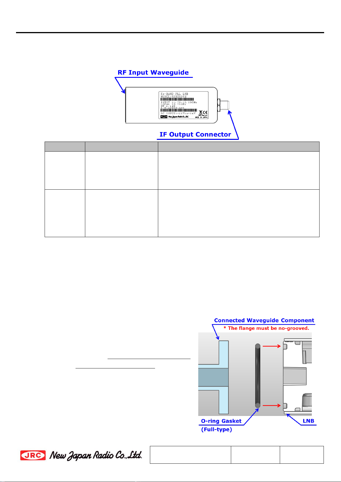
8.1. Descriptions
This section describes the information of connectors and etc.
Items
Description
Purpose
RF Input
Waveguide
Waveguide: WR-75
Flange: Square Cover
Grooved
(Equivalent to PBR 120)
The LNB receives an RF signal of Ku-band (Low-band:
10.7 to 11.7 GHz / High-band: 11.7 to 12.75 GHz) via
this waveguide.
IF Output
Connector
F-type Female Coaxial
Connector, 75 Ohms
OR
N-type Female Coaxial
Connector, 50 Ohms
The LNB outputs an IF signal of L-band (950 to 1,700
MHz) and requires to supply +12 to +24
V DC power
and a 10 MHz reference signal via this connector.
8.2. Connection and Installation
This section describes basic installation for the LNB.
8.2.1. Mounting Configuration
The Unit can be mounted with OMT or the waveguide filter of the satellite antenna.
When mounting with the OMT or the waveguide filter, the following steps should be complied:
Step 1: Verify that the groove on the waveguide
flange for a gasket is clean.
The enclosed o-ring gasket as accessories
is full-type and it is assumed to connect
the LNB to a flat waveguide flange (non-
grooved waveguide flange). Insert the
o-ring gasket the groove as shown in the
figure on the right. The o-ring gasket and
flange groove dimensions is customized
and optimized for this LNB; therefore any
other o-ring gasket than the enclosed
accessory is not permitted for using.
NJR2935 series
*Above specifications are subject to change without notice.
Reference No.:
DS-R2935
Rev.:
10E
Sheet:
16
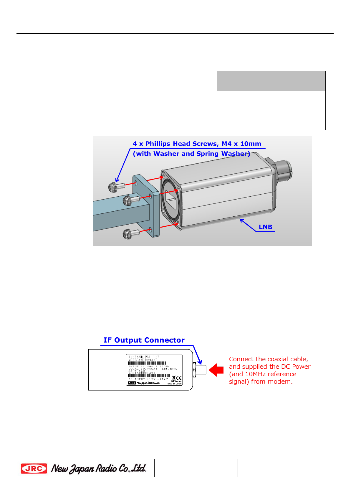
Flange Thickness
of OMT/Filter
Screw
Length
3 to 5 mm
10 mm
5 to 7 mm
12 mm
7 to 9 mm
14 mm
9 to 11 mm
16 mm
Step 2: Secure the OMT or the filter to the LNB by tightening the enclosed Phillips head screws
(M4 x 10 mm) with 1.15 to 1.4 N⋅m torque as shown in the figure below, when the
thickness of the flange of the OMT or filter is
assumed to be 3 to 5 mm. The enclosed
washers as accessory must be inserted to
bolts before tightening bolts.
When the thickness is exceed 5 mm, the
appropriate length screws or bolts based
should be prepared on the table on the right.
8.2.2. Connecting Coaxial Cable
The LNB is connected the modem with a coaxial cable, and requires to supply +12 to +24 V DC power
and a 10 MHz reference from the modem.
The connection of coaxial cable should be complied with the following steps:
Step 1: Connect the coaxial cable with the N or F-type male connectors to the coaxial connecter
equipped with the LNB which is shown in the figure on the right below under 0.68 to
1.13 N⋅m tighten torque.
Step 2: Use self-amalgamating tape to seal connector and cable entry points from the
connector to the cable sheath.
Do not power on the modem before finishing all of steps of Connecting Coaxial Cable.
NJR2935 series
*Above specifications are subject to change without notice.
Reference No.:
DS-R2935
Rev.:
10E
Sheet:
17
8.2.3. Start-up
Start-up will be immediately performed with the following step:
Step: Power on the modem and supply the DC voltage and 10 MHz reference from modem.
Only input a DC voltage within the range indicated in specifications.
Do operate with the input voltage range between +12 and +24 V DC power.
When applying higher voltage than specifications (+28 V as absolute maximum rating), it will not
only cause this unit failure, but it may also result in electric shock and fire.
The 10 MHz reference signal should be supplied with the range between -10 and 0 dBm with
sine-wave for correctly operation.
Do not supply the signal level of more than +13 dBm.
Do not power on the modem before finishing all of steps of Connecting Coaxial Cable.
The LNB must be adequately weatherproofed to place in outdoor.
Ensure that the waveguide joint is properly sealed with the enclosed o-ring gasket.
Do seal all of cable connection points from the connector to the cable sheath by usage of
self-amalgamating tape.
This manual suits for next models
13
Table of contents
Other New Japan Radio Power Supply manuals


Popular Power Supply manuals by other brands

Videx
Videx 520MR Installation instruction

Poppstar
Poppstar 1008821 Instructions for use

TDK-Lambda
TDK-Lambda LZS-A1000-3 Installation, operation and maintenance manual

TDK-Lambda
TDK-Lambda 500A instruction manual

Calira
Calira EVS 17/07-DS/IU operating instructions

Monacor
Monacor PS-12CCD instruction manual


