PI 2 Design Pi 2 Media PI2AES Quick user guide

PI2Media PI2AES Hardware Reference Manual –P3.4 - 06/02/2020
PAGE 1
PiPiPi 222 MediaMediaMedia
PI2AES
Digital Pro Audio Hat
Hardware Reference Manual
© 2019 PI 2 Design

PI2Media PI2AES Hardware Reference Manual –P3.4 - 06/02/2020
PAGE 2
Table of Contents
1 Warranty ................................................................................................................................................................................................4
2 Operating Specifications .......................................................................................................................................................................5
2.1 PI2AES Operating specifications...................................................................................................................................................5
3 Overview................................................................................................................................................................................................6
3.1 Introduction ....................................................................................................................................................................................6
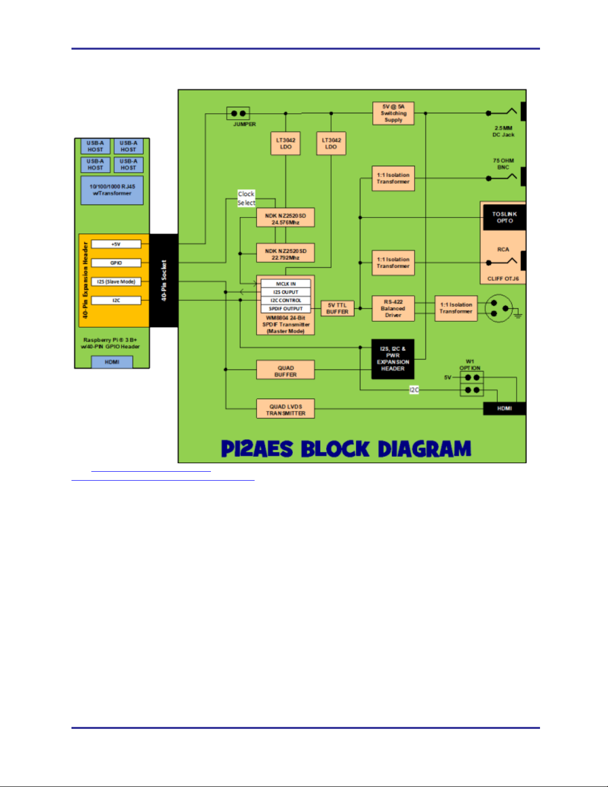
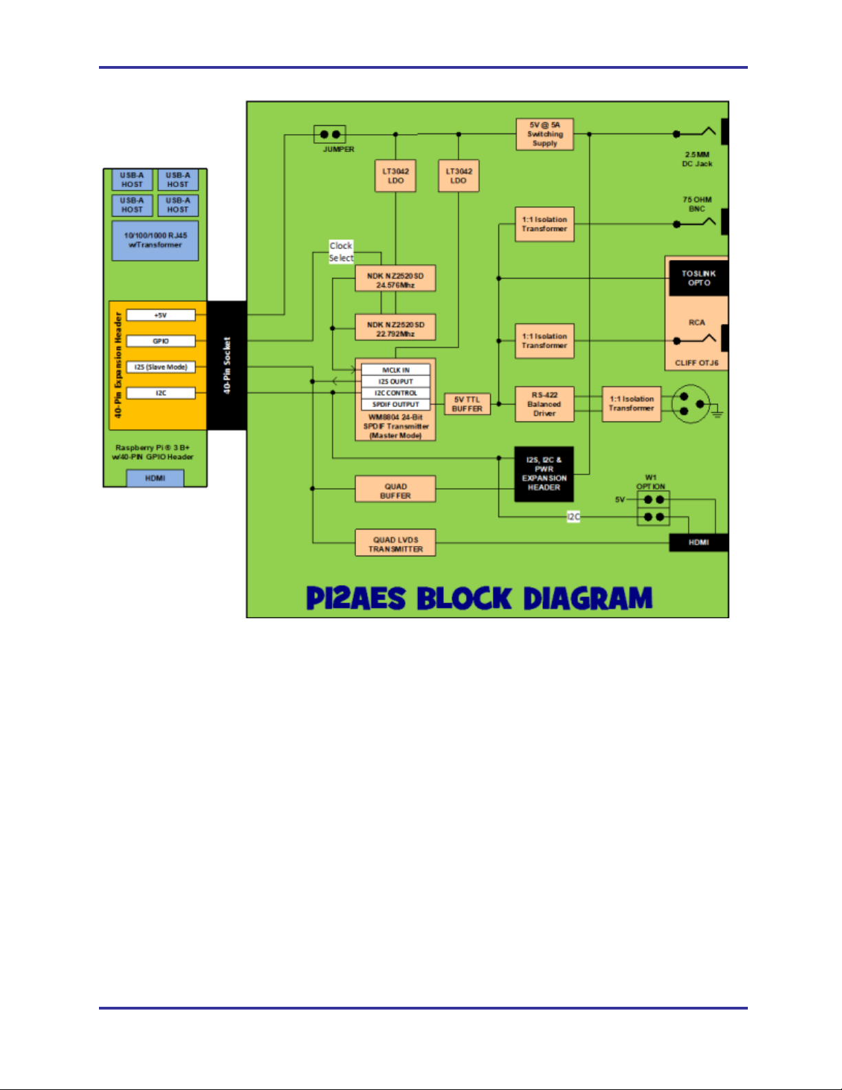
3.2 Block Diagram................................................................................................................................................................................6
4 On-Board Devices .................................................................................................................................................................................8
4.1 Overview ........................................................................................................................................................................................8
4.1 PI2AES I2C Bus Devices...............................................................................................................................................................8
4.1 WM8804 SPDIF Transmitter..........................................................................................................................................................8
4.1.1 WM8804 SPDIF Transmitter Notes .......................................................................................................................................9
4.2 Dual High Resolution NDK Clocks ................................................................................................................................................9
4.3 RS-422 Differential Transmitter .....................................................................................................................................................9
4.4 I2S Parallel Buffer..........................................................................................................................................................................9
4.5 I2S Differential Driver.....................................................................................................................................................................9
4.6 Audio Data Rate and Power LED’s ...............................................................................................................................................9
5 RPi GPIO.............................................................................................................................................................................................10
5.1 Overview ......................................................................................................................................................................................10
5.1.1 RPi GPIO Notes ...................................................................................................................................................................11
6 PI2AES Power.....................................................................................................................................................................................12
6.1 Overview ......................................................................................................................................................................................12
7 PI2AES Software.................................................................................................................................................................................13
7.1 Overview ......................................................................................................................................................................................13
8 PI2AES Connectors ............................................................................................................................................................................14
8.1 Overview ......................................................................................................................................................................................14
8.2 J1 –DC Jack................................................................................................................................................................................16
8.3 J2 –BNC......................................................................................................................................................................................16
8.4 P1 –40-Pin GPIO Header (Bottom Side) ....................................................................................................................................16
8.5 P2 - I2S Expansion Header .........................................................................................................................................................16
8.1 P3 –XLR Balanced Output..........................................................................................................................................................17
8.2 P4 –I2S Over HDMI ....................................................................................................................................................................17
8.3 W1 –I2S Over HDMI Options......................................................................................................................................................17
8.4 U9 –Combo RCA/Opto Transmitter............................................................................................................................................18
9 Document Revisions ...........................................................................................................................................................................19
10 Errata.................................................................................................................................................................................................20
10.1 Overview ....................................................................................................................................................................................20
List of Tables
Table 1 –PI2AES Operating Specifications ............................................................................................................................................5
Table 2 –PI2AES I2C Bus Devices .........................................................................................................................................................8
Table 3 –RPi to WM8804 Connections ...................................................................................................................................................9
Table 4 –CPU GPIO Pin Assignments..................................................................................................................................................11
Table 5 –I2S Expansion Header Pinout................................................................................................................................................16
Table 6 –I2S Over HDMI Pinout............................................................................................................................................................17
Table 7 –Document Revisions ..............................................................................................................................................................19

PI2Media PI2AES Hardware Reference Manual –P3.4 - 06/02/2020
PAGE 3
List of Figures
Figure 1 –PI2AES Block Diagram..................................................................................................................................................7
Figure 2 –PI2AES Power, Simplified Block Diagram ............................................................................................................................12

PI2Media PI2AES Hardware Reference Manual –P3.4 - 06/02/2020
PAGE 4
111 WARRANTYWARRANTYWARRANTY
The enclosed product ("the Product"), a part of the PI2MEDIA Shield/Hat series, is
warranted by Pi 2 Design for a period of one year for reasonable development, testing
and use, all as further described and defined below. This warranty runs solely to the
individual or entity purchasing the Product and is not transferable or assignable in any
respect. This warranty is valid only for so long as the product is used intact as shipped
from PI 2 Design. Any attempt or effort to alter the Product, including but not limited to
any attempt to solder, de-solder, unplug, replace, add or affix any part or component of
or onto the Product, other than components specifically intended for the user to plug
and unplug into appropriate sockets and/or Connectors to facilitate user programming,
development and deployment, all as specifically described and authorized in this
Product Hardware Reference Manual, shall void this warranty in all respects. Coverage
under this warranty requires that the Product be used and stored at all times in
conditions with proper electrostatic protection necessary and appropriate for a complex
electronic device. These conditions include proper temperature, humidity, radiation,
atmosphere and voltage (standard commercial environment, 0C to +70C, <60%RH).
Any Product that has been modified without the express, prior written consent of Pi 2
Design is not covered by this warranty. The use or connection of any test or bus
Connector, adapter or component with any device other than a Pi 2 Design Connector
or adapter shall void this warranty and the warranty of all other components, parts and
modules connected to the rest of the system. Pi 2 Design shall not be responsible for
any damage to the Product as a result of a customer's use or application of circuitry not
developed or approved by Pi 2 Design for use on or in connection with the Product.
This warranty does not cover defects caused by electrical or temperature fluctuations or
from stress resulting from or caused by abuse, misuse or misapplication of the Product.
Any evidence of tampering with the serial number on the Product shall immediately void
this warranty. This Product is not intended to be used on or embedded in or otherwise
used in connection with any life-sustaining or life-saving product and this warranty is not
applicable nor is Pi 2 Design liable in any respect if the Product is so used.
Notwithstanding anything to the contrary herein, Pi 2 Design expressly disclaims any
implied warranty of merchantability or implied warranty of fitness for a particular purpose
in connection with the manufacture or use of the Product.

PI2Media PI2AES Hardware Reference Manual –P3.4 - 06/02/2020
PAGE 5
222 OPERATING SPECIFICATIONSOPERATING SPECIFICATIONSOPERATING SPECIFICATIONS
2.1 PI2AES OPERATING SPECIFICATIONS
The PI2AES conforms to the following specifications:
Specification
Value
Dimensions
85mm x 56.5mm
Weight
~10g
Storage Temperature
-20C to +85C
Operating Temperature
0C to +70C
Humidity
0% to 95% RH, Non-Condensing
Input Voltage (VIN)
+24V to +48V
Power Consumption
250mw Typical, 1W Maximum
Table 1 –PI2AES Operating Specifications

PI2Media PI2AES Hardware Reference Manual –P3.4 - 06/02/2020
PAGE 6
333 OVERVIEWOVERVIEWOVERVIEW
3.1 INTRODUCTION
The PI2AES, designed and manufactured by PI 2 Design, is a professional I/O Shield
designed to bring Professional Studio Grade Audio to the Raspberry PI ®family of
Single Board Computers. This low-cost Shield converts the Raspberry Pi ®I2S
Interface to High Definition Digital Audio Coax, OPTO and Balanced XLR.
The addition of Parallel I2S Output along with LVDS Differential over HDMI allows the
PI2AES to interface with virtually any High Performance DAC on the market.
The major features of the PI2AES are as follows:
FORM FACTOR –Raspberry Pi ®Shield Size w/40-Pin mating connector.
AES TRANSMITTER –The industry standard WM8804 converts the RPi I2S stream to AES3/SPDIF
formatted data at 24-Bit up to 192Khz Frame Rate
SPDIF COAX OUTPUT –An RCA connector with Isolation Transformer provides coaxial transmission
of the SPDIF Audio Data Stream.
SPDIF OPTICAL OUTPUT –Isolated Optical Transmitter Supports Consumer Level DAC and AVR
inputs
AES BNC OUTPUT - A 75 ohm BNC connector with Isolation Transformer provides for Single Ended
AES transmission.
AES BALANCED OUTPUT –An RS-422 Transmitter coupled with Isolation Transformer allows the
transmission of balanced audio data with 110 ohm impedance via the Professional Audio Standard
XLR Connector
BUFFERED I2S OUTPUT –Parallel Buffered I2S is available for direct short distance connection to
off-board D/A. Perfect for DIY use! I2C for control is also provided as well as 5V Regulated and Input
Voltage Rails.
DIFFERENTIAL I2S OUTPUT –A DS2063 Differential Transmitters is used to drive the I2S Bus over
a standard HDMI Connector.
HIGH RESOLUTION CLOCKS –A pair of Ultra-Low Noise NDK NZ2520SD oscillators allow the
WM8804 to operate in non-PLL mode for the lowest possible noise.
ULTRA-LOW NOISE LDO’s –Ultra-Low Noise AP1155ADL LDO (30uV noise and 80dB PSRR) is
used to Supply the WM8804 Transmit Section, while an ADP150 (9uV noise and 70dB PSRR) and
the High-Resolution Clocks.
LOW NOISE PCB LAYOUT –Constructed with 4-layer Split Ground PCB with noise reduction
techniques refined from years of High-Speed Mixed-Signal Design work
3.2 BLOCK DIAGRAM
Refer to the following figure for a block diagram of the PI2AES Shield.

PI2Media PI2AES Hardware Reference Manual –P3.4 - 06/02/2020
PAGE 7
Figure 1 –PI2AES Block Diagram

PI2Media PI2AES Hardware Reference Manual –P3.4 - 06/02/2020
PAGE 8
444 ON-BOARD DEVICESON-BOARD DEVICESON-BOARD DEVICES
4.1 OVERVIEW
The PI2AES interfaces to the RPi via the 40-Pin GPIO Connector. This section
describes in detail the devices located on the PI2AES.
4.1 PI2AES I2C BUS DEVICES
The following table describes the CPU I2C Bus usage of the PI2AES. Most of these
addresses are set by the startup script supplied by Pi2Design. Refer to the respective
device documentation for more detail.
I2C
Bus
7-Bit I2C
Address
Description
I2C
0x3B
WM8804 SPDIF Transmitter
Table 2 –PI2AES I2C Bus Devices
4.1 WM8804 SPDIF TRANSMITTER
At the core of the PI2AES is the Cirrus Logic WM8804 AES Digital Audio Transmitter.
This device interfaces to the Raspberry Pi via I2S and I2C. The signals used to interface
with the WM8804 are shown in the following table.
WM8804
Signal
RPi
Signal
Description
MCLK
-
Unused
BCLK
BCLK
I2S Bit Clock Output to Pi
LRCLK
LRCLK
I2S Word Clock Output to Pi
SDIN
SDOUT
I2S Serial Audio Data Input from Pi
SCL
SCL
I2C Clock from Pi
SDA
SDA
I2C Data to/from Pi
XIN
GPIO5
1 = Select 22.5792Mhz Input Clock for 44.1Khz,
88.2Khz and 176.4Khz Frame Rates
XIN
GPIO6
1 = Select 24.576Mhz Input Clock for 48Khz,
96Khz and 192Khz Frame Rates
TXO
-
AES3/SPDIF encoded digital audio output

PI2Media PI2AES Hardware Reference Manual –P3.4 - 06/02/2020
PAGE 9
Table 3 –RPi to WM8804 Connections
4.1.1 WM8804 SPDIF TRANSMITTER NOTES
1. The WM8804 is controlled using the I2C port. Refer to the WM8804
documentation and Pi 2 Design supplied driver code for more detail.
2. The PI2AES is designed to operate the WM8804 in Master mode. In this
mode the WM8804 receives its master clock from XIN and drives MCLK
(unused), BCLK and LRCLK to the Pi. Serial Data in is received from Pi.
3. Pi GPIO’s 6 and 13 are used to select the desired clock input. GPIO 6 and
13 are pulled low by default. CAUTION - Do not select more than one
clock at a time!
4.2 DUAL HIGH RESOLUTION NDK CLOCKS
A pair of NDK NZ2520SD Ultra-Low Noise clocks provide the critical timing signals for
the WM8804. They are selected via Raspberry PI GPIO5 (22.5792Mhz) and GPIO6
(24.576Mhz).
4.3 RS-422 DIFFERENTIAL TRANSMITTER
An RS-422 Differential Transmitter accepts the SPDIF output from the WM8804 and
sends it as a balanced pair to the 1:1 Isolation Transformer and then to the XLR
connector.
4.4 I2S PARALLEL BUFFER
A 74FCT125 CMOS Buffer is used to drive the I2S signals (MCLK, BCKL, LRCLK and
SDO) to the I2S Expansion Header. This device is designed to drive the I2S Bus short
distances (<12 inches).
4.5 I2S DIFFERENTIAL DRIVER
A DS2063 Quad Differential LVDS Driver takes the I2S Bus and converts each signal
into a balanced differential signal. This is then connected to the HDMI connector. This
device is designed to drive the I2S Bus up to 3 meters.
4.6 AUDIO DATA RATE AND POWER LED’S
A triple stack LED is used to provide visual indication of: Power On (Green), Audio Data
Rate of 48/96/192Khz (Yellow) and Audio Data Rate of 44.1/88.2/176.4Khz (Red).

PI2Media PI2AES Hardware Reference Manual –P3.4 - 06/02/2020
PAGE 10
555 RPIRPIRPI GPIOGPIOGPIO
5.1 OVERVIEW
The PI2AES uses a number of signals from the RPi GPIO header for control and status
purposes. This usage is defined in the following table.
RPi
PIN
DIR
AF
PUP/
PDN
PI2AES
Name
Description/Notes
1
-
-
-
-
RPi +3.3V - Unused
2
-
-
-
+5V
+5V Power to/from the RPi
3
I/O
Y
PUP
I2C_SDA
I2C Bus Data
4
-
-
-
+5V
+5V Power to/from the RPi
5
OUT
Y
PUP
I2C_SCL
I2C Bus Clock
6
-
-
-
GND
7
OUT
-
-
GPIO4
Unused
8
-
-
-
GPIO14
Unused
9
-
-
-
GND
Unused
10
-
-
-
GPIO15
Unused
11
-
-
-
GPIO17
Unused
12
IN
Y
-
BCLK
I2S Bit Clock from WM8804
13
-
-
-
GPIO27
Unused
14
-
-
-
GND
15
-
-
-
GPIO22
Unused
16
-
-
-
GPIO23
Unused
17
-
-
-
-
RPi +3.3V - Unused
18
-
-
-
GPIO24
Unused
19
-
-
-
GPIO10
Unused
20
-
-
-
GND
21
-
-
-
GPIO9
Unused
22
-
-
-
GPIO25
Unused

PI2Media PI2AES Hardware Reference Manual –P3.4 - 06/02/2020
PAGE 11
RPi
PIN
DIR
AF
PUP/
PDN
PI2AES
Name
Description/Notes
23
-
-
-
GPIO11
Unused
24
-
-
-
GPIO8
Unused
25
-
-
-
GND
26
-
-
-
GPIO1
Unused
27
I/O
Y
-
ID_SDA
Unused
28
OUT
Y
-
ID_SCL
Unused
29
-
-
-
GPIO5
1 = Select 22.5792Mhz Clock Input to WM8804
30
-
-
-
GND
31
OUT
-
PUP
GPIO6
1 = Select 24.576Mhz Clock Input to WM8804
32
-
-
-
GPIO12
Unused
33
OUT
-
-
GPIO13
Unused
34
-
-
-
GND
35
IN
Y
-
LRCLK
I2S Left/Right Clock from WM8804
36
-
-
-
GPIO16
Unused
37
-
-
-
GPIO26
Unused
38
-
-
-
GPIO20
Unused
39
-
-
-
GND
40
OUT
Y
-
SDOUT
Pi I2S Serial Audio Data Out
Table 4 –CPU GPIO Pin Assignments
5.1.1 RPI GPIO NOTES
1. DIR is from the point of view of the RPi.
2. Y in the Alternate Function (AF) column indicates that the use of this pin
requires the pin to be assigned to the function as defined by the RPi
specifications.
3. PUP/PDN indicates if the GPIO should have its associated Pullup (PUP)
or Pulldown (PDN) resistor enabled.
4. An asterisk ‘*’at the beginning of the name indicates a low true signal.

PI2Media PI2AES Hardware Reference Manual –P3.4 - 06/02/2020
PAGE 12
666 PI2AES POWERPI2AES POWERPI2AES POWER
6.1 OVERVIEW
The PI2AES is designed to be powered from an external +24V to +48V source. Jumper
W2, when installed, allows the Raspberry PI to be powered from the PI2AES. When
jumper W2 is removed, separate 5V power must be supplied to the Raspberry PI.
Note that an on-board protection circuit ensures proper operation when jumper W2 is
installed while power is applied via J1 AND from the Pi (P1) simultaneously.
See the below block diagram for a simplified view of the PI2AES power.
Figure 2 –PI2AES Power, Simplified Block Diagram

PI2Media PI2AES Hardware Reference Manual –P3.4 - 06/02/2020
PAGE 13
777 PI2AES SOFTWAREPI2AES SOFTWAREPI2AES SOFTWARE
7.1 OVERVIEW
Due to the various resources interfaced on the PI2AES, both internal and external to the
RPi, it is necessary to initialize a large number of CPU registers and external devices
before correct operation can begin. These values and their proper sequencing are
beyond the scope of this document. See our web site at http://www.pi2design.com or
Note that for standard Audio Player software, the PI2AES can use the HifiBerry Digi+
Pro driver.

PI2Media PI2AES Hardware Reference Manual –P3.4 - 06/02/2020
PAGE 14
888 PI2AES CONNECTORSPI2AES CONNECTORSPI2AES CONNECTORS
8.1 OVERVIEW
This section provides the type, location and pinout for the various connectors on the
PI2AES. Top View is shown in the following 3D render.

PI2Media PI2AES Hardware Reference Manual –P3.4 - 06/02/2020
PAGE 15
J3
P3
BALANCED AES XLR
U9
RCA COAX
AND OPTO
J1
2.5MM
DC JACK
P4 –I2S
OVER
HDMI
P3 –I2S EXPANSION HEADER
W1
W2
HEA
DER
J2 BNC
PIN 1
PIN 16

PI2Media PI2AES Hardware Reference Manual –P3.4 - 06/02/2020
PAGE 16
8.2 J1 –DC JACK
This jack is designed to accept a 5.5mm x 2.5mm center positive plug for external
power in. Voltage must be +24V to +48V.
8.3 J2 –BNC
This 75 Ohm Jack is used to transmit Single Ended AES digital audio output.
8.4 P1 –40-PIN GPIO HEADER (BOTTOM SIDE)
This is a standard 40-Pin .1”Dual Row Female Header. It is designed to accept a
Raspberry Pi single board and conforms to the standard Raspberry Pi 40-Pin GPIO
Header pinout.
8.5 P2 - I2S EXPANSION HEADER
This is a 16-Pin, .1”Single Row Header that carries I2S, I2C, and Power for expansion
use. The Pinout for P2 is shown in the following table.
P2 PIN
Name
Description
1
5V
+5V direct from Regulator
2
5V
+5V direct from Regulator
3
GND
Ground
4
MUTE
1 = Mute On
5
SCL
I2C Clock
6
SDA
I2C Data
7
GND
Ground
8
SDO
Buffered I2S Data
9
LRCLK
Buffered I2S Left/Right (Word) Clock
10
BCLK
Buffered I2S Bit Clock
11
GND
Ground
12
MCLK
Buffered I2S Master Clock
13
GND
Ground
14
*PSW
Power Enable –Jumper with Pin 13 for auto on
15
NC
No Pin
16
VIN
+24V to +48V Input from DC Jack
Table 5 –I2S Expansion Header Pinout

PI2Media PI2AES Hardware Reference Manual –P3.4 - 06/02/2020
PAGE 17
8.1 P3 –XLR BALANCED OUTPUT
P3 is a 3-Pin XLR Connector. This 110-ohm connector carries the AES balanced digital
audio output.
8.2 P4 –I2S OVER HDMI
P4 is a standard HDMI Connector that carries the Differential I2S signal. The Pinout for
P4 is shown in the following table.
P4 PIN
Name
Description
1
SDO+
I2S Data Plus
2
GND
Ground
3
SDO-
I2S Data Minus
4
BCK+
I2S Bit Clock Plus
5
GND
Ground
6
BCK-
I2S Bit Clock Minus
7
LRCLK+
I2S Left/Right Clock Plus
8
GND
Ground
9
LRCLK-
I2S Left/Right Clock Minus
10
MCLK+
I2S Master Clock Plus
11
GND
Ground
12
MCLK-
I2S Master Clock Minus
13
NC
No Connect
14
NC
No Connect
15
SDA
I2C Data from W1 3-4
16
SCL
I2C Clock from W1 5-6
17
GND
Ground
18
+5V
+5V from W1 1-2
19
NC
No Connect
Table 6 –I2S Over HDMI Pinout
8.3 W1 –I2S OVER HDMI OPTIONS
W1 is a 6-pin 2mm pitch header. It is used to enable the I2C and 5V options for the I2S
over HDMI interface as follows.

PI2Media PI2AES Hardware Reference Manual –P3.4 - 06/02/2020
PAGE 18
W1 PINS
Name
Description, Jumper In
1-2
5V
Enable +5V to Pin 18 of the HDMI Connector P4
3-4
I2C_SD
A
Enable I2C Data to Pin 15 of the HDMI Connector P4
5-6
I2C_SCL
Enable I2C Clock to Pin 15 of the HDMI Connector P4
8.4 U9 –COMBO RCA/OPTO TRANSMITTER
U9 is a Cliff OTJ6 that contains the RCA for SPDIF COAX digital audio output and a
Toslink Transmitter for SPDIF Optical digital audio output.

PI2Media PI2AES Hardware Reference Manual –P3.4 - 06/02/2020
PAGE 19
999 DOCUMENT REVISIONSDOCUMENT REVISIONSDOCUMENT REVISIONS
Date
Revision
Change
03/26/2019
P0.1
Preliminary Release
06/02/2019
P2.0
Design Revision P2 Initial Release
08/15/2019
P3.0
Design Revision P3 Initial Release
Added description of I2S over HDMI option block W1
08/16/2019
P3.1
Added entry for HifiBerry Digi+ Pro compatibility
11/23/2019
P3.2
Changed VIN range, now +24V to +48V
12/19/2019
P3.3
Corrected voltage range in Table 1
06/02/2020
P3.4
Corrected I2S over HDMI Connector Pinout, removing
PS Audio/Gustard selection option
Table 7 –Document Revisions

PI2Media PI2AES Hardware Reference Manual –P3.4 - 06/02/2020
PAGE 20
101010 ERRATAERRATAERRATA
10.1 OVERVIEW
Below is the current known errata for the PI2AES Rev. P3.x:
1. This revision changes no circuitry, but clarifies the required voltage range. It is
now +24V to +48V.
2. The Selectable I2S HDMI Pinout option is removed.
Other manuals for Pi 2 Media PI2AES
1
Table of contents