Pi-Plates DAQC2plate User manual

DAQC2plate Reference Guide
Version 1.04

Introduction 4
Board Layout 5
Address Selection Header 6
Digital Outputs (DOUT) 6
Connector 7
Specifications 7
Functions 7
Examples 8
Simple External LED 8
A Short String of White LEDs 9
Driving an Inductive Load 10
Analog Inputs (ADC) 11
Connector 11
Specifications 11
Functions 11
Examples 12
Using a Potentiometer to Generate a Variable Voltage 12
Measure Temperature Using an LM35 Sensor 13
Digital Inputs (DIN) 13
Connector 13
Specifications 13
Functions 14
Example: Monitor an External Button 14
Extended Functions 15
Connector 15
Analog Outputs (DAC) 15
Specifications 15
Functions 16
Auxiliary Power Supply 16
PWM 16
Specifications 16
Functions 16
Example - Speed Control of a DC Motor 17
Frequency Counter 18
Specifications 18
Functions 18
RGB LED 18
Functions 18
Interrupts 19

Functions 19
General 19
Digital Input 20
Special Modes 20
Installing the Applications 20
Motor Controller 22
Connections 22
Commands 24
Function Generator 25
Specifications 25
Connections 25
Commands 26
Oscilloscope 26
Specifications 27
Connections 27
Commands 27

Introduction
This document describes all of the features and functions of the Pi-Plates DAQC2plate. New to this design is a
feature that allows the DAQC2plate to operate in four different functional modes. These are:
● Legacy Mode - the DAQC2plate will operate and use the same instruction set as the original
DAQCplate
● Function Generator - in this mode, the DAQC2plate outputs two adjustable analog signals on DAC
outputs 1 and 2
● Stepper Motor Controller - in this mode the DAQC2plate can independently drive two, unipolar stepper
motors using the DOUT connectors
● Oscilloscope - in this mode the the DAQC2plate can be used as a two channel oscilloscope with a
sample rate of 1 million samples / second. Analog inputs 0 and 4 are used in this mode.
Although the examples below have been written for Python 2.7, there are also modules available for Python 3.
Finally, all of the code examples below assume that the DAQC2plate module was imported with the following
statement:
import piplates.DAQC2plate as DAQC2

Board Layout
The terminal blocks and their functions are shown below. For convenience, the name of each terminal is
printed on the bottom of the board. If you are familiar with the original DAQCplate, note that Digital Inputs
Header and the Analog Inputs Header have been swapped. This was done to provide better signal to noise
performance on the analog inputs.

Address Selection Header
Up to eight DAQC2plates can be used in a single stack of Pi-Plates. To do this, each board has to be set to a
unique address. When shipped, the DAQC2plate is set to address zero. The address is set by positioning
jumpers on the small, six pin header in the lower area of board as shown in the image above. Use the diagram
below to set the address:
Note that Pi-Plates only read their address when they are powered up. So, you will have to cycle power to your
stack after you change the board address.
Digital Outputs (DOUT)
The digital output connector provides eight open drain outputs, a 5VDC output for driving loads, and a flyback
protection terminal for inductive loads. Use these outputs to drive LED strings, DC motors, relays, solenoids,
buzzers, unipolar stepper motors, resistive heating elements, ultrasonic rangefinders, and incandescent
automotive light bulbs. Each digital output also has a green LED connected to it. Whenever a digital output is
turned on the corresponding green LED will come on. You do not need to connect anything to the digital
outputs to control these LEDs. Conversely, these LEDs will not affect anything that you attach to the digital
outputs. To obtain a simple digital signal with a DOUT pin, attach a 4.7K resistor between 5VDC and the output
pin.

Connector
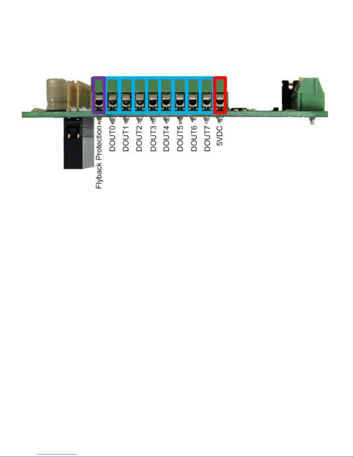
Refer to the diagram at the top of this page as well as the one below to locate the Digital Output terminals:
Specifications
● Each of the 8 Digital Outputs is an open drain transistor
● Maximum sink current is 3A
● Maximum load voltage is 30VDC
● On voltage is typically less than 50mV with a load current of 1A
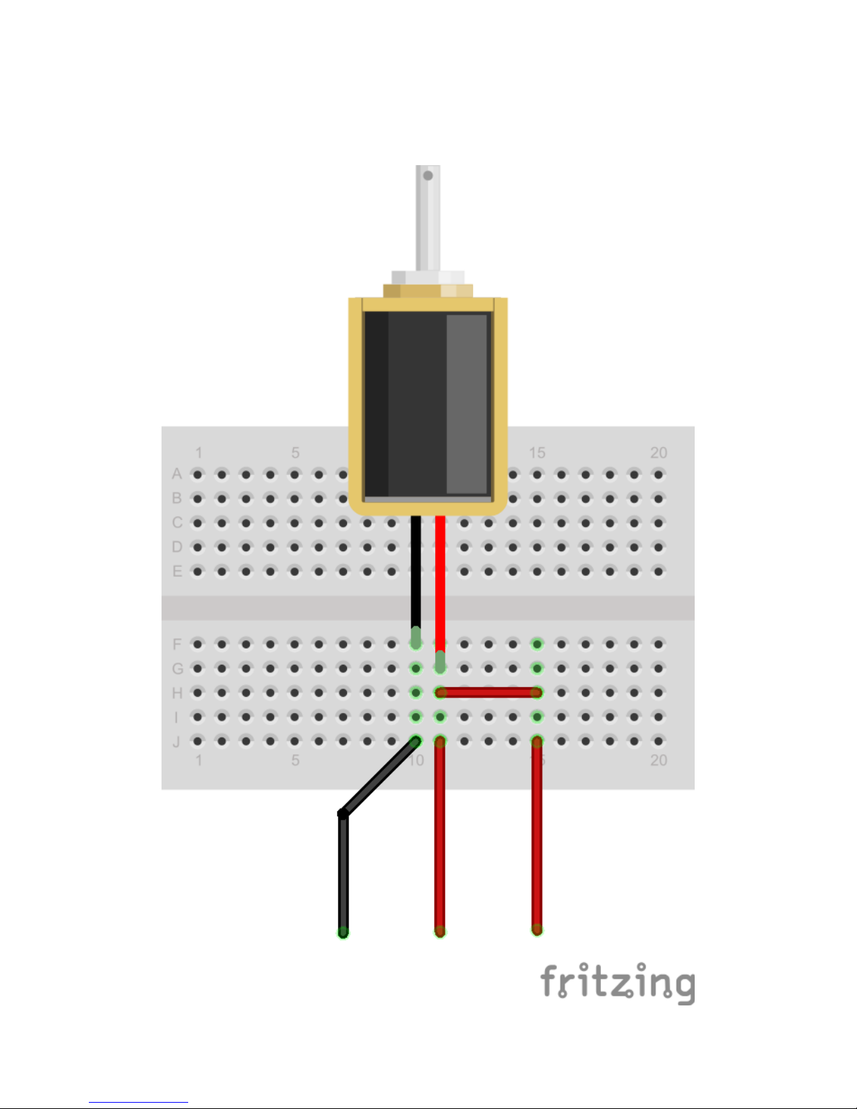
● When using a relay or solenoid, the high side power supply should be connected to the "Flyback
Protection" terminal
● If necessary, the on-board 5VDC is available on pin 10. If you choose to use it, then make sure your
power supply can provide enough current for your Raspberry Pi (~700mA), your Pi-Plates (~100mA for
each DAQC2plate with all LEDs on) and any components you connect to a DOUT terminal.
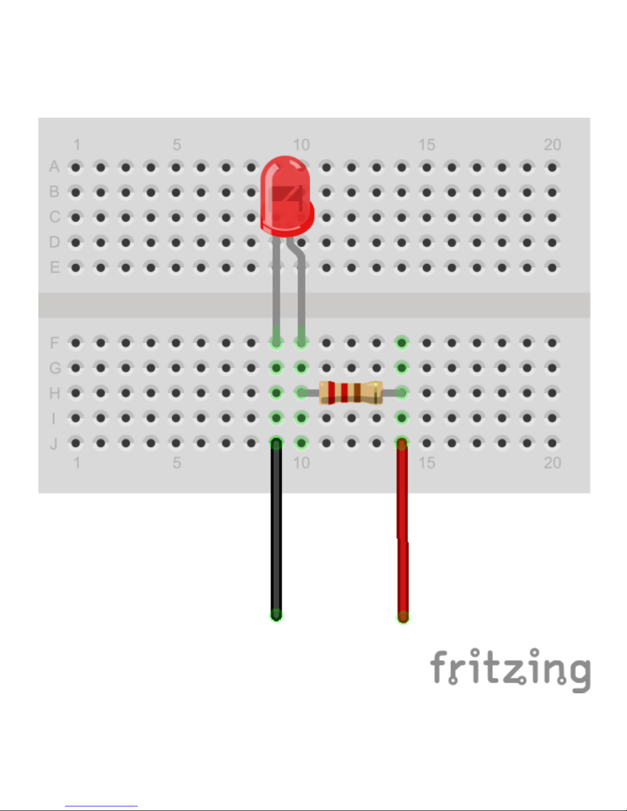
● To generate a simple digital signal output, connect a 4.7K resistor between 5VDC and the DOUT pin
you wish to use. Note that the output will be inverted i.e. setting the pin will make the output zero volts
while clearing it will make it 5VDC.
Functions
addr must be in the range of 0 through 7
bit must be in the range of 0 through 7
● setDOUTbit(addr, bit) - set single bit. Note that this turn ON the transistor and any device attached to it.
● clrDOUTbit(addr, bit) - clear single bit. Note that this turn OFF the transistor and any device attached to
it.
● toggleDOUTbit(addr, bit) - toggle a single bit
● setDOUTall(addr,byte) - control all eight bits at once. The byte value must be in the range of 0 through
255.

Examples
Simple External LED
Use a simple breadboard to build up this LED circuit. Connect the anode of the LED (the long wire) to one end
of a 220 ohm resistor. Route a red wire from the other side of the resistor to the 5VDC terminal on the
DAQC2plate digital output terminal block. Route a black wire from the cathode of the LED to Output 0 of the

terminal block. Assuming the DAQC2plate board is at address 0, type DAQC2.setDOUTbit(0,0) to turn the LED
on. Type DAQC2.clrDOUTbit(0,0) to turn off the LED.
A Short String of White LEDs
Control some under-counter lighting with this circuit. Connect three, high-bright white LEDs in series as shown
and then attach a 12VDC power supply with a center-positive connector. Then put a 100 ohm resistor between
the LEDs and the power supply. Attach the cathode of the rightmost LED to DOUT0 of the terminal block (pin

1) and the ground of the power supply to pin 9 or 10 on the DIN terminal block. Again, assuming the
DAQC2plate board is at address 0, type DAQC2.setDOUTbit(0,0) to turn the LED string on. Type
DAQC2.clrDOUTbit(0,0) to turn off the LED string.
Driving an Inductive Load
1. Use a simple breadboard to build up this 5V solenoid circuit.
2. Connect the red wire from the solenoid to a pair of red wires that route from the breadboard.

3. Attach one of these to the 5VDC terminal on the DAQC2plate digital output terminal block.
4. Connect the other red wire to the Flyback Protection terminal. Route a black wire to DOUT0 of the
terminal block.
5. Assuming the DAQC2plate board is at address 0, type DAQC2.setDOUTbit(0,0) to turn the solenoid on.
6. Type DAQC2.clrDOUTbit(0,0) to turn off the solenoid.
Analog Inputs (ADC)
Use the analog input to measure sensors that produce a variable output voltage. These eight terminals can be
used for measuring voltage, temperature, humidity, light brightness, potentiometers, strain gauges, and much
more.
Connector
Refer to the diagram at the top of this page as well as the one below to locate the Analog Input terminals:
Specifications
● Eight inputs
● 16 bit resolution (16 bits is obtained by averaging 128 fourteen bit values)
● ~366μV per bit
● Maximum input voltage range: ±12 volts
● >0.1% precision
● SNR of 75dB with a 10VDC input voltage
● All inputs have ESD protection
● All inputs have over and undervoltage protection
● Bandwidth of each input is limited to 50Khz to minimize high frequency noise.
● All inputs are factory calibrated
● Note that a floating input will read 1.333 volts.
● Dedicated input (channel 8) for measuring power supply voltage (accurate to ±1.5%)
Functions
addr must be in the range of 0 through 7
channel must be in the range of 0 through 8
● getADC(addr, channel) - return voltage from single channel. Reading channel 8 will return the 5VDC
power supply voltage.

● getADCall(addr) - return an 8 element list of floating point values with voltages from all eight input
channels
Examples
Using a Potentiometer to Generate a Variable Voltage
1. Attach a 10K potentiometer to a protoboard as shown on the left side of the diagram below.
2. Route the red wire to the 5VDC terminals (terminal 10) on the Analog Input Block
3. Route the black wire to the ground terminal on the Analog Input Block (terminal 9)
4. Route the yellow wire to Analog Input 0 on the Analog Input Block (terminal 1)
5. Go into the Python interactive environment and import the DAQC2plate module by typing import
piplates.DAQC2plate as DAQC2
6. Assuming a DAQC2plate board address of 0, type DAQC2.getADC(0,0) from the command prompt and
look at the returned value
7. Rotate the "pot" and retype DAQC2.getADC(0,0). Turning the "pot" completely clockwise will return a
value of around zero volts. Turning the "pot" completely counter clockwise will return a value of 5 volts.

Measure Temperature Using an LM35 Sensor
1. Attach an LM35 temperature sensor to a protoboard as shown on the right side of the diagram above.
2. Route the red wire to the 5VDC pin (terminal 9) on the Analog Input Block
3. Route the black wire to the ground terminal on the Analog Input Block (terminal 10)
4. Route the yellow wire to Analog Input 0 on the Analog Input Block (terminal 1)
5. Go into the Python interactive environment and import the DAQC2plate module by typing import
piplates.DAQC2plate as DAQC2
6. Assuming a DAQC2plate board address of 0, type DAQC2.getADC(0,0) from the command prompt and
look at the returned value. The LM35 will return a voltage that is proportional to the temperature in
degrees Celsius: 10mV = 1 degree C. If you are performing this experiment inside then the
DAQC2plate measurement should return a value of about 250mV for a temperature of 25C.
7. For more information about the LM35, go here .
Digital Inputs (DIN)
Use the digital inputs to detect simple on-off devices such as buttons, rotary encoders, and the output of
another microcontroller such as an Arduino board.
Connector
Refer to the diagram at the top of this page as well as the one below to locate the Digital Input terminals:
Specifications
● All inputs have ESD protection
● All inputs have over and undervoltage protection
● All inputs have built-in pull up resistors for simple attachment of switches and outputs from optical
sensors
● Compatible with 3.3 and 5V logic
● All inputs capable of triggering an interrupt to the Raspberry Pi

Functions
addr must be in the range of 0 through 7
bit must be in the range of 0 through 7
● getDINbit(addr,bit) - return single bit value
● getDINall(addr) - return all eight bits
● enableDINint(addr, bit, edge) - enable interrupts for an input change on the specified bit. The "edge"
value can be 'r' for rising, 'f' for falling, of 'b' for both.
● disableDINint(addr,bit) - disable interrupts on the specified bit
Example: Monitor an External Button
With a built in pull up resistors, monitoring buttons and switches with the Digital Inputs of the DAQC2plate is
simple:
1. Attach a normally open push button to a protoboard as shown below
2. Route the yellow wire to Digital Input 0 on the Digital Input Block (terminal 1)
3. Route the black wire to a ground terminal on the Digital Input Block (terminal 9 or 10)
4. Go into the Python interactive environment and import the DAQC2plate module by typing import
piplates.DAQC2plate as DAQC2
5. Assuming a DAQC2plate board address of 0, type DAQC2.getDINbit(0,0) from the command prompt
and look at the returned value. The DAQC2plate should return a value of 1 since the button is up and
the input voltage is 5VDC.
6. While pushing the button, execute DAQC2.getDINbit(0,0) from the command prompt again. This time
the DAQC2plate should have returned a value of 0 since pressing the button grounds the input.
Extended Functions

The Extended Function Block provides four additional additional features to the DAQC2plate. These include:
1. Four calibrated 12 bit digital to analog converter outputs. These can be used for a number of functions
and, when used in the Function Generator Mode, are fast enough to generate common waveforms
such as sine, square, and triangle.
2. An auxiliary 5VDC power input. If your project requires more current than your RPi supply can provide
or if you want a guaranteed clean source of power, attach your supply to this pair of connectors.
3. A frequency counter - this protected input will measure the frequency of any digital signal.
4. Two PWM outputs - these 10 bit resolution PWMs output a 5V digital waveform and can be set from 0
to 100%. Very useful for DC motor and fan speed control.
Connector
Refer to the diagram at the top of this page as well as the one below to locate the terminals for each of the
Extended Functions:
Analog Outputs (DAC)
These outputs are on pins 1-4 of the Extended Function Block.
Specifications
● ESD protected
● Output swing of 0 4.095 volts
● 12 bit resolution
● Calibrated at factory for 0.2% accuracy using 3 point regression
● Resolution of 1mV
● Output noise of 110 μV rms
● Slew rate of 1 V/μs
● Nonlinearity of ±2 LSB
Functions

addr must be in the range of 0 through 7
channel must be in the range of 0 through 3
● setDAC(addr,channel,value) - set DAC output voltage from 0 to 4.095 volts.
● getDAC(addr,channel) - return current DAC output voltage. Returned value will be between 0 and 4.095
volts.
Auxiliary Power Supply
The DAQC2plate has a pair of terminals on the Extended Functions block that allow the use of a high quality
power supply. Reasons you may want to use this feature include:
● You plan to stack a lot of Pi-Plates
● You need more power for your digital output loads
● You plan to operate the DAQC2plate in Motor Controller mode and want to use 5VDC stepper motors
There are a few rules when using this input:
1. It can't be used with a power supply plugged into the RPI. Well, it -can- but it won't buy you anything
and we can't guarantee it will work with future versions of the Raspberry Pi.
2. Do not exceed four amps of current - the reverse bias protection circuitry will not like it.
3. Be sure to use a high quality supply with internal fusing. A UL or ETL mark is a good indicator of this.
4. If you use more than one DAQC2plate or DAQCplate in your stack, only one can be used for providing
Auxiliary Power. By design, accidentally hooking up multiple supplies on multiple DAQCplate boards
should not cause any damage but, only one of the supplies will be providing current.
Usage
1. Power down your stack and unplug the power supply currently attached to your Raspberry Pi.
2. Referring to the image below, loosen the screws on terminals 6 and 7 on the Extended Function Block
3. Noting the polarity, push the positive and negative wires of your power supply into the AUX 5VDC IN
and Ground terminals and tighten the screws. Don't worry if you accidentally connect it backwards - the
reverse bias protection circuit will prevent any damage.
4. Plug in your power supply and start coding!
PWM
These two outputs are located on pins 9 and 10 of the Extended Functions block.
Specifications
● All outputs have ESD Protection
● 10 bit resolution
● Oscillator frequency of 15.9Khz
● Output swings from 0 to 5VDC - note that this output is unregulated
Functions
addr must be in the range of 0 through 7
channel must be a value of 0 or 1
value is a floating point number that can range from 0.0 to 100.0
● setPWM(addr,channel,value) - set PWM signal from 0 to 100%
● getPWM(addr,channel) - return current PWM setting. Returned value will be a number between 0 and
1023.

Example - Speed Control of a DC Motor
This example assumes that you have a small DC motor that operates at 5VDC max and pulls less than 1 Amp:
1. Attach the motor, a 1K resistor, a PN2222 NPN transistor, and the wiring to the protoboard as shown in
the diagram above.
2. Route the red wire to the 5VDC terminal (pin 10) on the Digital Output Block
3. Route the black wire to a ground terminal on the Extended Functions block (terminal 4 or 5)

4. Route the yellow wire to PWM Output 0 on the Extended Functions block (terminal 10)
5. Go into the Python interactive environment and import the DAQC2plate module by typing import
piplates.DAQC2plate as DAQC2
6. Assuming a DAQC2plate address of 0, type DAQC2.setPWM(0,0,50.0) to set the motor to
approximately half speed.
Frequency Counter
The DAQC2plate has an input dedicated to measuring the frequency of any ground referenced signal with a
amplitude in the range 3.3 to 5 volts. This can be used for simple bench measurements or as a tachometer for
a DC motor.
Specifications
● Input Range: ground referenced signal can range from 3.3 to 5VDC.
● Measurable Frequency Range: ~ 1.00 to 150Khz
● Accuracy: ±2%
● Input Hysteresis: 1.3V
Functions
getFREQ(addr) - returns the frequency of the attached signal as an integer value.
RGB LED
Each DAQC2plate has a general purpose RGB LED. At power up, this LED is set to white to indicate a
successful hardware initialization. However, you can use the LED functions below to change the color as you
see fit for your application.
Functions
addr must be in the range of 0 through 7
color values is a string that can be set to the following:
1. 'off'
2. 'red'
3. 'green'
4. 'yellow'
5. 'blue'
6. 'magenta'
7. 'cyan'
8. 'white'
● setLED(addr,color) - turn on one of the LEDs in the bicolor LED package
● getLED(addr) - returns a string value with the current LED color
Interrupts

For detecting asynchronous events such as changes on the Digital Input terminals, the DAQC2plate supports
the use of interrupts. An excellent tutorial on how to use interrupts in Python can be found here . Note that all
Pi-Plates use the GPIO22 pin on the Raspberry Pi for generating an interrupt. If you don't choose to use
interrupts, GPIO22 is available for your applications.
Functions
General
addr must be in the range of 0 through 7
● intEnable(addr) - enable interrupts from the DAQC2plate. GPIO22 will be pulled low if an enabled event
occurs.
● intDisable(addr) - disables and clears all interrupts on the DAQC2plate
● getINTflags(addr) - returns 16 bit flag value and clears all INT flags
The interrupt flag register mapping looks like:
The bit definitions are:
● DIN0: set when a transition occurs on DIN0 that set by the enableDINint function described below.
● DIN1: set when a transition occurs on DIN1 that set by the enableDINint function described below.
● DIN2: set when a transition occurs on DIN2 that set by the enableDINint function described below.
● DIN3: set when a transition occurs on DIN3 that set by the enableDINint function described below.
● DIN4: set when a transition occurs on DIN4 that set by the enableDINint function described below.
● DIN5: set when a transition occurs on DIN5 that set by the enableDINint function described below.
● DIN6: set when a transition occurs on DIN6 that set by the enableDINint function described below.
● DIN7: set when a transition occurs on DIN7 that set by the enableDINint function described below.
● A2D: not used at this time
● Oscope: used in oscilloscope mode to signal the end of a sweep
● MOTOR 1 STOPPED: when enabled in the Motor Controller Mode, signals when stepper motor 1 has
completed a MOVE operation
● MOTOR 2 STOPPED: when enabled in the Motor Controller Mode, signals when stepper motor 2 has
completed a MOVE operation
● N/A: Not Assigned
● N/A: Not Assigned
● N/A: Not Assigned
● N/A: Not Assigned
Digital Input
The following functions control interrupt generation on the Digital inputs:
addr must be in the range of 0 through 7
bit must be a value between 0 and 7

● enableDINint(addr, bit, edge) - enable interrupts for an input change on the specified bit. The "edge" is
a string value that is 'r' for rising, 'f' for falling, of 'b' for both.
● disableDINint(addr,bit) - disable interrupts on the specified bit
Special Modes
The DAQC2plate can be operated in 4 specific modes:
1. Legacy (all of the functions described in the sections above)
2. Motor Controller
3. Function Generator
4. Oscilloscope
Installing the Applications
Applications with graphical user interfaces have been developed for each of these modes. To install them,
open a terminal window inside your home directory and perform the following steps:
1. If you haven't already done so: sudo pip install Pi-Plates
2. If you haven't already done so: sudo pip3 install Pi-Plates
3. Install the Python-QT routines: sudo apt-get install python3-pyqt4
4. Download the apps and the documentation: sudo wget
https://pi-plates.com/downloads/DAQC2apps.tar.gz
5. Expand the archive: tar -xzvf DAQC2apps.tar.gz
6. After the files have been unpacked, delete the archive with: rm DAQC2apps.tar.gz
We know that's a lot of steps and we soon hope to have a script that will automate it with a pip command. But,
when when you're done, you should have a nice set of shortcuts on the left side of your screen:
Table of contents
Popular Motherboard manuals by other brands

ASROCK
ASROCK X99M Extreme4 user guide

Supermicro
Supermicro P3TDER Plus quick start guide

Lattice Semiconductor
Lattice Semiconductor ispMACH 4000ZE Pico user guide

SK Pang Electronics
SK Pang Electronics RSP-PICAN3 user guide

Linear Technology
Linear Technology LTC2351-14 Quic Start Guide

Supermicro
Supermicro X12SCV-W user manual