pietranera 507 User manual

TRESOR MODULO
WASH UNIT
INSTRUCTIONS FOR INSTALLATION, USE AND
ROUTINE MAINTENANCE
507_507P_507M

2
CONTENTS
INTRODUCTION .............................................................................................................................................................3
PREREQUISITES ................................................................................................................................................................4
INTENDED USE ................................................................................................................................................................4
INSTRUCTIONS FOR USE ...........................................................................................................................................4
DEFINITION .......................................................................................................................................................................4
SAFETY ...............................................................................................................................................................................4
ELECTRICAL SPECIFICATIONS ....................................................................................................................................5
MIXER SPECIFICATIONS ...............................................................................................................................................5
THERMOSTATIC MIXER SPECIFICATIONS ...........................................................................................................5
TRANSPORT AND STORAGE ..................................................................................................................................... 6
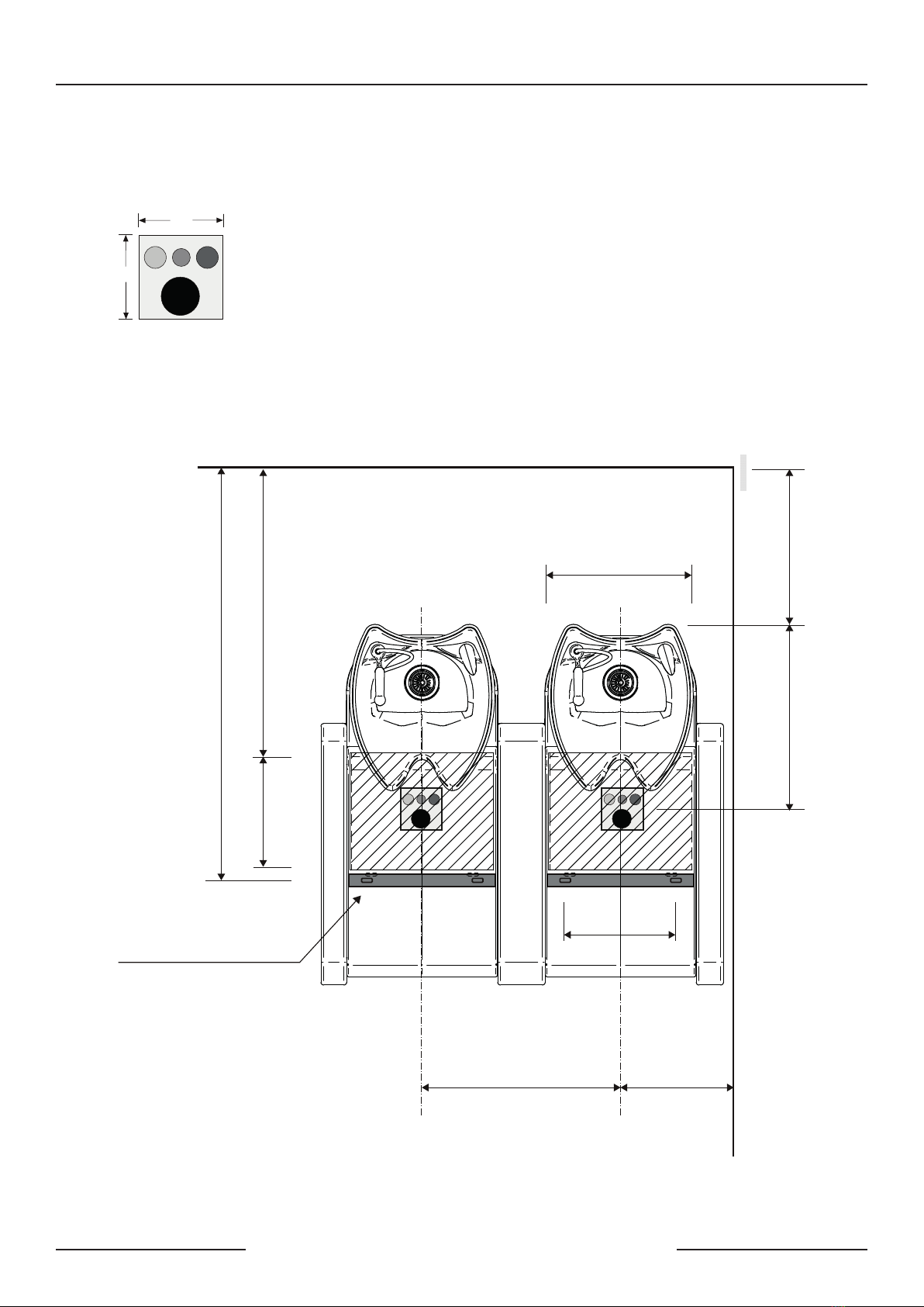
DIMENSIONS ....................................................................................................................................................................6
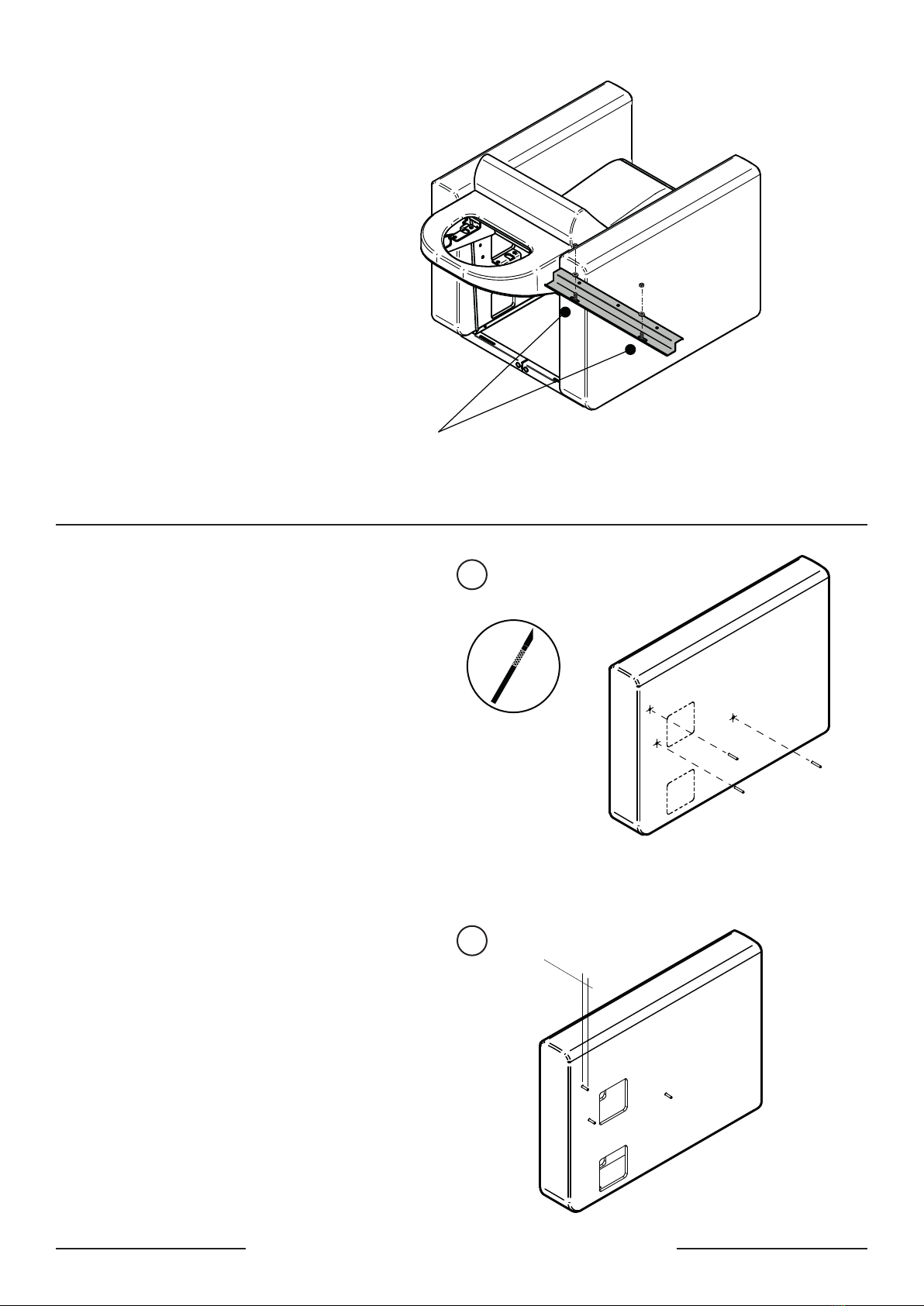
INSTALLATION SURFACE ..............................................................................................................................................7
PREPARATION ..................................................................................................................................................................9
WASH UNIT ATTACHMENT ........................................................................................................................................9
BASIN ASSEMBLY .........................................................................................................................................................10
DRAIN ASSEMBLY ........................................................................................................................................................12
FLOOR DRAIN ...............................................................................................................................................................13
WALL DRAIN ..................................................................................................................................................................14
ELECTRICAL CONNECTION ........................................................................................................................................15
TESTING ...........................................................................................................................................................................16
USE .....................................................................................................................................................................................16
SWITCHING ON THE EQUIPMENT .........................................................................................................................16
RELAX CONTROLS ........................................................................................................................................................17
JET MASSAGE CONTROLS .........................................................................................................................................18
ROUTINE MAINTENANCE ..........................................................................................................................................19
CHAIR ...............................................................................................................................................................................19
WASHBASIN UNIT .........................................................................................................................................................20
CLEANING THE SURFACES .........................................................................................................................................20
ELECTRICAL FUNCTIONS ........................................................................................................................................21
IDENTIFICATION OF THE EQUIPMENT ................................................................................................................21
INSTRUCTIONS FOR DISPOSAL .............................................................................................................................21
Instructions for Installation, Use and Maintenance

3
INTRODUCTION
Instructions for Installation, Use and Maintenance
Thank you for purchasing a Pietranera product. We are certain you will be fully satised with your
choice.
Pietranera products are manufactured according to strict quality standards using only the best compo-
nents.
The operation and safety of each wash unit were tested in painstaking detail before shipment.
Check that the wash unit was not damaged during transport in a manner that could impair its operation
and safety.
You are advised to follow the instructions contained in this manual carefully for the best reliability, long
life and top-notch performance of the wash unit.
The manual is designed to allow you to use the wash unit in the best and safest manner.
Therefore, this manual is an integral part of the wash unit. It must be kept carefully throughout the dura-
tion of the wash unit and accompany the wash unit if it is transferred to a new user.
To avoid problems, read this manual carefully before carrying out any operation on the wash unit and
follow the instructions scrupulously.
The manufacturer accepts no liability for damage caused by negligence and/or failure to observe the
instructions in this manual.
Without prejudice to the main technical and safety features of the product, the manufacturer reserves
the right to make changes to the wash unit for reasons of continual technical and technological evolu-
tion without prior notice, without incurring any penalty.
The partial or total reproduction of this manual, including texts and illustrations, is prohibited by law.
The Court of Reggio Emilia (Italy) is competent in case of disputes.

4
PREREQUISITES
The wash unit chair is intended for professional use in hair treatment salons, particularly in the hair
washing area.
INTENDED USE
INSTRUCTIONS FOR USE
DEFINITIONS
The equipment complies with the essential European Union regulations on ergonomics
and safety. The manufacturer guarantees these qualities by axing the CE marking.
SAFETY
The following requirements must be observed for a correct and safe installation of the equipment:
1) The oor must comply with DIN 1055 B 1.3 and DIN 18560 T 1.
2) The electrical system must comply with CEI 64.4 standards, using 250V/16A dierential protection
conductors (<30mA).
3) Do not connect devices that are not specied as part of the system.
4) Earthing, in particular, must comply with Article 3.2.01 of the aforementioned standards.
5) The equipment must be xed to the oor using anchor bolts with a minimum diameter of 8 mm.
The manufacturer is not liable for the safety and reliability of the equipment if:
• installation and repairs are not carried out by authorised technicians
• the general and electrical installation of the room does not comply with the requirements
indicated above
• the device was not installed following this manual
• the device is not used following this manual.
The wash unit chair is intended for professional use in hair treatment salons, particularly in the hair
washing area. It cannot be used by more than one operator at the same time and can accommodate only
one customer at a time. The maximum load capacity is 120 kg. The equipment must be xed to the oor.
The installation is compliant if carried out according to the specications indicated in the Installation,
Use and Maintenance Manual. The equipment must be xed with anchor bolts with a minimum diameter
of 8 mm. Sitting on the worktops and armrests is not permitted. Multiple people are not allowed to sit
together. It is not allowed to get seated and/or get up while the footrest is moving or if the chair being
raised.
Beware of scalding caused by hot water.
Beware of moving parts of the wash unit chair.
Hairdresser, or operator, is the person who performs the treatment of the customer's hair and who man-
ages the operation of the wash unit chair. The workstation is situated at the back of the wash unit chair.
Customer is the person who is receiving the hair treatment. The front part of the wash unit chair is used
to seat the customer.
Instructions for Installation, Use and Maintenance

5
ELECTRICAL SPECIFICATIONS
Wash unit model
TRESOR MODULO Jet Massage
Electric TRESOR MODULO Relax
Rated
voltage
220V ~ ±10%
220V ~ ±10%
Rated
frequency
50/60 Hz
50/60 Hz
Rated power
220VA
250VA
Intermittent
operating mode
3 min. ON
5 min. OFF
8 min. ON
5 min. OFF
MIXER SPECIFICATIONS
Code 507P
Code 507M
Technical specications
Test pressure 15 bar
Cold water supply blue indicator pointing rightwards. Pipe connection 3/8″
Hot water supply red indicator pointing leftwards. Pipe connection 3/8″
Limits of use according to UNI 10234 EN (817):
MIN. pressure 0.5 bar MAX. 10 bar (100000000 pascals)
MAX. temperature 90°
Limits of use recommended by UNI 10234 (EN 817) for a good tap operation
Pressure: MIN. 0.5 bar MAX. 5 bar (50000000 pascals)
Temperature: MAX. 65°C
Warnings:
- The system pipes must be carefully rinsed to avoid damage to the taps caused by any residues in the
pipes.
- It is recommended to install a pressure reducer in case of operating pressures above 5 bar.
- It is also recommended to install a central lter for water with a high impurity content.
Technical specications
Test pressure 15 bar
Cold water supply blue indicator pointing rightwards. 1/2" pipe connection
Hot water supply red indicator pointing leftwards. 1/2" pipe connection
Limits of use according to UNI 10234 EN (817):
MIN. pressure 1 bar MAX. 10 bar (100000000 pascals)
MAX. temperature 90°
Limits of use recommended by UNI 10234 (EN 817) for a good tap operation
Pressure: MIN. 1 bar MAX. 5 bar (50000000 pascals)
Temperature: MAX. 65°C
Warnings:
- The system pipes must be carefully rinsed to avoid damage to the taps caused by any residues in the
pipes.
- It is recommended to install a pressure reducer in case of operating pressures above 5 bar.
- It is also recommended to install a central lter for water with a high impurity content.
THERMOSTATIC MIXER SPECIFICATIONS
Instructions for Installation, Use and Maintenance

6
DIMENSIONS
The packages must be transported on closed vehicles. Do not drop or tilt packages during loading and
unloading. The products must be stored in a dry, indoor place, stacking up to three packages on top of
each other and without drastic temperature changes.
Environmental conditions for transport and storage
• Ambient temperature from -25°C to +50°C.
• Relative humidity max 75%.
Environmental conditions of use
• Ambient temperature from +10°C to +40°C.
• Relative humidity from 30% to 75%.
TRANSPORT AND STORAGE
Dimensions in mm.
Instructions for Installation, Use and Maintenance
520
980
1300
1570 ( length with footrest )
70 140 520 70

7
10
10
10
10
1 2
3
4
WARNING: Open the side panel before xing the wash unit in a side-by-side arrangement with a side
drain.
INSTALLATION SURFACE
Plant layout
1 = Hot 3/8" (1/2" thermostatic mixer)
2 = Cold 3/8" (1/2" thermostatic mixer)
3 = ø 40 mm drain
4 = Electrical cable outlet (where required)
Cord 3X1 (1500 mm) - 220/240 V - 50 Hz/60 Hz
Important note The grey areas delimit the space available for installation.
Instructions for Installation, Use and Maintenance
1 2
3
4
1 2
3
4
min. 1050400
490
350
min. 600 640
1460
N°2 fixing slots
10x40 mm
660 390

8
INSTALLATION SURFACE
1 = Determine the height of the wall drain from the ground.
2 = Open the rear wash unit casing.
3 = Locate the pre-existing slot on the inside of the shoulder and drill a centring hole at the
detected height.
4 = Fix the supplied ange with the appropriate screws on the outside of the shoulder.
5 = Open the side panel.
INSTRUCTIONS
Dimensions in mm.
Instructions for Installation, Use and Maintenance
130
390
min. 600 min. 560
120
120

9
Preparation
1) Remove the packaging leaving the wash unit mounted on the pallet so that it is easier to transport.
Remove the wash unit protections and any accessories contained in the packaging itself.
2) Position the wash unit and mark the xing points (Fig. 2). Drill holes for the anchor bolts.
Fixing the wash unit
WARNING: Prepare the holes for the drain and electrical power supply, if applicable before xing
the wash units, either in side-by-side arrangement or with side drain.
INSTALLATION
1) Undo the screws (1) fastening
the rear casing.
2) Undo the two screws xing the
wash unit to the pallet (2) and
position the wash unit in the spot
prepared for installation.
Instructions for Installation, Use and Maintenance
2 (X2)
1 ( X2 )

10
3) Place the two nylon discs supplied
(1) under the base of the wash unit
and x it to the oor with the anchor
bolts suitable for the type of material
of which the oor is made using the
four holes provided for the purpose.
Instructions for Installation, Use and Maintenance
SIDE ARMREST ASSEMBLY
1 - Use a cutter to open the existing
slots for a possible side installation.
2 - Insert the M8 dowels into the holes
drilled in the armrest until an external
height of 30 mm is reached.
3 - Insert the shoulder into the
armchair module and tighten the nuts
with washer.
4 - Repeat steps 1-2-3 for each armrest
to be mounted.
1
2
2 (X2)
30 mm

11
Instructions for Installation, Use and Maintenance
CENTRAL ARMREST ASSEMBLY
1 - Use a cutter to open the existing
slots for lateral installation on both
sides of the middle armrest.
2 - Insert the M8 dowels into the holes
drilled in the armrest until an external
height of 30 mm is reached.
3 - Assemble the central armrest to the
armchair module and tighten the nuts
with washers.
4 -Repeat all the steps for each inter-
mediate armrest to be assembled.
1
2
30 mm

12 Instructions for Installation, Use and Maintenance
3
BASIN ASSEMBLY
1) Place the basin (1) over the column.
Carefully tightening the 4 screw nut.
1

13
Instructions for Installation, Use and Maintenance
2) Get the mixer body tubes through the
collar.
3) Tighten the longest exible tube of
the mixer unit to the fork.
4) Tighten all the components.

14
DRAIN ASSEMBLY
Mount the drain onto the washbasin
As shown in the gure.
1) Grid
2) Tightening screw
3) Stainless steel drain body
4) Plastering
5) Washbasin
6) Gasket
7) Draining cup
8) OR Gasket
9) Extensible - exible drainage pipe
Min 430 - Max 1300 mm
Instructions for Installation, Use and Maintenance
1
2
3
4
5
6
7
8
9

15
10
10
10
10
1 2
3
4
Floor drain
WARNING:
The water connection may only be carried out by qualied technicians
Open the side panel (Point 2) if the installation requires infeed of the power supply from the wall or in a
side-by-side arrangement.
1) Install the water unit using ø 3/8" hydraulic connections (1/2" if thermostatic). It is advisable to provide
a gate valve upstream of each tting.
Connections to the sewage system are established using a ø 40 drain pipe.
INSTALLATION
Plant layout
1 = Hot 3/8”
2 = Cold 3/8”
3 = ø 40 mm drain
4 = Electrical cable outlet (where required)
Cord 3X1 (1500 mm) - 220/240 V - 50 Hz/60 Hz
2) Opening the side panel
1 = Determine the height of the wall drain from the ground
2 = Open the rear wash unit casing.
3 = Locate the pre-existing slot on the inside of the shoulder and drill a centring hole at the detected
height.
4 = Fix the supplied ange with the appropriate screws on the outside of the shoulder.
5 = Open the side panel
Instructions for Installation, Use and Maintenance
Preparation for water
connection

16
INSTALLATION
Wall drain
WARNING:
The water connection may only be carried out by qualied technicians
Open the side panel if the installation requires a power supply inlet from the wall or in a side-by-side
arrangement.
1) Opening the side panel
1 = Determine the height of the wall drain from the ground
2 = Open the rear wash unit casing.
3 = Locate the pre-existing slot on the inside of the shoulder and drill a centring hole at the measured
height.
4 = Fix the supplied ange with the appropriate screws on the outside of the shoulder.
5 = Open the side panel.
2) Install the water unit using ø 3/8” hydraulic connections (1/2” if optional thermostatic). It is advisable to
provide a gate valve upstream of each tting.
Connections to the sewage system are established using a ø 40 drain pipe.
10
10
10
10
1 2
3
4
Plant layout
1 = Hot 3/8”
2 = Cold 3/8”
3 = ø 40 mm drain
4 = Electrical cable outlet (where required)
Cord 3X1 (1500 mm) - 220/240 V - 50 Hz/60 Hz
Instructions for Installation, Use and Maintenance
Preparation for water
connection

17
ELECTRICAL CONNECTION
( g. 1 ) ( g. 2 )
3) WARNING: The seat can move on some models. Make sure that the cables are not pulled (or can be
pulled when the seat is moved) when connecting the wash unit. Also, make sure that they are not close
to moving mechanisms.
WARNING:
The electrical connection may only be carried out by qualied technicians
Check that the electrical system complies with Points 2 and 4 of the PREREQUISITES on page 4.
It is advisable to provide an automatic switch and disconnector to cut o power to the wash units at any
time.
1) The wash unit models that require an electrical power supply are equipped with a 3x1, 1.5 m long cord
with a Schuko plug. Plug it into the socket.
2) By opening the junction box (g. 1) of the wash unit, it is possible to connect the mains wires directly
to the terminal board N L (g.2).
Instructions for Installation, Use and Maintenance
N L
Bl Br
G-V
2
1
Electrical Relax
2
1
3
Jet massage
1 = Junction box 2 = Control box 3 = Compressor

18
TESTING
1) After testing, reposition the rear casing
using the screws (1).
Switching on the wash unit
The wash unit is switched on by plugging it into the power supply.
USE
Once the connection has been established, test all the functions of the equipment, preferably with a
person sitting in the chair:
- footrest all up
- footrest all down
- full cycle of the massage function
- cold water (mixer all open with the lever all to the left)
- hot water (mixer all open with the lever all to the right)
- drain (partially ll the basin, remove the cap and drain, repeat operation two or three times).
Instructions for Installation, Use and Maintenance
1 ( X2 )

19
Press the button to move the footrest down
Press the button to move the footrest up
Press the indicated pedal to move the footrest down
Press the indicated pedal to move the footrest up
Keypad for operating the electric footrest (1)
This keypad can be used to activate the device for adjusting the wash unit footrest.
Foot pedal (optional) for operating the electric footrest (2)
This foot pedal can be used to activate the device for adjusting the wash unit footrest.
RELAX CONTROLS
Relax control panel D6510060
Relax control pedal D5710030 ( Optional )
Instructions for Installation, Use and Maintenance

20
Press the button to turn the massage function on/o
Press the button to move the footrest up
Press the button to move the footrest down
LED indicator for massage in operation
Press the button to turn the massage function on/o
Press the button to move the footrest up
Press the button to move the footrest down
LED indicator for massage in operation
Keypad for operating the jet massage (1)
This keypad can be used to activate the device for adjusting the wash unit footrest and massage.
Foot pedal (optional) for operating the jet massage (2)
This foot pedal can be used to activate the device for adjusting the wash unit footrest and massage.
JET MASSAGE CONTROLS
Jet massage control panel C6420007
Jet massage control pedal G060040 ( Optional )
Instructions for Installation, Use and Maintenance
This manual suits for next models
2
Table of contents
Popular Washer manuals by other brands

Frigidaire
Frigidaire FTFB4000FS0 Error code chart

Whirlpool
Whirlpool Duet Steam WFW9750WW Energy guide

Fisher & Paykel
Fisher & Paykel CLEANSMART 7 Series INSTALLATION GUIDE/USER GUIDE

Hoover
Hoover WDXOC 575AC-AUS manual

Whirlpool
Whirlpool TWO SPEED AUTOMATIC WASHERS Use & care guide

AEG
AEG L6FBF60488 user manual