PIKA Harbor Plus SB15p User manual

M00017-02
Operations Manual
Pika Harbor Smart Battery
Harbor Flex / Harbor Plus
Part of the Pika Energy Island™

Harbor Smart Battery
Serial Number:
RCP Number:

1Harbor Smart Battery Operation Manual M00017-02
We are committed to quality and constant improvement. All specications and descriptions
contained in this document are veried to be accurate at the time of printing. However, we reserve
the right to make modications at any time that may result in a change of specication without
notice in our pursuit of quality. If you nd any inconsistencies or errors in this document, please
Check the resources tab at www.pika-energy.com for the latest specications and manuals.
© 11/21/17 Pika Energy, Inc. All rights reserved.
All information in this document is subject to copyright and other intellectual property rights of
Pika Energy, Inc. This material may not be modied, reproduced or copied, in whole or in part,
without the prior written permission of Pika Energy, Inc. and its licensors. Additional information
is available upon request.

2 Harbor Smart Battery Operation Manual M00017-02
Table of Contents
Section 1: Introduction 4
About this manual 4
Symbols used in this Manual 4
About the Harbor Smart Battery 5
Battery Modules 6
Section 2: Safety instructions 7
General Warnings 7
Safety Shutdown 8
Battery Modules 8
Section 3: Operation and Controls 10
Communication 10
System Operational Modes 10
Battery State of Charge (SOC) Setpoints 11
User Interface 13
Section 4: Powering the Nanogrid Without Utility Power 15
Islanding 15
Power Search 15
Blackstart 16
Service and Maintenance Instructions 18
Annual Inspection and Maintenance 18
Service 19
End of Life 19
Section 6: Technical Reference 20
Section 7: Product Specications 21
Section 13: Notes 22

3Harbor Smart Battery Operation Manual M00017-02
Table of Contents

4 Harbor Smart Battery Operation Manual M00017-02
About this manual
Section 1: Introduction
About this manual
This Operation Manual provides instructions for the use, operation, and maintenance of the Pika
Harbor Series of smart batteries for simple, reliable energy storage with optional solar charging.
The Harbor Smart Battery is designed to house compatible lithium ion battery modules, and
connects directly to the Pika Islanding Inverter™ and other REbus™- compatible components of
the Pika Energy Island™ system from Pika Energy.
This Operation Manual includes full details on the use, operation, and maintenance of Harbor.
The companion document to this Operation Manual is the Harbor Installation Manual.
Please reference the Installation Manual for complete information on installing, wiring, and
commissioning the Harbor smart battery.
Symbols used in this Manual
WARNING: This indicates a fact or feature very important for the safety
of the user to prevent injury or death and/or which can cause serious
hardware damage if not applied appropriately.
CAUTION: Presents information to prevent damage to this product
EARTH GROUND SYMBOL

5Harbor Smart Battery Operation Manual M00017-02
Section 1: Introduction
About the Harbor Smart Battery
The Harbor Smart Battery is an easy-to-install energy storage device for efcient DC-coupled
performance. As a storage component of the Pika Energy Island, Harbor Smart Battery models
can be used for grid-connected solar applications such as self-supply, rate arbitrage and clean
backup power. Both the Harbor Flex™ and Harbor Plus™ models are designed to work seamlessly
with Pika Energy’s S2500 Series PV Link optimizers, and X7600 and X11400 Series Islanding
Inverters to form the Pika Energy Island system for grid-tie solar-plus-storage.
All Pika Energy products use the REbus™ 380VDC nanogrid to connect energy sources, storage,
loads and the grid. The REbus nanogrid automates the ow of power to enable plug-and-play
setup and operation of Pika Energy equipment. For more information about REbus, visit pika-
energy.com.
In the diagram below, a REbus compatible Pika Islanding Inverter is directly connected to PV Link
optimizers and high voltage energy storage on the DC (REbus) line, shown to the the left of the
inverter. To the right of the inverter are AC lines: 240VAC or 208VAC for grid and home loads, and
critical load support up to 50A.
Grid LoadsInverterBatterySolar
Fig 1. Example Energy Island

6 Harbor Smart Battery Operation Manual M00017-02
Battery Modules
Battery Modules
Harbor is designed to be used with Panasonic DCB-105 lithium ion battery modules. Do not
attempt to connect batteries of any other make or model to your Harbor Smart Battery, including
any other lithium ion battery, or any other type of battery.
WARNING: Use ONLY Panasonic DCB-105 lithium ion battery modules. DO
NOT CONNECT ANY OTHER BATTERY MODULES. DOING SO WILL VOID
THE WARRANTY AND MAY DAMAGE THE HARBOR SMART BATTERY.
Refer to the manufacturer’s documentation for information on the correct handling, storage, and
use of your battery modules.

7Harbor Smart Battery Operation Manual M00017-02
Section 2: Safety instructions
IMPORTANT SAFETY INSTRUCTIONS. SAVE THESE INSTRUCTIONS!
General Warnings
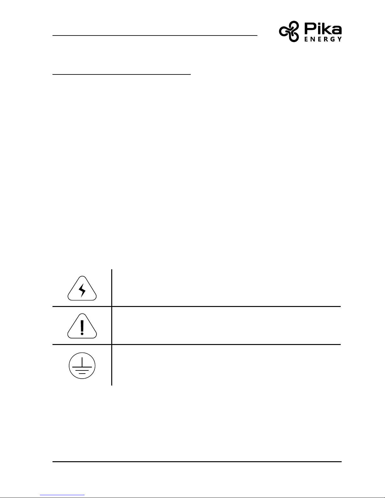
SHOCK RISK: HIGH VOLTAGE ELECTRICITY
WARNING: To reduce the risk of injury, read all instructions and caution
markings before installing Harbor. Consult installation documentation for
all other REbus devices on the system.
WARNING: Harbor must be installed by trained and qualied technicians,
and in accordance with all instructions.
WARNING: Electrical installation in the United States shall be done in
accordance with all local electrical codes and/or the National Electrical
Code (NEC), ANSI/NFPA 70.
WARNING: Electrical installation in Canada shall be done in accordance
with all local electrical codes and/or the Canadian Electrical Code.
WARNING: Connecting the Pika Energy Island to the electric utility
grid must only be done after receiving prior approval from the utility
company and installation completed only by qualied personnel/licensed
electrician(s).
WARNING: This equipment is NOT intended for use with life support
equipment or other medical equipment or devices.
WARNING: Protection against lightning surges in accordance with local
electric codes are the responsibility of the installer.
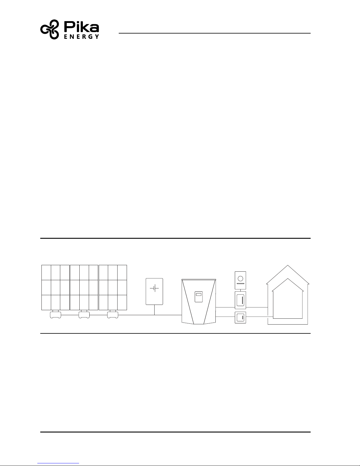
WARNING: Connect only to REbus-compatible devices. Never connect to
any other power source, including raw PV output, AC power, or any non-
REbus compatible battery.
WARNING: TURN BATTERY DISCONNECT TO “OFF” TO PREVENT
TERMINALS FROM ENERGIZING.

8 Harbor Smart Battery Operation Manual M00017-02
Safety Shutdown
Safety Shutdown
The Pika Energy Island system can signal to connected devices on REbus to shut down and limit
output voltage to a safe level. The red Safety Shutdown button on the front of Pika Islanding
Inverter activates a Safety Shutdown. An external shutdown button may also be installed, given
appropriate labeling. See the section titled “External Safety Shutdown Switch” in the Islanding
Inverter Installation manual.
To enter a Safety Shutdown, press and hold the red button on the front of the inverter. The
Safety Shutdown LED will illuminate and the LCD screen will indicate a Safety Shutdown has
been initiated.
In a system congured to provide backup power, the DC bus will remain energized on loss of AC
grid power. Upon entering a Safety Shutdown, a shutdown signal will be transmitted to all devices
connected to REbus. In Safety Shutdown, the Islanding Inverter will disconnect from the grid,
stop sourcing power to REbus, and immediately disable all sources on REbus by sending a global
shutdown signal. All PV Link optimizers will disconnect their output. The Safety Shutdown LED
will be illuminated to show that the inverter has entered a Safety Shutdown. DC bus voltage will
be displayed on the inverter screen.
WARNING: BEFORE PERFORMING SERVICE, ALWAYS INITIATE A SYSTEM-
WIDE SAFETY SHUTDOWN AND TURN THE FRONT PANEL BATTERY
DISCONNECT SWITCH TO “OFF” ON ALL CONNECTED SMART BATTERIES.
UNLESS THE BATTERY SWITCH IS “OFF”, THE BATTERY MAY PERFORM
A POWER SEARCH AT ANY TIME WHICH WILL CREATE DANGEROUS
VOLTAGE AT THE REBUS TERMINALS.
Battery Modules
Refer to the battery manufacturer’s documentation for warnings, hazards, and safe handling
instructions for your battery modules.

9Harbor Smart Battery Operation Manual M00017-02
Section 1: Introduction
WARNING: DO NOT ATTEMPT TO FIGHT A FIRE YOURSELF. EVACUATE THE
BUILDING AND CONTACT EMERGENCY SERVICES. Inform the dispatcher
that there are lithium-ion batteries in the building.
Keep a carbon dioxide or dry chemical re extinguisher near the battery location for use in
emergency by trained personnel only.
Emergency personnel: Refer to the manufacturer’s instructions and/or Safety Data Sheet for
complete information on re ghting.

10 Harbor Smart Battery Operation Manual M00017-02
Communication
Section 3: Operation and Controls
Communication
All communication between REbus devices takes place over the REbus conductors using Power
Line Carrier (PLC) communication. No additional communication wiring or equipment is required
for communication between a Harbor Smart Battery and the inverter, PV array, and/or other
REbus enabled smart batteries.
SunSpec Communications
The Harbor smart battery is capable of remote monitoring and control via a SunSpec interface.
Contact Pika Energy for more information on how to interact with Harbor via SunSpec.
System Operational Modes
The Pika Energy Island system has several operational modes available for various installation
congurations, markets, and applications. The Operational Mode is selected through the front
control panel of the Islanding Inverter. The Islanding Inverter prioritizes the distribution of
power differently based on the selected operational mode.
Refer to the Pika Islanding Inverter Installation and Operation Manuals for complete instructions
on conguring your entire system for each Operational Mode, including installing the inverter, CTs,
and transfer switches.

11Harbor Smart Battery Operation Manual M00017-02
Section 3: Operation and Controls
Battery State of Charge (SOC) Setpoints
There are four user-adjustable setpoints related to the battery state of charge (SOC). These
setpoints allow you to customize the behavior of your smart battery under different conditions.
The SOC is expressed as a percent (0% to 100%).
Max absolute
When the battery SOC is above this point, Harbor will not charge from any source. Default value is
100%.
Max arbitrage
When the battery SOC is above this point, Harbor is the lowest priority destination for power.
Harbor will charge only from PV power and only if all other higher priority loads are satised.
Default value is 100%.
Min arbitrage
When the battery SOC is below this point, Harbor is the lowest priority source of power on REbus.
Harbor will discharge only if there is no other source of power available. This will prevent the
system from operating in Self Supply until the battery SOC increases. If the grid goes out and
the system begins Islanding, then the battery will supply backup power normally. Default value is
50%.
If you lower this setpoint, you will have more battery capacity available for Self Supply and other
non-backup uses, but your guarnteed Islanding reserve will be smaller in the event of an outage. If
you raise this setpoint, you will have less capacity available for Self Supply and related modes, but
you can be sure of having more energy in your Islanding reserve in case of a grid outage.
Min absolute
When the battery SOC is below this point, Harbor shuts off and will not discharge further. If the
grid is present, then Harbor will charge as soon as power is available on REbus. If the grid is not
present and the system is Islanding, then Harbor goes to sleep and perofrms a Power Search
every 30 minutes. (See below for more information on Power Search.)
If you lower this setpoint, the system can provide more energy before it goes to sleep, potentially

12 Harbor Smart Battery Operation Manual M00017-02
Battery State of Charge (SOC) Setpoints
keeping the lights on for a longer time, but the Power Search reserve will be smaller. If you raise
this setpoint, the system may shut down sooner during an outage, but the Power Search reserve
will be larger.

13Harbor Smart Battery Operation Manual M00017-02
Section 3: Operation and Controls
User Interface
Inverter Control Panel
The Harbor is controlled through the front panel of your Islanding Inverter. Use the inverter to
enable or disable your smart battery, and to set the Operational Mode for your Energy Island
system. Once the system Operational Mode is selected, no additional conguration is necessary
for the correct operation of the Harbor.
Front On/Off Switch
There is a toggle switch on the front of the Harbor enclosure at the top left labeled “On” and “Off”.
This switch controls a set of internal relays which disconnect the battery string from the battery
monitoring system (BMS) electronics. Always initiate a Safety Shutdown from the inverter and
turn this switch to “Off” before servicing any part of the Pika Energy Island to prevent Harbor from
energizing the REbus Nanogrid. This switch may be locked in the “Off” position.
If the system will be powered down and left inactive for a long period of time, you may wish to
toggle the switch to the “Off” position to prevent discharge of the battery modules over time.
REbus Inverter
Internet
Shutdown
(hold)
X7601
Islanding Inverter
Rapid Shutdown
Select Button
REbus Indicator
Battery Icon LCD Display
Inverter Status
Network Status
Directional Pad
Inverter Model #
Inverter control panel

14 Harbor Smart Battery Operation Manual M00017-02
User Interface
Safety Shutdown Button
Before servicing any REbus equipment, always initiate a safety shutdown using the inverter
controls. If a lockable external Safety Shutdown switch is installed, then you may lock this switch
in the “Off” position.
LED
LED state Interpretation (strobe interval)
Green, 3 sec solid at powerup Enabled, operation starting
Red, 3 sec solid at powerup Disabled
Red/green, alternating Initializing, connecting battery and REbus, system energizing
Green, solid Enabled, charging
Green, strobe Enabled, standby (3 secs)
Green, ashing Enabled, discharging
Yellow, solid Waiting
Red, strobe Disabled (3 secs) / asleep (8 secs)
Red, ashing Error state

15Harbor Smart Battery Operation Manual M00017-02
Section 4: Powering the Nanogrid Without Utility Power
Section 4: Powering the Nanogrid Without Utili-
ty Power
Islanding
In the event of a grid outage, the Energy Island enters Islanding Mode: the Islanding Inverter
disconnects from the utility grid and powers the building from the REbus Nanogrid.
In a typical solar-plus-storage conguration, this means that all REbus-connected smart batteries
(including Harbor) will work together with the PV Links to supply power to REbus. The Inverter
will pull power off of REbus to provide AC power to the building.
Power Search
While the system is in Islanding Mode, Harbor may charge from PV power if there is plenty of
sunlight and not much load from the building. However, if Harbor provides power to the building
loads, then its State of Charge (SoC) will go down. Once the SoC reaches the Min Absolute
setpoint (described above), Harbor will enter a sleep state, the Islanding Inverter will shut down,
and the building will lose power.
While it is sleeping, the Harbor battery spends most of its time in a very low power state. Every 30
minutes, Harbor will perform a Power Search. During a Power Search, Harbor wakes up, energizes
the REbus Nanogrid to 380VDC and scans for potential sources of power. If there is another
source of power available, such as PV Link, then Harbor will begin charging. Once Harbor’s SOC
is 10% above the Min Absolute setpoint, it will supply power to the rest of the Nanogrid, allowing
the Inverter to operate in Islanding Mode.
However, if the Power Search does not discover any other sources of power, then Harbor will
return to sleep to conserve energy. The Power Search will maintain 380VDC on REbus for 60
seconds before Harbor returns to sleep.
Harbor can only perform a Power Search a certain number of times before it runs out of energy
completely; the number of scans available is dependent on the value of the Min Absolute
setpoint. Once Harbor depletes its Power Search reserve, it will not energize the REbus Nanogrid
on its own. Another source of power is necessary to energize REbus and charge the battery.

16 Harbor Smart Battery Operation Manual M00017-02
Blackstart
WARNING: DURING A POWER SEARCH, HARBOR CREATES DANGEROUS
VOLTAGE AT THE REBUS TERMINALS. To prevent Power Search, always
turn the Harbor front panel switch to “OFF” before performing service.
To prevent Harbor from performing a Power Search, turn the switch on the front cover of Harbor
to the “Off” position.
Blackstart
Under normal operation, with Harbor enabled and the Islanding Inverter interacting with the utility
grid, Harbor will source and sink power to the REbus nanogrid as dened by the Operational
Mode. Upon loss of utility power, Harbor will immediately begin providing backup power to the
REbus Nanogrid.
However, if Harbor is disabled or the front panel switch is “Off” at the time at the utility grid loses
power, then the REbus nanogrid will de-energize and all REbus devices will power down. In this
state, no REbus devices can source or sink power and the Islanding Inverter cannot provide
backup power to the AC Critical Loads until the user manually performs a Blackstart.
To Blackstart, turn the switch to the ON position. If Harbor is enabled and the battery has
sufcient charge, the front panel LED will light green. After initialization is complete, then Harbor
will automatically energize REbus and begin supporting REbus and AC loads, and charging from
other sources if available (such as PV Link).
If the front panel LED lights red, this means Harbor is disabled. You must perform a Manual
Enable. Harbor cannot energize the REbus nanogrid until it is enabled using this sequence.

17Harbor Smart Battery Operation Manual M00017-02
Section 4: Powering the Nanogrid Without Utility Power
To perform a Manual Enable:
1. Turn the power switch to ON.
2. If the unit is disabled, the front LED will light red for 3 seconds.
3. While the LED is still lighted red, turn the switch back to the OFF position.
4. Perform steps 1-3 three times in total.
5. Turn the switch ON for a fourth time. Harbor is now enabled. If the battery has
sufcient charge, then the front panel LED will light green to indicate that the battery
is enabled and the system will Blackstart and resume normal operation.
To avoid the need for a Blackstart, always keep Harbor enabled, connected to REbus, and with the
front power switch in the “ON” position.

18 Harbor Smart Battery Operation Manual M00017-02
Annual Inspection and Maintenance
Service and Maintenance Instructions
Annual Inspection and Maintenance
WARNING: NO USER SERVICEABLE PARTS. Do not remove the front cover
of your Harbor. Contact a qualied technician to service your unit.
Once per year, inspect the unit and its surroundings. Do not allow leaves, dust, pet hair, or other
debris to accumulate near or under the Harbor. Ensure that the bottom intake vent and front
exhaust vent are clear at all times.
Filter
Remove and inspect the bottom intake lter. Clean the lter with a vacuum cleaner, compressed
air, or water. To remove the lter, push the lter straight towards the wall to compress the
retention springs. Then pull the front edge down and slide the lter out. To re-install the lter,
reverse the sequence. Allow the lter to dry before reinstalling.
If the air lter is damaged, contact Pika Energy for a replacement lter.
Push in, then pull this tab
down and out.
How to remove bottom intake lter
This manual suits for next models
1
Table of contents
Popular Camera Accessories manuals by other brands

JVC
JVC TK-N1100U - Color/monochrome 2-ccd Camera instructions

Polaroid
Polaroid Universal Cradle Installing

Sony
Sony Wi-Fi Connection/One-touch user guide

Ikelite
Ikelite Olympus C-60 Instructional manual

USA GEAR
USA GEAR TrueSHOT GRCMDSS200BKEW user guide

Moog
Moog FusionDome FDW75C8N Installation and operation instructions