Pioneer Air Systems R Series User manual

Refrigerated
Air Dryer
R and ADR Series
Pioneer Air Systems Inc.
210, Flatfork Road, Wartburg, TN - 37887
Tel : (800) 264-1AIR, (423) 346-6693
Fax : (423) 346-3865, (423) 346-7522
Internet Address : http://www.pioneerair.com

2
Contents
Maximum Working Pressure 2
Receiving and Inspection 3
Location Recommendations 3
Recommended Safe Distance 3
Installation Recommendations 3
Heat Rejection 4
StartUp 4
How a Typical Refrigerant Dryer Works 4
Air Circuit 4
Refrigerant Circuit 5
Expansion Valve 5
Hot Gas Bypass Valve 5
Mr. Goodaire and Mr. Goodaire Plus 7
Air Flow Diagram 7
Micro Monitor Control 8
Micro Monitor Diagram 8
Maintenance 8
Automatic Drain 8
10 Year Limited Warranty 8
Troubleshooting 10
Warranty Extension Form 11
Mechanical Layout --
Electrical Wiring Diagram --
Recommended Spare Parts List --
Maximum Working
Pressure Dryer Size
170 PSIG/11.7 BarG R3000 and up
ADR1500 and up
200 PSIG/13.8 BarG R235 to R2500
ADR250 to ADR1250
250 PSIG/17.2 BarG R10 to R200
ADR15 to ADR100
CAUTION
The company does not test its products for breathing
air or applications requiring FDA approval.
The user is advised to do its own testing.

3
This manual contains information and recommendations for installing, operating, and servicing
the Pioneer R and ADR Series Dryers, as well as Mr. Goodaire and Mr. Goodaire Plus Series.
Pioneer systems are designed and manufactured to the highest standards of quality. The self-contained
units have been tested and inspected before shipment from the factory. Information in this manual is in
accord with the data applicable to standard equipment at the time of printing (non-standard changes may
not be included). The manufacturer reserves the right to make changes without notice and without
incurring obligation. The customer should read this manual carefully before locating and installing the
equipment.
Receiving and Inspection
After removing all packaging, examine the dryer for any external and internal damage. It is the
customer’s responsibility to notify the transportation agency of any damages immediately. Check the
nameplate to ensure proper power supply. Inspect all pipe and tubing. Vibration during shipping may
loosen connections. Standard refrigerated dryers are charged with refrigerant, operated, and tested
before leaving the factory. Units are ready to run after proper servicing.
Location Recommendations
Pioneer R and ADR Series Dryers are designed for installation in a protected area that is clean,
dry, and has and ambient temperature range of 50 to 100oF (10 to 37oC). For installation in other
temperatures consult factory. Consider heat rejection when locating the unit. Position the unit to permit
free circulation of cooling air for the condenser. See Table 1 for safe distance placement.
Table 1. Recommended Safe Distance from Wall
Model Intake Discharge
thru R60A (ADR30A) 12” 18”
R75A to R200A 12” 28”
(ADR40A to ADR100A)
R235A to R600A 18” 30”
(ADR120A to ADR300A)
R800A to R2250A 24” 48”
(ADR400A to ADR1125A)
R2500A and up 30” 72”
(ADR1250A and up)
Vertical discharge standard in sizes over R5000A (ADR2500A).
Installation Recommendations
A refrigerated compressed air dryer is normally installed downstream of the receiver tank. A
compressed air line should be connected from the receiver tank outlet to the air dryer inlet. The outlet of
the dryer is then piped into the pneumatic distribution system. A bypass should always be installed to
permit operation of the compressed air system during dryer maintenance and servicing. See installation
schematic in Figure 1. Air in/out and bypassing piping should be equal or larger than the in/out sizes
provided on the dryer.
In the case of water cooled systems, make water connections to the dryer. Make sure water piping is
large enough to handle the flow requirements. The factory recommends making the pipe size equal to or
larger than the water connections on the dryer.

Make drain connection of equal to or larger size than the drain size on the dryer to the Pioneer Oil-
Sep Coalescer Plus (optional). The oil-water drain should be connected to an appropriate drainage.
Figure 1: Recommended Installation
Heat Rejection
Air cooled units:
Approximately 100 BTU/min (25.2 Kcal/min) per 100 SCFM (170 NM3/HR) to ambient.
Water cooled units:
Approximately 92 BTU/min (23.2 Kcal/min) per 100 SCFM (170 NM3/HR) to water.
Approximately 8 BTU/min (2.02 Kcal/min) per 100 SCFM (170 NM3/HR) to ambient.
Minimum water pressure 20 PSIG/1.38 BarG
Temperature
oF/oC R Series
Water flow per 100 SCFM
(170 NM3/HR)
50/10.0 0.40 GPM (1.5 L/M)
60/15.6 0.50 GPM (1.9 L/M)
70/21.1 0.65 GPM (2.5 L/M)
80/26.7 1.00 GPM (3.8 L/M)
90/32.2 1.50 GPM (5.7 L/M)
For ADR series, heat rejection and water requirements are twice that of R series of the same capacity.
Start Up
Purge clean all compressed air piping prior to installation and start up of the unit, to remove all pipe
scale, weld sludge, rust, and free moisture. In a newly installed piping system, the prefilter element may
need to be changed within a few days of installation to remove weld sludge, rust, and etc.
After all power and connections have been made, the unit is ready for operation. Generally, dryers
are shipped with a charge of refrigerant, with all refrigeration service ports closed. Switch the main
disconnect on, allowing the compressor crankcase heater (standard in three phase units) to warm up the
compressor lubricating oil and evaporate liquid refrigerant in the compressor. Leave crankcase heater
on for a minimum of eight (8) hours before switching the dryer on.
Units equipped with semi-hermetic compressors are shipped with vibration blocks. These
must be removed prior to start up.
Start the dryer and observe the suction gauge pressure. Normal operating range is 55-67 PSIG (3.8–
4.6 BarG) for R-22 units, and 31-37 PSIG (2.1-2.5 BarG) for R-134a units. On units equipped with
Micro-Monitors, the normal suction temperature range is 35 to 45oF (2 to 9oC). The data label indicates
the type of refrigerant in the unit. After the dryer has run for about ten minutes, open the compressed air
4

inlet and outlet valves, and close the bypass line valve. Allow the unit to run for one hour with airflow.
Adjustment to the hot gas bypass valve or expansion valve may be necessary at this time to obtain the
desired refrigeration suction temperature (this is not under warranty). See Figure 2.
Figure 2: Adjustment of Hot Gas Bypass and Expansion Valve.
Models R20 and larger are equipped with a timer operated drain to remove water from the moisture
separator. The drain open time is adjustable in seconds. The close time is adjustable in minutes. The
open time should be adjusted to exhaust water for approximately 80% of the open time and air for the
remainder of the time. The closed time shall be adjusted to prevent condensate carry-over or over
accumulation of condensate.
Caution: Starting unit immediately without following the above instructions may cause damage.
How a Typical Refrigerant Dryer Works
Air Circuit: The warm moist air enters the air-air heat exchanger, where it is pre-cooled with
outgoing cool air (R30A/W & larger). Pre-cooling allows use of a smaller refrigeration unit and lowers
the cost of drying. The air is further cooled to the 35oF/2oC range in the air-refrigerant heat exchanger.
Cooling the compressed air causes condensation of moisture which is separated by a highly efficient
moisture separator. An automatic drain periodically drains the condensate. Cold dry air from the
separator flows through the air-air heat exchanger where it is reheated by the incoming warm air.
Reheating increases the volume of air, pre-vents moisture condensation on the air lines, and lowers the
relative air humidity. The clean dry air is then available for use.
Refrigerant Circuit: The refrigerant compressor compresses cold refrigerant vapor into warm or
hot high-pressure gaseous refrigerant. Because of compression, the refrigerant temperature is high
enough to transfer heat to the atmosphere (air-cooled units) or water (water-cooled units). Hot or warm
refrigerant flows into the condenser where it is cooled and condensed into liquid. Liquid refrigerant the
flows to the receiver (R75 or ADR40 and larger). From the receiver, the liquid refrigerant flows through
a filter dryer to an expansion valve. The function of the receiver is to assure availability of liquid
refrigerant for expansion. The expansion valve lowers the refrigerant pressure and temperature. In a
typical air dryer system of 35oF/2oC PDP, the refrigerant temperature is lowered to the 30 to 34oF (-1 to
5

6
1oC) range. In a 50oF/5oC PDP, the refrigerant temperature is lowered to the 40oF/5oC range. This cold
liquid refrigerant flows into the air-refrigerant heat exchanger where it cools the compressed air, and
evaporates into a cold vapor. Vaporized refrigerant flows to the accumulator (R235 or ADR120 and
larger). The gaseous refrigerant then flows to the compressor suction via the suction line filter (R800 or
ADR400 and larger). The function of the accumulator is to hold liquid refrigerant and pass on the
gaseous refrigerant. The liquid and suction line filters functions are to protect the refrigerant system
from foreign particles.
To provide relatively constant temperature in the air-refrigerant heat exchanger (R75 or ADR40 and
larger), the refrigeration system is also equipped with a hot gas bypass valve. Theses mix hot and cold
refrigerant to give a stable suction pressure and temperature. Thus, near constant dew point is
maintained at fluctuating load conditions.
Mr. Goodaire and Mr. Goodaire Plus Systems: The coalescer is installed after the moisture
separator and before the air-air heat exchanger. The use of a coalescer at the coldest point helps it
remove significantly more aerosols and condensed vapors because the cooling process condenses vapors
into aerosols and liquids. It also coalesces smaller aerosols, which are then removed by the coalescer.

7
INSERT FLOW DIAGRAM

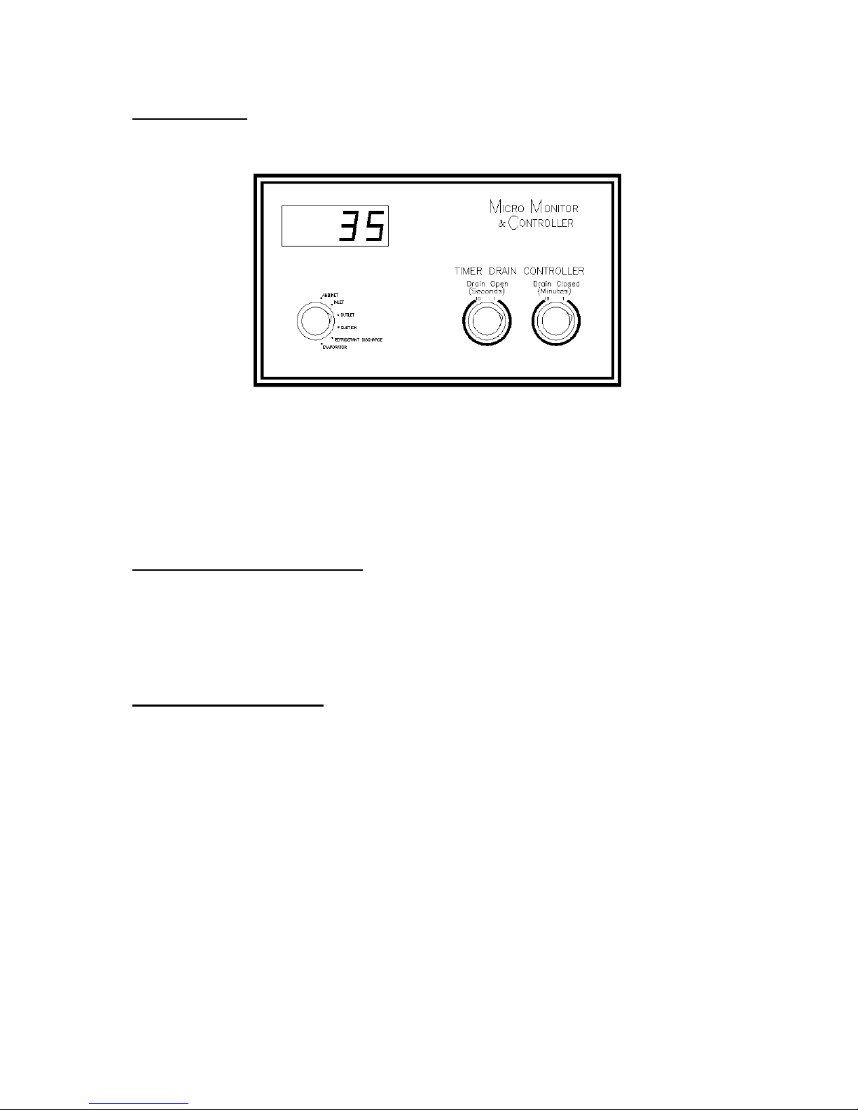
Micro-Monitor: The Pioneer Micro-Monitor is standard in models R75/ADR40 and larger
(optional in smaller sizes). The dryer operation and performance are shown at a glance by selecting the
desired reading.
Maintenance
To maximize system performance and reliability, the following maintenance procedure is required:
Air and water cooled condensers must be inspected and cleaned periodically. Inspect and replace
prefilter and after-filter elements periodically (recommended monthly). To avoid downtime, always
keep spare elements in stock.
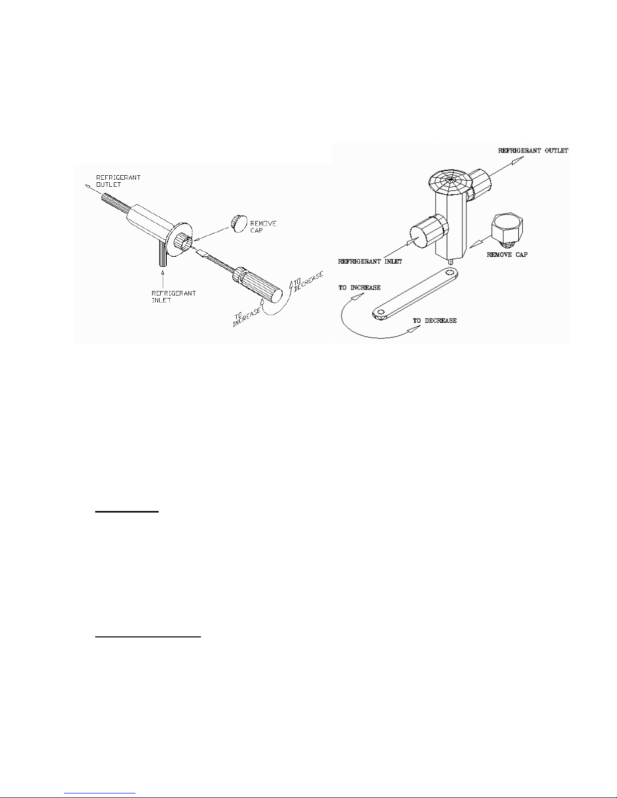
Automatic Drain Maintenance: The float type automatic drain is standard in models R10 and
R15. Clean drain periodically to ensure proper functioning. Remove air pressure before loosening the
separator bowl. In models R20 and larger, the three step automatic drain is standard. It includes an
isolation valve, a cleanable strainer, and a timer operated solenoid valve. Close the isolation valve before
removing and cleaning the strainer. Models R800/ADR400 and larger have an additional manual drain
on the air-air heat exchanger.
10-year Limited Warranty
A 10-year prorated heat exchanger warranty (through R5000/ADR2500) and a 10-year prorated
compressor warranty apply on standard Pioneer products. Pioneer standard dryers are warranted to be
free from defects in material and workmanship for a period of one year from the date of shipment (15
months for distributor stock units), provided the equipment is used according to the company’s
recommended usage. Liability is limited to the repair, refund, or replacement in kind at the company’s
sole option. In no event will Pioneer be liable or responsible for incidental and consequential damages,
even if the possibility of such has been made known to the company. The usual maintenance and
replacement-type products are not covered by this warranty. To protect this warranty, use genuine
Pioneer accessories and spare parts. One year mechanical parts only warranty applies to equipment
outside the U.S.A., Mexico, and Canada. Extended warranties are available. Contact your distributor for
details.
Please notify your distributor or the factory before working on equipment. Unauthorized work may
not be covered and may void the warranty. Please contact the factory to obtain a return merchandise
authorization number (RMA#) before returning equipment.
Caution: A refrigerant compressor operating under sustained overload conditions caused by excessive
airflow, high inlet air temperature, and/or ambient temperature will continue to work at a higher
8

9
discharge pressure until either the compressor motor fails or the compressor cycles on high pressure cut-
out control. If the dryer cycles for any reason, turn it off and contact factory; allowing it to cycle on high
pressure will burn up the compressor motor. Because of higher pressure and electrical voltage, only
qualified service personnel should work on the equipment. For critical applications, the factory
recommends that the customer install a back-up system.
WARNING:
Remove air pressure from the device under pressure before working on it.

10
TROUBLESHOOTING
PROBLEM REMEDY
1. System bypass open. Close bypass valve and open inlet/outlet valves
2. Excessive air flow. Check rated output capacity of air compressor; a larger system
may be needed.
3. High inlet air temperature. A larger system or after-cooler may be needed (consult factory)
4. Dirty heat exchanger. Disconnect dryer inlet/outlet and flush with steam cleaner and
copper solvent.
5. Drain malfunction. Clean or replace.
6. Not draining all moisture. Adjust on/off times to drain – longer and/or more frequently.
7. Refrigerant compressor cycling
due to high refrigerant pressure or
overload
a. Overloaded unit.
b. Dirty atmosphere.
c. High ambient temperature.
d. Condenser fan motor failure.
e. Incorrect high-pressure
shutdown setting.
f. Bad compressor.
Reduce load or install larger system.
Clean condenser and install filter. Relocate unit or convert to
water-cooled unit.
Provide suitable ventilation or relocate unit. Consult factory.
Repair or replace.
Correct to: R-134a: 235 PSIG/16.2 BarG
R-22: 350 PSIG/2724.1 BarG
Replace compressor and liquid and suction line filters.
8. Refrigerant compressor cycling on
low pressure
a. Refrigerant low.
b. Incorrect low pressure control
setting.
c. Low-pressure control
malfunction.
Inspect for leaks, repair, evacuate and recharge. Consult factory.
Correct to:
R-134a: cut out 20 PSIG/1.38 BarG, cut in 30 PSIG/2.07 BarG
R-22: cut out 40 PSIG/2.16 BarG, cut in 60 PSIG/4.14 BarG
Units supplied with pump down:
R-22: cut out 25 PSIG/1.73 BarG, cut in 35 PSIG/2.42 BarG
Replace.
9. Refrigerant suction temperature
too low/freeze up.
a. Check fan cycle switch (if
supplied).
b. Ambient temperature too low.
Correct settings:
#1 Fan
R-134a: cut out 75 PSIG/5.2 BarG, cut in 125 PSIG/8.6 BarG
R-22 : cut out 150 PSIG/10.4 BarG, cut in 230 PSIG/15.9 BarG
#2 Fan
R-134a: cut out 110 PSIG/7.6 BarG, cut in 160 PSIG/11.4 BarG
R-22 : cut out 200 PSIG/13.8 BarG, cut in 275 PSIG/19 BarG
Relocate unit to a heated room/install low ambient package.
Consult factory.

Thank You!
Thank you for choosing Pioneer. We recognize that you had a choice. The fact that you choose Pioneer
further inspires us to produce quality products of excellent value, performance, and reliability. A
passionate dedication to excellence and innovation has always been the key to our success, along with
our distributors and dealers who are the very best in our industry. Together, we are committed to
providing you with superior quality products and services at affordable prices.
SamBasseen
PresidentandCEO
Get an extra month warranty – FREE!
The information requested below helps us to determine how well we have met your expectations, and
gives us a direction for further improvements. Please complete the form and return a copy to us within
90 days of receiving the equipment. In appreciation of your efforts, we will extend the twelve month
portion of the Pioneer warranty by one month, to thirteen months from the date of shipment.
Service rates (net)
Labor: $80/hour or $500/day
Service truck or van: 50¢/mile
Travel, food, and lodging costs are the responsibility of the customer and are invoiced on a cost basis.
Name: ___________________ Title: ______________________
Company Name: _______________________________________
Address: _____________________________________________
City/St./Zip: __________________________________________
Complete and return a copy to: Phone: __________________ Model #: ____________________
Pioneer Air Systems, Inc. Serial #: _________________ Start up date: _________________
210 Flatfork Road Application: __________________________________________
Wartburg, TN 37887-9428 _____________________________________________________
_____________________________________________________
_____________________________________________________
_____________________________________________________
_____________________________________________________
Your Opinion Counts!
Excellent Good Fair Poor
Performance
Appearance
Price
Service
Features I would like to see in future models: ______________________________________________
___________________________________________________________________________________
___________________________________________________________________________________
11
This manual suits for next models
1
Table of contents