Pioneer Athletics VSX-5900S User manual
Operating
Instructions
GD
PIONEER
weaves
oreo
aeeeves
VSX-5IOOS
:
=|
FS
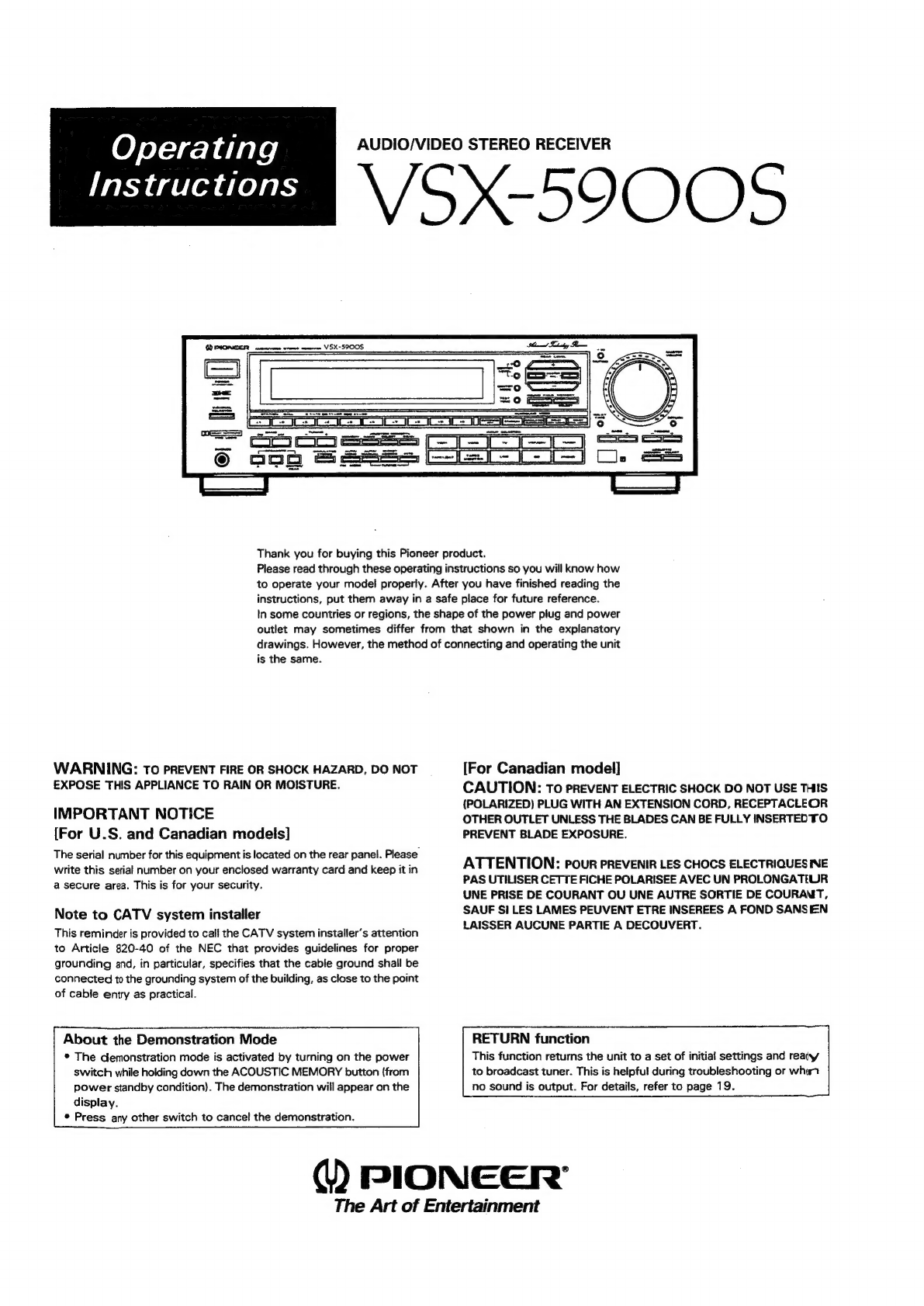
AUDIO/VIDEO
STEREO
RECEIVER
VSX-5900S
Thank
you
for
buying
this
Pioneer
product.
Please
read
through
these
operating
instructions
so
you
will
know
how
to
operate
your
model
properly.
After
you
have
finished
reading
the
instructions,
put
them
away
in
a
safe
place
for
future
reference.
In
some
countries
or
regions,
the
shape
of
the
power
plug
and
power
outlet
may
sometimes
differ
from
that
shown
in
the
explanatory
drawings.
However,
the
method
of
connecting
and
operating
the
unit
is
the
same.
WARNING:
To
PREVENT
FIRE
OR
SHOCK
HAZARD,
DO
NOT
EXPOSE
THIS
APPLIANCE
TO
RAIN
OR
MOISTURE.
IMPORTANT
NOTICE
[For
U.S.
and
Canadian
models]
The
serial
number
for
this
equipment
is
located
on
the
rear
panel.
Please
write
this
serial
number
on
your
enclosed
warranty
card
and
keep
it
in
a
secure
area.
This
is
for
your
security.
Note
to
CATV
system
installer
This
reminder
is
provided
to
call
the
CATV
system
installer’s
attention
to
Article
820-40
of
the
NEC
that
provides
guidelines
for
proper
grounding
and,
in
particular,
specifies
that
the
cable
ground
shall
be
connected
to
the
grounding
system
of
the
building,
as
close
to
the
point
of
cable
entry
as
practical.
About
the
Demonstration
Mode
*
The
demonstration
mode
is
activated
by
turning
on
the
power
switch
while
holding
down
the
ACOUSTIC
MEMORY
button
(from
power
standby
condition).
The
demonstration
will
appear
on
the
display.
©
Press
any
other
switch
to
cancel
the
demonstration.
[For
Canadian
model]
CAUTION:
To
PREVENT
ELECTRIC
SHOCK
DO
NOT
USE
THIS
(POLARIZED)
PLUG
WITH
AN
EXTENSION
CORD,
RECEPTACLEOR
OTHER
OUTLET
UNLESS
THE
BLADES
CAN
BE
FULLY
INSERTED
TO
PREVENT
BLADE
EXPOSURE.
ATTENTION:
Pour
PREVENIR
LES
CHOCS
ELECTRIQUES
NE
PAS
UTILISER
CETTE
FICHE
POLARISEE
AVEC
UN
PROLONGATIUR
UNE
PRISE
DE
COURANT
OU
UNE
AUTRE
SORTIE
DE
COURANT,
SAUF
SI
LES
LAMES
PEUVENT
ETRE
INSEREES
A
FOND
SANSEN
LAISSER
AUCUNE
PARTIE
A
DECOUVERT.
RETURN
function
This
function
returns
the
unit
to
a
set
of
initial
settings
and
reaiy
to
broadcast
tuner.
This
is
helpful
during
troubleshooting
or
what
no
sound
is
output.
For
details,
refer
to
page
19.
@)
PIONEER’
The
Art
of
Entertainment

IMPORTANT
The
lightning
flash
with
arrowhead,
within
an
equilateral
triangle,
is
intended
to
alert
the
user
to
the
presence
of
uninsulated
‘‘dangerous
voltage’
within
the
product's
enclosure
that
may
be
of
sufficient
magnitude
to
constitute
a
risk
af
electric
shock
to
persons.
READ
INSTRUCTIONS
—
All
the
safety
and
operating
instructions
should
be
read
before
the
appliance
is
Operated,
RETAIN
INSTRUCTIONS
—
The
operating
instructions
should
be
retained
for
future
reference.
HEED
WARNING
—
All
warnings
on
the
appliance
and
in
the
operating
instructions
should
be
adhered
to.
FOLLOW
INSTRUCTIONS
—
All
operating
and
use
in-
structions
should
be
followed.
WATER
AND
MOISTURE
—
The
appliance
should
not
be
used
near
water
—
for
example,
near
a
bathtub,
washbowl,
kitchen
sink,
laundry
tub,
in
a
wet
base-
ment,
or
near
a
swimming
pool,
etc.
LOCATION
—
The
appliance
should
be
installed
in
a
stable
location.
WALL
OR
CEILING
MOUNTING
—
The
appliance
should
not
be
mounted
to
a
wall
or
ceiling.
VENTILATION
—
The
appliance
should
be
situated
so
that
its
location
or
position
does
not
interfere
with
its
proper
ventilation.
For
example,
the
appliance
should
not
be
situated
on
a
bed,
sofa,
rug,
or
similar
surtace
that
may
block
the
ventilation
openings;
or,
placed
in
a
built-in
installation,
such
as
a
bookcase
or
cabinet
that
may
impede
the
flow
of
air
through
the
ventilation
openings.
HEAT
—
The
appliance
should
be
situated
away
from
heat
sources
such
as
radiators,
heat
registers,
Stoves,
or
other
appliances
{including
amplifiers)
that
produce
heat.
POWER
SOURCES
—
The
appliance
should
be
con-
nected
to
a
power
supply
only
of
the
type
de-
scribed
in
the
operating
instructions
or
as
marked
on
the
appliance.
POWER-CORD
PROTECTION
—
Power-supply
cords
should
be
routed
so
that
they
are
not
likely
to
be
walked
on
or
pinched
by
items
placed
upon
or
against
them.
Pay
particular
attention
to
cords
at
Plugs,
convenience
receptacies,
and
the
point
where
they
exit
from
the
appliance.
POLARIZATION
—
!f
your
purchased
product
is
pro-
vided
with
a
polarized
power
plug,
please
read
the
following
instructions.
This
product
is
eauipped
witha
polarized
alternating
current
tine
plug
(a
plug
having
one
biade
wider
than
the
other).
This
plug
will
fit
into
the
power
outlet
only
one
way.
This
is
a
safety
feature.
If
you
are
unable
to
insert
the
plug
fully
into
the
outlet,
try
reversing
the
plug.
If
the
Plug
shouid
still
fail
to
fit,
contact
your
electrician
to
replace
your
obsolete
outlet.
Do
not
defeat
the
Safety
purpose
of
the
polarized
plug.
CLEANING
—
The
appliance
should
be
cleaned
only
with
a
polishing
cloth
or
a
soft
dry
cloth.
Never
clean
with
furniture
wax,
benzine,
insecticides
or
other
volatile
liquids
since
they
may
corrode
the
Cabinet.
2
<ARB1327>
CAUTION
RISK
OF
ELECTRIC
SHOCK
00
NOT
OPEN
CAUTION:
TO
PREVENT
THE
RISK
OF
ELECTRIC
SHOCK,
DO
NOT
REMOVE
COVER
(OR
BACK).
NO
USER-
SERVICEABLE
PARTS
INSIDE.
REFER
SERVICING
TO
QUALIFIED
SERVICE
PERSONNEL.
POWER
LINES
—
An
outdoor
antenna
should
be
located
away
from
power
lines.
NONUSE
PERIODS
—
The
power
cord
of
the
appliance
should
be
unplugged
from
the
outlet
when
left
un-
used
for
a
long
period
of
time.
OBJECT
AND
LIQUID
ENTRY
—
Care
should
be
taken
so
that
objects
do
not
fall
and
liquids
are
not
spilled
into
the
enclosure
through
openings.
DAMAGE
REQUIRING
SERVICE
—
The
appliance
should
be
serviced
by
a
Pioneer
authorized
service
center
or
qualified
service
personnel
when:
The
power-supply
cord
or
the
plug
has
been
dam-
aged.
Objects
have
fallen,
or
tiquid
has
been
spilled
into
the
appliance.
The
appliance
has
been
exposed
to
rain.
The
appliance
does
not
appear
to
operate
normally
or
exhibits
a
marked
change
in
performance.
The
appliance
has
been
dropped
or
the
enclosure
damaged.
SERVICING
—
The
user
should
not
attempt
to
service
the
appliance
beyond
that
described
in
the
opera-
ting
instructions.
For
all
other
servicing,
contact
the
nearest
Pioneer
authorized
service
center.
ELECTRIC
SERVICE
EQUIPMENT
FiG.A
SAFETY
INSTRUCTIONS
The
exclamation
point
within
an
equilateral
triangle
is
intended
to
alert
the
user
to
the
presence
of
important
operating
and
maintenance
(servicing)
instructions
in
the
literature
accampanying
the
appliance.
OUTDOOR
ANTENNA
GROUNDING
—
If
an
outside
an-
tenna
is
connected
to
the
antenna
terminal,
be
sure
the
antenna
system
is
grounded
so
as
to
provide
some
protection
against
voltage
surges
and
built
up
static
charges.
In
the
U.S.A.
section
810
of
the
National
Electrical
Code,
ANSI/NFPA
No.
70-1984,
provides
informa-
tion
with
respect
to
proper
grounding
of
the
mast
and
supporting
structure,
grounding
of
the
lead-in
wire
to
an
antenna
discharge
unit,
size
of
grounding
conductors,
location
of
antenna
discharge
unit,
connection
to
grounding
electrodes,
and
require-
ments
for
the
grounding
electrode.
See
Fig.
A.
CART
—
An
appliance
and
cart
combination
should
be
moved
with
care.
Quick
stops,
excessive
force,
and
uneven
surfaces
may
cause
the
appliance
and
cart
combination
to
overturn.
=a
NEC
—
NATIONAL
ELECTRIC
CODE
ANTENNA
LEAD
IN
WIRE
ANTENNA
DISCHARGE
UNIT
(NEC
SECTION
810
=
20)
GROUNDING
CONDUCTORS
{NEC
SECTION
810
-
21)
GROUND
CLAMPS
POWER
SERVICE
GROUNDING
ELECTRODE
SYSTEM
{NEC
ART
250,
PART
H}

CONTENTS
BEFORE
OPERATING,
ADJUST
THE
POSITION
OF
THESE
SWITCHES.
.............c:eccecseseeseeeneeeeeterees
4
FEATURES
i
csacescveccsdehate
cobs
tipawendad
ese
¥ideh
wed
Shades
gai
dewedadi
Seed
e
cele
tales
bdedaeaceael
Setenteceinciea
senate
cys
4
ACCESSORY
ITEMS)
wcscscacids
oe
ceddcceccucacedscdesvcaeucsesiaens
feed
ox
condceysccataees
wedded
mands
sans
tsed ence
ome
teases
5
BEOCK
DIAGRAM
es
ise
csed
wade
ool
dees
cbse
ste
uiconsehenagentaeenoaeteil
an
ucletey
cn
omamecedaan
dey
eats
Veigawee
ge
uraseasaneen
eds
5
SURROUND
EFFECT
SADIE
sskles
cesy
sees
ooh
is
eee
end
Sa
cd
ceva
veh
leis
Se
Se
ceeietasbhe
a
stacpaes
RAG
ETA
oe
akan
sae
siden
etesaantetensge
6
SIMULATED
SURROUND
..........cccccccssscccescecerercccesersccececeessneersreeeesseesseseesecsentatenserseesnaee
nena
6
DOLBY
SCH
LOGIC.
itevcsdectencevostecesiceveceucdewslaceos
thaciiates'seoekas
ve
ecderateaed
sete
eestesesN
a
eats
te
ceeendense
6
DOLBY
PRO
LOGIC
SURROUND
...........:cccecscceceeeceeeec
rene
et
enenees
seca
eeeeecssneneeseseeeneneeteeesneneeeeenees
6
SIMULATED
STEREO
........0.0:0ccscececcceaccutcesesccsenenaceeseescesstesersrcacsancecnseeseeereesearesencnteaseceereree
7
CONNECTIONS)
2.45.c2.2se
ote’
clciect
wage
cag
ta
code
ottavoaesiaet
cateacsuairadgig
iaey
se
Se
datebe
a
nceanaan
omen
temabaades
7
Basic
audio
SySteEM
CONNECTIONS...........c.eceeeeseeenseteseeeeeeeaeeeeeeraeceereeteeneeeeeeerteaeeeonseeneaesaneeetas
8
Basic
video
SYSt@M
CONMNECTIONS............ccseeeeeeeeeeceeeeeseeeeneoeeeeeneeeea
eee
sceseeeceeneeceeeesentenseeeene
9
Speaker
COMMECtIONS.............ceeeeeeeeeeeeeeeeetereenesneseneseeseeeseeseessessesersaneanananereneetereenenrseenertenes
10
Applications
.........seccecceeceeeeecereeneeseeeeeneeeeeeeneneeeeereeeeeeee
een
eesaeenesensaereeseseeet
eee
ees
enseenes
11
—
14
PEAR
PAINE:
FACILITIES
|
a.
cdsvscsacckass4eaninadntiia
tees
imstieeisessesedetasoateauseaduessytabinccebuiaasleast
15
PBODIT
ARV
EL
CAG
UIE
2504s
caress
doex
chav
ae
vated
eal
eccuelaateniuentnet
bacatine
ace
ecient
18
STEPWISE
OPERATION
PROCEDURES
BROADCAST
RECEPTION
Direct
ACCESS
TUNING
...........cceseeeecceecenseeenseeseeesecneceseeecesaeneneeenerecseseneeeeseressauseaneeaneneneneanens
22
Auto
or
manual
tuning
...........:cesccecececeeeecceeeeeeeeaeecneneenssaeseansecerensesereeecaeessaeeeeensenssnsenenenaes
23
PRESET
TUNING
Frequency
presetting
...........ccceeccsecseceeeseeessecenensaeecesceeeneeesanaereeaceeseueeeseceueseeceeeaerenaeeeaeeees
23
Listening
to
broadcasts
USING
PreS€t
TUNING
....-...eceeerecnscereeeeesenes
nes
eeseeeasesensereeeeeseetentan
eg
eaes
24
How
to
use
the
CUSTOM
MEMOLY
........cccceececeeeretereeseeceeeecaseeenereteeserenseseeeseeceneenenereceeeuewenes
24
Rte
i
ee
ce
nn
tena
26
SELECTING
DIFFERENT
PROGRAM
SOURCES.
..........:::csscscuscescecetcessetesseeeeeseeessseeereseseneenonens
27
HOW
TO
USE
THE
ACOUSTIC
MEMORY
..........c.::ccecsecneccceneensessenseseneceneeeeeeenesseesessoeeeternenees
27
HOW
TO
USE
THE
SOUND
FIELD
MEMORY
...........:.ccecceeeeeeseseeeeeseeseseeeeeeteeseesseeseeoneeeeecneeetes
28
RECEIVING
FM
SIMULCAST
TV
PROGRAMG
.............:sccseeececeeeenreceeneseeeneesneeeeenenessenecesaaeeaeeees
28
TO
WATCH
VIDEO
PROGRAMS.
..........0cccsceccncceeneceeneeeeteeeeeese
eee
eeeegeeeeeeneseseesneeeneeeaesneaeeenenegns
29
RECORDING
WITH
A
CASSETTE
DECK
ReCOrdiNg
..........ccceeceeeeceeeenece
eee
eeeeeeeneeeeeeeet
eee
een
esecenee
nessa
eee
eeee
eee
eese
eee
esee
nena
nena
esee
een
eeseneees
29
COpying
taDeS
.........cccecceseceneeceeeeeneeeeeeneeeeeeeeeeneeeeeeeeeeeeeeeneeeeeneeeee
nese
a
este
eEeCae
EERE
ee
EEe
a
EES
ESSE
EE
29
Hier’
VCR
RECORDING
iooecececinceietaceaveeces
iesetileds
act
sacs
sSagducde
saveveoscawsniatsctsaeeneant
seas
etek
see
deg
30
VIDEO:
TAPE
RECORDING
ccccscasstccccusscevsececstessesesstectuasaetececestoesetassesebasedeeauedeseaseadsnencaehaeateys
30
USING
THE
VIDEO
SIGNAL
SELECTOR..............cscecceseeesecceeseeeeneeessraesneeeeeeesseecsenseeseeeseeeceeres
31
DOLBY
SURROUND
LEVEL
ADJUSTMENT
PROCEDURE
yo
vsstssssetsessessoeneneess
Resid
ond:
31
REMOTE:
CONTROL
OPERATION)
x
cuaciaskaasn
stile
tudatts
ca
adlsavecnch
bine
samennivebedsinaatiod
32
Operation
......2...--ccececeseesevscecsseececeseeseseeasesesaasenaseesaneeneeseeeeeeees
schagdaecancetbapnbsvantedeosece
cesses
33
Programming
..........cc:esssesccnseeseeeeesseseeeceseeseccoseececessaneeecesssseseueoeseusanssccsenseeseueuesesenaeseesens
38
TROWBLESHOOTING
25.2565
coves
-cesatsesnesersthveeeccccwensucscapeastcy
sien
dentvesdinssdvewpoaa
dpsedascaedavenve
sede
sens
41
SPECIFICATIONS
iccccivcestecsncceteccsetebosvovs
awe dee
Vets
te
onccvsuwacubanestadesciudecessngdevele
eadaaaadugnet
ens
areca
nese
43
3
<
ARB13277
>

BEFORE
OPERATING,
ADJUST
THE
POSITION
OF
THESE
SWITCHES
TWO
VOLTAGE
SELECTOR
SWITCHES
Only
multi-voltage
models
are
provided
with
these
switches.
U.S.,
Canadian,
European,
U.K.
and
Australian
models
are
not
provided
with
these
switches.
Mains
voitages
in
Saudi
Arabia
are
127
V
and
220
V
only.
Never
use
this
model
with
110
V
setting
in
Saudi
Arabia.
The
line
voltage
selector
switches
are
on
the
rear
panel.
Before
your
model
is
shipped
from
the
factory,
these
switches
are
set
to
the
power
requirements
of
the
destination.
Check
that
they
are
set
properly
before
plugging
the
power
cord
into
the
household
wall
socket.
If
the
voltage
is
not
properly
set
or
if
you
move
to
an
area
where
the
voltage
requirements
differ,
adjust
the
selector
switches
as
follows.
1.
Use
a
medium-size
screwdriver.
2.
First,
insert
a
screwdriver
in
the
groove
of
the
voltage
selector
at
the
right,
and
adjust
so
that
the
tip
of
the
groove
points
to
the
voltage
value
of
your
area.
3.
Next,
insert
a
screwdriver
in
the
groove
of
the
voltage
selector
at
the
left
and
adjust
until
the
voltage
is
the
same
as
at
the
right.
TWO
VOLTAGE
SELECTORS
i
4
220V
aan
1WOV
120V~127V
Medium-size
screwdriver
NOTE:
Both
switches
must
be
in
the
same
switch
setting;
otherwise,
unit
can
be
damaged.
2)
c
°
i
oO
w
4
w
7)
w
ru)
he
=)
°
>
FEATURES
The
VSX-5900S
audio-video
component
combines
the
functions
of
receiver,
wireless
remote
control,
audio-video
selector
and
surround
processor.
This
unit
will
play
a
central
role
in
your
enjoyment
of
audio-
visual
media.
©
BUILT-IN
DIGITAL
DELAY,
DOLBY
SURROUND
CIRCUIT
Enjoy
the
presence
and
the
expansive
effect
of
surround
piayback.
Four
different
surround
effect
(STADIUM,
SIMULATED
SURROUND,
DOLBY
3CH
LOGIC,
DOLBY
PRO
LOGIC)
and
7-step
delay
times
(STADIUM,
SIMULATED
SURROUND),
4-step
delay
times
(DOLBY
PRO
LOGIC)
are
available.
¢
LARGE,
MOTOR
DRIVEN
VOLUME
KNOB
The
large
volume
knob
contributes
to
operational
convenience
and
positive
response.
You
can
even
operate
it
via
remote
control.
When
you
change
the
volume
setting
using
the
remote
control
unit,
the
knob
turns
by
itself,
making
it
easy
to
keep
track
of
the
current
setting.
*
VIDEO
SIGNAL
SELECTOR
(Simulcast
function)
Allows
free
combination
of
various
audio-visual
sources
during
playback
and
over-dubbing,
enabling
you
to
produce
your
own
original
video
Product.
¢
TWO-WAY
VCR
COPYING
AND
MONITORING
VCR
1
—
VCR
2:
Copying
of
video
cassette
tapes
can
be
performed
in
either
direction.
VDP/CDV
—
VCR
1,
VCR
2:
Allows
simultaneous
production
of
two
Copies
from
video
disc
or
compact
disc
with
video.
4
<ARB1327>
CAUTION:
TWO
VOLTAGE
SELECTORS
a
mY
lace
aaat
-127V
CHANNEL
STEP/FM
DE-EMPHASIS
SWITCH
(Not
available
on
U.S.
and
Canadian
models)
The
unit
has
been
factory
preset
to
the
channel
allocation
and
de-
emphasis
value
for
the
area
in
which
it
is
to
be
sold.
If
these
values
are
set
incorrectly,
the
frequency
display
may
stop
at
the
wrong
frequency,
or
sound
may
be
distorted,
resulting
in
an
inability
to
reproduce
reception
signals
at
their
proper
sound
quality.
For
this
reason,
be
sure
to
confirm
that
the
values
are
set
correctly
before
first
using
the
unit.
[100
kHz/10 kHz/75
us]
position:
Set
to
this
position
for
areas
with
an
FM
reception
step
of
100
kHz,
AM
10
kHz,
and
de-emphasis
75
ys.
[50
kHz/9
kHz/50
us]
position:
Set
to
this
position,
for
areas
with
an
FM
reception
step
of
50
kHz,
AM
9
kHz,
and
de-emphasis
50
us.
NOTE:
When
unsure
about
the
channel
allocation
and
de-emphasis
values
for
your
area,
consult
your
dealer
for
correct
information.
CHANNEL
STEP
/FM
DE-EMPHASIS
FM
AM
v Y
5OkHz-9kHz
/SOxS
‘—*
rere’
100kH2-1OkHz
/75uS
¢
SOUND
FIELD
MEMORY
FUNCTION
Surround
mode,
Balance,
Delay
time,
and
Acoustic
memory
are
among
the
5
presets
possibie
with
this
function.
@
ACOUSTIC
MEMORY
FUNCTION
Five
types
(A—E)
of
tone
control
settings
can
be
preset.
The
settings
for
loudness
and
flat
tone
response
functions
can
also
be
selected
quickly.
¢
CUSTOM
MEMORY
FUNCTION
Stations
can
be
preset
according
to
the
genre
of
the
material
broadcast,
and
Memory
Scan
of
a
particular
genre
can
be
carried
out.
¢
MULTI-ROOM
REMOTE
JACK
The
optional
MR-100
Multi-room
remote
control
unit
can
be
connected
to
the
Multi-room
remote
IN
jack.
*
60/30-MINUTE
SLEEP
TIMER
FUNCTION
¢
AV
PROGRAMMABLE
REMOTE
CONTROL
WNIT
WITH
SELF-ILLUMINATED
BUTTONS
With
the
attached
remote
control
unit
you
can
operate
any
Pioneer
audio
or
video
component
bearing
the
fal
mark.
Using
additional
learning
functions
a
whole
AV
surround
system
including
a
TV
and
VCR
from
other
manufacturers
can
be
controlled.
(Some
manufacturers’
7emote
control
systems,
however,
are
not
suitable
for
programming.)
Pre-programmed
with
Codes
to
control
TVs
and
VCRs
from
other
12
major
manufacturers.

ACCESSORY
ITEMS
FM
T-type
Antenna
AM
Loop
Antenna
Audio/Video
programmable
remote
control
unit
BLOCK
DIAGRAM
FRONT
TAPE
2
poe
ones
REC
PLAY
©)
©
O
FMO
AMO
TUNER
|
9
MASTER
JS
O
PHONO
OL
EQ fo
OO
O-O
co
@——o
—
=a
————]
. P
S/S
ne
>}
eacance
}-[S)
Fy
Line
Q——-0
Prrr
eee
7
TAPE
1Q———o
jas
FS
A
DIGITAL
Y
oS
simaree
TV
Sis
fem
gan
p
|
ros:com
[]at*t8ae-—J
Bac
vcr!
O
Alkaline
dry
cell
battery
(size
“AA”
(LR6/AM-3))
SP-A
ON/OFF
O”O——————O
SP-A
O~O——__—©
SP-B
SP-B
ON/OFF
J
Headphone
3
fF
REAR-L
DELAY
Leven
Hh
LOO
Seer
‘
‘
poe
REAR
SP
VCR
2
:
man
mean
aan
1
4
ON/OFF
VDP/CDV
H
QO
9
'
CRs
:
PRE
POWER
:
TAPE
1
/DAT
J
:
OUT
IN
{
t
!
recO
ome
wage
REAR
H
vcR1touTO
TO
'
veR2
0uTO——_o-0—
a,
a
eee
=.)
s
eh
N
=
CENTER
=
O—O
BEAKER
SON
SOF
sP
ON/OFF
O
PRE
POWER
OUT
IN
CENTER
MONITOR
ouT
5
<ARB1327
>
SURROUND
EFFECT
This
unit
has
a
built-in
surround
processor
for
adding
presence
and
an
expansive
effect
to
the
sound.
¢
STADIUM:
Effective
for
a
stereo
but
not
a
monaural
source.
The
“STADIUM”
effect
creates
efficient,
reverberated
sounds
to
obtain
an
expansive
sound
field.
For
music
sources
like
a
rock
concert,
you
can
feel
if
you
were
at
the
live
concert
seated
very
close
to
the
stage.
For
sports
programs
such
as
a
baseball
game,
you
can
enjoy
a
powerful
sound,
thus
obtaining
a
stadium-like
effect.
¢
SIMULATED
SURROUND:
The
*‘SIMULATED”
creates
effects
of
reverberated
and
reflected
sound
from
the
walls
and
ceiling,
similar
to
a
concert
hall.
These
sound
effects
added
to
the
actual
sound
from
the
source
make
you
feel
as
if
in
a
more’
expanded
space.
The
different
ranges
of
the
expanded
space
can
be
set
by
the
DELAY
TIME
button.
For
example,
set
the
Delay
Time
to
15
ms
or
20
ms
for
a
live-house
concert.
For
chamber
music,
set
to
20
ms.
For
orchestral
music,
set
to
35
ms.
The
“SIMULATED”
also
gives
the
effects
on
monaural
sources
by
outputting
the
reverberated
sound
from
rear
speakers
while
keeping
the
output
sound
from
front
speakers
as
it
is.
Turn
on
the
““SIMULATED”
for
a
monaural
source
to
gain
the
effective
surround
playback.
When
using
a
monaural
source,
it
is
more
effective
if
used
with
SIMULATED
STEREO.
¢
DOLBY
3CH
LOGIC:
Combining
the
rear
speaker
signal
with
that
of
the
front
speakers
results
in
your
being
able
to
enjoy
a
regenerated
sound
field
which
has
comparatively
more
presence
and
a
more
expansive
feeling
from
the
front
3
channels
(front
L,
front
R,
and
center
speakers)
than
that
of
ordinary
stereo
regeneration.
*
DOLBY
PRO
LOGIC
SURROUND:
Choose
this
setting
for
movies
and
music
(especially
Video
Discs
and
video
tapes
bearing
the
Diq
mark)
playback.
DOLBY
PRO
LOGIC
SURROUND
continuously
detects
the
size
and
direction
of
the
dominant
signal
and
cancels
undesirable
crosstalk,
thereby
providing
signal
emphasis.
It
makes
you
clearly
perceive
the
directions
where
music
comes
from.
Real
flow
of
sound
also
can
be
re-created
naturally
using
this
feature.
You
can
feel
as
if
being
in
the
outstanding
and
expansive
sound
field.
[For
DOLBY
PRO
LOGIC
SURROUND
and
DOLBY
3CH
LOGIC)
You
can
choose
from
the
following
settings:
Center
Mode
Choices:
(When
using
a
center
speaker:)
°
NORMAL
—
Low
range
frequencies,
which
have
little
effect
on
directionality
and
positioning,
are
routed
to
the
feft
and
right
front
speakers.
So
you
can
use
a
relatively
small
size
speaker
as
the
center
speaker.
«
WIDE
—
If
you
use
a
large
size
center
speaker,
choose
this
setting.
The
full
frequency
range
of
the
Dolby
Surround
center
channel,
from
low
to
high,
is
routed
to
the
center
speaker.
(When
not
using
a
center
speaker:
DOLBY
PRO
LOGIC
SURROUND)
©
PHANTOM
—
The
signal
which
would
have
been
sent
to
the
center
speaker
is
divided
equally
between
the
left
and
right
front
speakers.
When
using
DOLBY
PRO
LOGIC
SURROUND,
a
delay
time
setting
of
20
ms
is
commonly
used.
Use
a
different
setting
if
you
prefer.
Even
if
they
do
not
bear
the
oO
mark,
some
video
recordings
may
be
Dolby
Surround
encoded.
6
<ARB1327>
DOLBY
3CH
LOGIC
can
be
used
with
stereo
sources
not
encoded
with
DOLBY
SURROUND.
Choose
the
SIMULATED
SURROUND
mode
if
the
source
sound
signal
is
mono.
Little
or
no
sound
will
be
heard
from
the
surround
speakers
if
the
STADIUM
or
DOLBY
PRO
LOGIC
SURROUND
mode
is
selected.
With
DOLBY
PRO
LOGIC
SURROUND,
monaural
source
sound
will
be
heard
only
from
the
center
channel
at
settings
other
than
the
PHANTOM
position.
Manufactured
under
license
from
Dolby
Laboratories
Licensing
Corporation.
Additionally
licensed
under
one
or
more
of
the
following
patents:
U.S.
numbers
3,632,886,
3,746,792
and
3,959,590;
CANADA
numbers
1,004,603
and
1,037,877.
“‘Dolby’’
and
the
double-D
symbol
are
trademarks
of
Dolby
Laboratories
Licensing
Corporation.
Manufacturé
sous
licence
de
Dolby
Laboratories
Licensing
Corporation.
En
outre,
sous
license
d’un
ou
plusiers
des
brevets
suivants:
numéros
américains
3,632,886,
3,746,792
et
3,959,590;
numéros
canadiens
1,004,603
et
1,037,877.
Le
terme
‘‘Dolby”’
et
le
symbole
Double-D
sont
des
marques
déposées
de
Dolby
Laboratories
Licensing
Corporation.
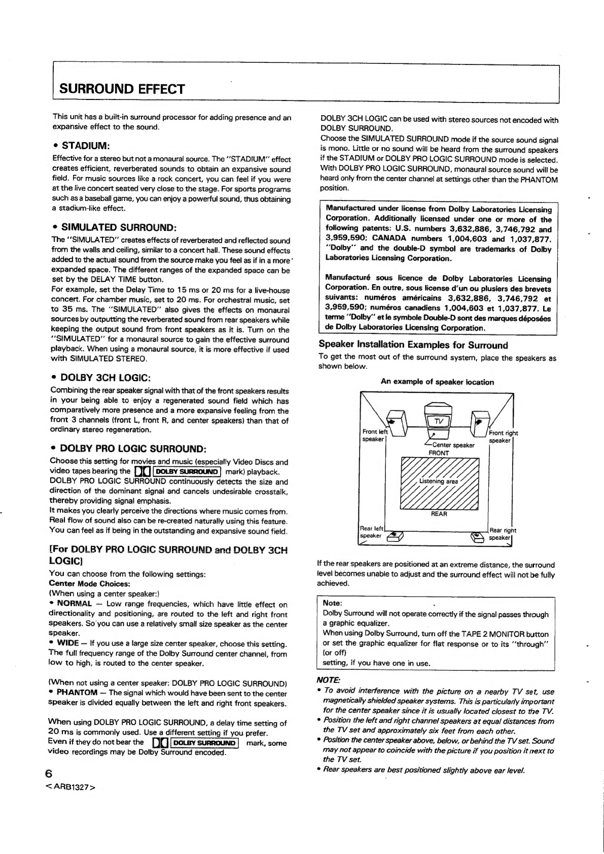
Speaker
Installation
Examples
for
Surround
To
get
the
most
out
of
the
surround
system,
place
the
speakers
as
shown
below.
An
example
of
speaker
location
ront
right
speaker
Center
speaker
"
FRONT
If
the
rear
speakers
are
positioned
at
an
extreme
distance,
the
surround
level
becomes
unable
to
adjust
and
the
surround
effect
will
not
be
fully
achieved.
Note:
.
Dolby
Surround
will
not
operate
correctly
if
the
signal
passes
through
a
graphic
equalizer.
When
using
Dolby
Surround,
turn
off
the
TAPE
2
MONITOR
button
or
set
the
graphic
equalizer
for
flat
response
or
to
its
“through”
{or
off)
setting,
if
you
have
one
in
use.
NOTE:
°
To avoid
interference
with
the
picture
on
a
nearby
TV
set,
use
magnetically
shielded
speaker
systems.
This
is
particularly
important
for the
center
speaker
since
it
is
usually
located
closest
to
the
TV.
*
Position
the
left
and
right
channel
speakers
at
equal
distances
from
the
TV
set
and
approximately
six
feet
from
each
other.
°
Position
the
center
speaker
above,
below,
or
behind
the
TV
set.
Sound
may
not
appear
to
coincide
with
the
picture
if
you
position
it
next
to
the
TV
set.
©
Rear
speakers
are
best
positioned
slightly
above
ear
level.

SIMULATED
STEREO
This
function
transforms
monaural
signals
into
simulated
stereo
sound.
Use
it
when
you
wish
to
experience
a
sense
of
stereo
presence
when
listening
to
AM
broadcasts,
or
VCR
and
other
monaural
signal
sources.
NOTE:
©
The
simulated
stereo
function
can
also
be
used
with
stereo
sound
sources,
but
it
will
result
in
an
effect
somewhat
different
from
the
normal
stereo
sound.
¢
With
a
monaural
source,
switch
the
SURROUND
MODE
to
the
SIMULATED
SURROUND
position.
In
any
other
position
(STADIUM,
DOLBY
SURROUND),
there
will
be
no
effect.
CONNECTIONS
Setting
Up
the
AM
Antenna
©
Insert
the
claw
on
the
bottom
of
the
antenna
into
the
hole
in
the
leg.
*
Place
the
antenna
on
a
tevel
surface
and
rotate
it
to
locate
the
orientation
that
yields
the
best
reception.
Use
the
attachment
hole
in
the
leg
to
screw
to
wall
or
other
location,
then
insert
the
claw
on
the
bottom
of
the
antenna
into
the
hole
in
the
leg
(fixing
the
antenna
in
the
direction
that
gives
the
best
reception).
Lead
wire
Precaution
regarding
installation
position
of
cassette
deck.
If
the
cassette
tape
deck
is
installed
in
the
@
positions
shown
in
the
drawing
below,
hum
may
occur
during
playback.
If
there
is
any
hum,
move
the
unit
away
to
a
position
where
the
hum
goes
away.
7
<ARB1327
>

CONNECTIONS
NOTE
FOR
FM
T-TYPE
ANTENNA:
BASIC
AUDIO
SYSTEM
CONNECTIONS
Stretch
the
antenna
out
to
its
full
length,
and
affix
it
to
a
wall,
etc.
8
NOTE
FOR
AM
LOOP
ANTENNA:
The
antenna
should
be
placed
at
a
distance
from
the
receiver,
and
should
not
be
allowed
to
touch
metallic
objects.
Avoid
placing
it
near
CD
players,
personal
computers,
television
sets,
and
other
devices
generating
radio
frequencies.
Power
cord
connection
Turntable
Accessory
AM
Loop
antenna
Accessory
FM
T-type
antenna
CD
player
CONNECTING
THE
POWER
CORD
(For
U.S.
and
Canadian
models)
Household
electrical
outlets
are
provided
with
specific
polarity,
a
live
side
and
a
neutral
(ground)
side.
This
unit
utilizes
such
polarity
in
order
to
improve
sound
quality.
As
shown
in
the
illustration,
be
sure
to
insert
the
power
plug
so
that
its
blades
match
the
width
of
slots
in
the
outlet.
Househoid
electrical
outlet.
Long
slot
is
neutral
(ground)
side.
Insert
the
wide
blade
into
the
ground
side
slot.
CD
player
<ARB1327>
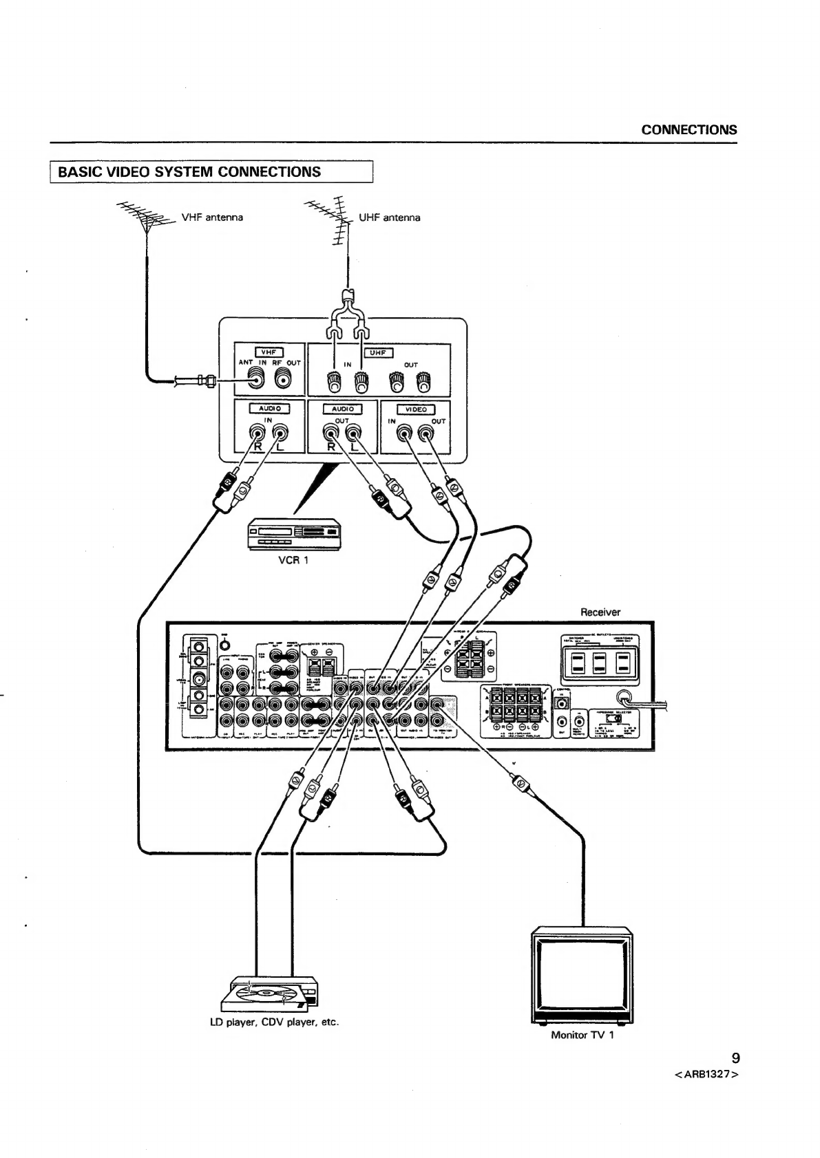
CONNECTIONS
BASIC
VIDEO
SYSTEM
CONNECTIONS
4
UHEF
antenna
VHF
antenna
Receiver
Monitor
TV
1
LD
player,
CDV
player,
etc.
<ARB1327>

CONNECTIONS
SPEAKER
CONNECTIONS
Left
Channel
Center
channel
Right
Channel
ZN,
Speaker
cord
connection
@
Push
the
knob.
@
Insert
the
cord.
@
Pull
the
knob.
Receiver
mm)
!{©@®
i!
©G
IMPEDANCE
SELECTOR
Set
to
match
the
impedance
of
the
speakers
being
used,
(See
page
17.)
Right
Channel
—_—
>»
[
A
ORB:
AORB:
40
TO
LESS
82
OR
THAN
8 2
MORE
A
+
B:
80
OR
MORE
Left
Channel
10
<ARB1327>

CONNECTIONS
APPLICATIONS
Note:
When
using
with
other
audio
or
video
components.
Audio
component
Cassette
deck
2
VIDEO
Dolby
Surround
will
not
operate
correctly
if
the
signal
passes
through
a
graphic
equalizer.
When
using
Dolby
Surround,
turn
off
the
TAPE
2
MONITOR
button
or
set
the
graphic
equalizer
for
flat
response
or
to
its
“through”
(or
off)
setting,
if
you
have
one
in
use.
When
using
a
graphic
equalizer
OUT
(Audio)
\
t
|
\
|
!
1
!
:
I
Graphic
\
equalizer
'
!
|
I
'
t
'
'
!
)
oLandR
To
Land
R
EC
jacks
PLAY
jacks
OUT
{Audio,
Video)
IN
OUT
(Audio,
(Audio)
Video)
OUT
TV
tuner
VCR
2
Monitor
TV
2
11
<ARB1327>

CONNECTIONS
ee
APPLICATIONS
When
used
with
another
amplifier
(power
amplifier,
pre-amplifier)
[FRONT]
(a)
When
using
the
pre-amplifier
of
the
receiver
and
using
a
separate
stereo
power
amplifier
to
increase
power.
(b)
When
using
the
power
amplifier
of
the
receiver
and
using
a
separate
stereo
preamplifier.
Remove
both
connector
bar
Keep
the
removed
bars
for
future
use.
12
<ARB1327>
When
using
PRE
AMP
OUT
jacks:
Use
these
jacks
when
using
a
separate
amplifier
as
the
power
source
instead
of
this
units,
and
listening
to
speakers
which
are
connected
to
the
separate
amplifier.
NOTE:
Sound
from
the
speaker
channels
(front,
center,
rear)
from
which
the
connector
bars
have
been
removed
in
order
to
make
@
connection
cannot
be
heard
if
the
speakers
are
connected
to
the
unit.
When
using
POWER
AMP
IN
jacks:
Use
these
jacks
when
this
unit
is
being
used
as
the
power
amplifier
for
the
surround channels
(front,
center,
rear).
With
separate
surround
processing
components,
each
corresponding
channel
(front,
center,
rear)
which
has
a
sound
output
should
be
connected
correspondingly.
NOTE:
When
the
connector
bars
are
removed
to
make
connections,
sound
from
all
channels
of
separate
components
connected
to
this
unit’s
input
terminals,
as
well
as
broadcasts
received
by
the
unit
become
unable
to
be
heard
via
speakers
connected
to
the
unit.
Receiver
Caution
for
use
of
AC
OUTLETS:
Components
which
have
electrical
power
consumption
greater
than
that
indicated
on
the
rear
panel
of
this
unit
cannot
be
connected.
Please
take
necessary
precaution.
Stereo
pre-amplifier

CONNECTIONS
[REAR
and
CENTER]
(a)
When
using
the
pre-amplifier
of
the
receiver
and
using
a
separate
power
(b)
Meee
amplifier
to
increase
power.
(b)
When
using
the
power
amplifier
of
the
receiver
and
using
a
separate
stereo
preamplifier.
Caution
for
use
of
AC
OUTLETS:
Components
which
have
electrical
power
consumption
greater
than
that
indicated
on
the
rear
panel
of
this
unit
cannot
be
connected.
Please
take
necessary
precaution.
Receiver
(a)
r--
Remove
both
connector
bars.
Keep
the
removed
bars
for
future
use.
os
Stereo
power
Stereo
pre-amplifier
amplifier
13
<ARB1327>
CONNECTIONS
OPTIONAL
MULTI-ROOM
CONTROL
ADAPTOR
CONNECTION
Multi-Room
Remote
control
unit
MR-100
(option)
ay
¢
For
details,
see
operating
instructions
for
multi-room
remote
control
unit
MR-100.
Be
careful
not
to
make
the
wrong
connections
for
CONTROL
IN/OUT
(black)
and
MULTI-ROOM
REMOTE
IN
(green).
ct
J
Speakers
A
Application
example
-
MULTI-AMPLIFIER
SYSTEM
Crossover
Network
High
range
You
can
operate
the
main
system
by
remote
contro!
from
a
different
room
in
which
are
installed
a
speaker
system
or
monitor
TV
set
if
you
aiso
install
a
Multi-Room
remote
control
unit
in
that
room.
Low
range
Power
Amplifier
=
POWER
AMP
OUT
IN
Receiver
{
PRE-AMP
POWER
AMP
=
Tweeter
Tweeter
Woofer
Speaker
system
14
.
<ARB1327>

REAR
PANEL
FACILITIES
@
FM/AM
ANTENNA
terminals
Use
these
antenna
terminals
for
reception
of
normal
FM
and
AM
broadcasts.
@
GND
terminal
Connect
the
turntable
ground
lead
to
this
terminal.
@
CENTER,
REAR
PRE
AMP
OUT
and
POWER
AMP
IN
jacks
[CENTER
PRE
AMP
OUT]
When
a
separate
power
amplifier
is
used
to
drive
the
center
speaker,
connect
the
power
amplifier
to
this
jack.
[CENTER
POWER
AMP
IN]
When
a
separate
pre-amplifier
is
connected
and
this
unit
is
used
as
power
amplifier,
connect
the
pre-amplifier
to
this
jack.
[REAR
PRE
AMP
OUT}
When
a
separate
power
amplifier
is
used
to
drive
the
rear
speakers,
connect
the
power
amplifier
to
these
jacks.
[REAR
POWER
AMP
IN]
,
When
a
separate
pre-amplifier
is
connected
and
this unit
is
used
as
power
amplifier,
connect
the
pre-amplifier
to
these
jacks.
*
Illustration
shows
U.S.
model.
© ©
@
CENTER
SPEAKER
terminals
Connect
the
center
speaker
to
these
terminals.
NOTE:
Do
not
allow
any
of
the
cord’s
conductors
to
protrude
from
the
terminals
or
touch
any
other
conductors.
Malfunctioning
or
breakdowns
may
occur
when
conductors
come
into
contact
with
each
other.
Use
center
speaker
of
impedance
8
2
—
16
92.
@
REAR
SPEAKERS
terminals
Connect
the
rear
speakers
to
these
terminais.
NOTE:
Do
not
allow
any
of
the
cord’s
conductors
to
protrude
from
the
terminals
or
touch
any
other
conductors.
Malfunctioning
or
breakdowns
may
occur
when
conductors
come
into
contact
with
each
other.
Use
rear
speakers
of
impedance
8
2
—
16
Q.
©
AC
OUTLETS
[U.S.
and
Canadian
models]
SWITCHED
TOTAL
50
W
MAX
Power
supplied
through
these
outlets
is
turned
on
and
off
by
the
receiver’s
POWER
switch.
Total
electrical
power
consumption
of
connected
equipment
should
not
exceed
50
W.
15
<ARB1327>
REAR
PANEL
FACILITIES
UNSWITCHED
200
W
MAX
Power
flows
continually
to
this
outlet,
regardless
of
whether
the
receiver
is
switched
ON
or
OFF.
Electrical
power
consumption
of
the
connected
equipment
should
not
exceed
200
W.
The
equipment
should
be
disconnected
by
removing
the
power
plug
from
the
wail
socket
when
not
in
regular
use,
e.g.
when
on
vacation.
{Multi-voltage
model]
SWITCHED
TOTAL
100
W
MAX
Power
supplied
through
these
outlets
is
turned
on
and
off
by
the
receiver’s
POWER
switch.
Total
electrical
power
consumption
of
connected
equipment
should
not
exceed
100
W.
UNSWITCHED
200
W
MAX
Power
flows
continually
to
this
outlet,
regardless
of
whether
the
receiver
is
switched
ON
or
OFF.
Electrical
power
consumption
of
the
connected
equipment
should
not
exceed
200
W.
The
equipment
should
be
disconnected
by
removing
the
power
plug
from
the
wall
socket
when
not
in
regular
use,
e.g.
when
on
vacation.
NOTE:
Do
not
connect
appliances
with
high
power
consumption
such
as
heaters,
irons,
or
television
sets
to
the
AC
OUTLETS
in
order
to
avoid
overheating
or
fire
risk.
This
can
cause
the
receiver
to
malfunction.
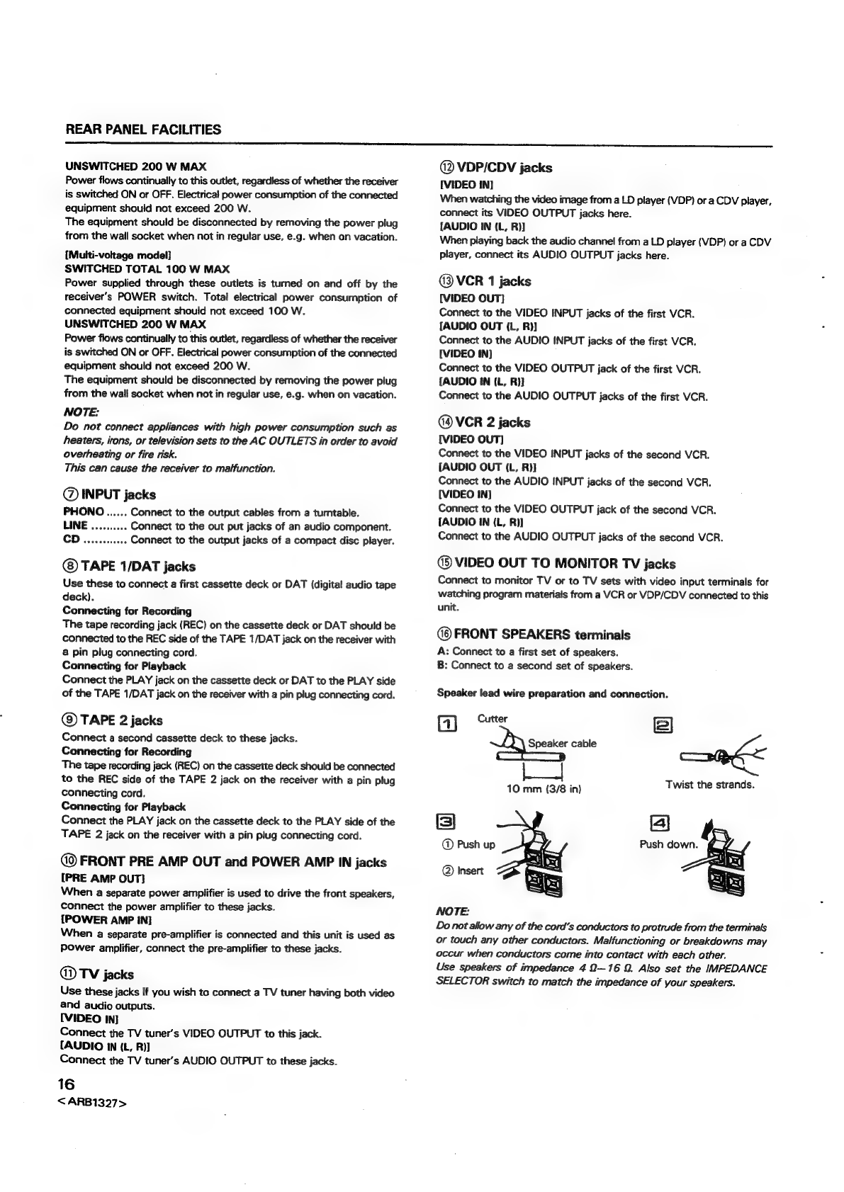
@
INPUT
jacks
PHONO......
Connect
to
the
output
cables
from
a
turntable.
LINE
..........
Connect
to
the
out
put
jacks
of
an
audio
component.
CD.
ceiccstines
Connect
to
the
output
jacks
of
a
compact
disc
player.
TAPE
1/DAT
jacks
Use
these
to
connect
a
first
cassette
deck
or
DAT
(digital
audio
tape
deck).
Connecting
for
Recording
The
tape
recording
jack
(REC)
on
the
cassette
deck
or
DAT
should
be
connected
to
the
REC
side
of
the
TAPE
1/DAT
jack
on
the
receiver
with
a
pin
plug
connecting
cord.
Connecting
for
Playback
Connect
the
PLAY
jack
on
the
cassette
deck
or
DAT
to
the
PLAY
side
of
the
TAPE
1/DAT
jack
on
the
receiver
with
a
pin
plug
connecting
cord.
@)
TAPE
2
jacks
Connect
a
second
cassette
deck
to
these
jacks.
Connecting
for
Recording
The
tape
recording
jack
(REC)
on
the
cassette
deck
should
be
connected
to
the
REC
side
of
the
TAPE
2
jack
on
the
receiver
with
a
pin
plug
connecting
cord.
Connecting
for
Playback
Connect
the
PLAY
jack
on
the
cassette
deck
to
the
PLAY
side
of
the
TAPE
2
jack
on
the
receiver
with
a
pin
plug
connecting
cord.
FRONT
PRE
AMP
OUT
and
POWER
AMP
IN
jacks
[PRE
AMP
OUT]
When
a
separate
power
amplifier
is
used
to
drive
the
front
speakers,
connect
the
power
amplifier
to
these
jacks.
[POWER
AMP
IN]
When
a
separate
pre-amplifier
is
connected
and
this
unit
is
used
as
Power
amplifier,
connect
the
pre-amplifier
to
these
jacks.
@®
TV
jacks
Use
these
jacks
if
you
wish
to
connect
a
TV
tuner
having
both
video
and
audio
outputs.
[VIDEO
INI
Connect
the
TV
tuner’s
VIDEO
OUTPUT
to
this
jack.
[AUDIO
IN
(L,
R))
Connect
the
TV
tuner’s
AUDIO
OUTPUT
to
these
jacks.
16
<ARB1327>
@
VDP/CDV
jacks
[VIDEO
IN]
When
watching
the
video
image
from
a
LD
player
(VDP)
or
a
CDV
player,
connect
its
VIDEO
OUTPUT
jacks
here.
{AUDIO
IN
(L,
R)]
When
playing
back
the
audio
channel
from
a
LD
player
(VDP)
or
a
CDV
player,
connect
its
AUDIO
OUTPUT
jacks
here.
@3
VCR
1
jacks
[VIDEO
OUT]
Connect
to
the
VIDEO
INPUT
jacks
of
the
first
VCR.
[AUDIO
OUT
(L,
R))
Connect
to
the
AUDIO
INPUT
jacks
of
the
first
VCR.
[VIDEO
IN)
Connect
to
the
VIDEO
OUTPUT
jack
of
the
first
VCR.
[AUDIO
IN
(L,
R)]}
Connect
to
the
AUDIO
OUTPUT
jacks
of
the
first
VCR.
VCR
2
jacks
[VIDEO
OUT)
Connect
to
the
VIDEO
INPUT
jacks
of
the
second
VCR.
[AUDIO
OUT
(L,
R)]
Connect
to
the
AUDIO
INPUT
jacks
of
the
second
VCR.
[VIDEO
IN)
Connect
to
the
VIDEO
OUTPUT
jack
of
the
second
VCR.
{AUDIO
IN
(L,
R)]
Connect
to
the
AUDIO
OUTPUT
jacks
of
the
second
VCR.
@®
VIDEO
OUT
TO
MONITOR
TV
jacks
Connect
to
monitor
TV
or
to
TV
sets
with
video
input
terminals
for
watching
program
materials
from
a
VCR
or
VDP/CDV
connected
to
this
unit.
FRONT
SPEAKERS
terminals
A:
Connect
to
a
first
set
of
speakers.
B:
Connect
to
a
second
set
of
speakers.
Speaker
lead
wire
preparation
and
connection.
ic
Cutter
2
ej
Speaker
cable
.
|
!
Re
y
4
;
10
mm
(3/8
in)
Twist
the
strands.
Push
down.
=
Push
up
@
Insert
NOTE:
Do
not
allow
any
of
the
cord’s
conductors
to
protrude
from
the
terminals
or
touch
any
other
conductors.
Malfunctioning
or
breakdowns
may
occur
when
conductors
come
into
contact
with
each
other.
Use
speakers
of
impedance
4
2—16
9.
Also
set
the
IMPEDANCE
SELECTOR
switch
to
match
the
impedance
of
your
speakers.
REAR
PANEL
FACILITIES
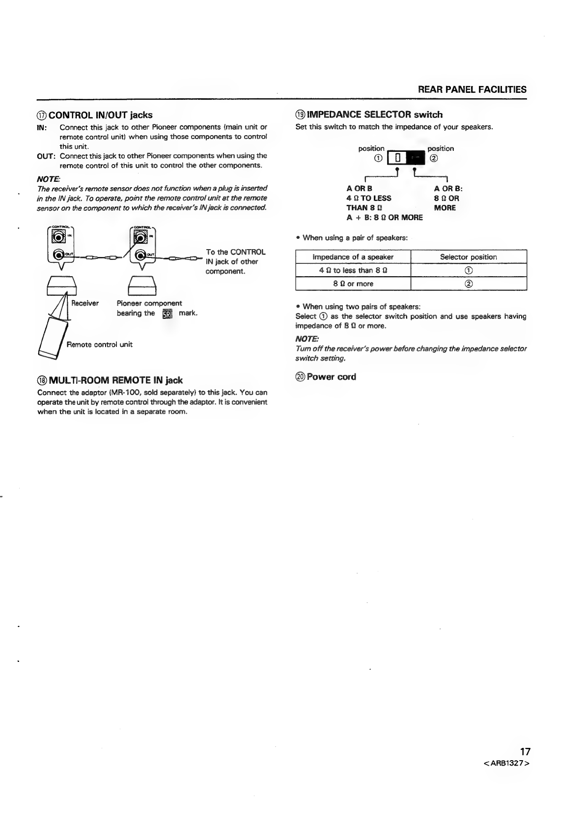
@)
CONTROL
IN/OUT
jacks
IN:
Connect
this
jack
to
other
Pioneer
components
(main
unit
or
remote
control
unit)
when
using
those
components
to
control
this
unit.
OUT:
Connect
this
jack
to
other
Pioneer
components
when
using
the
remote
control
of
this
unit
to
control
the
other
components.
NOTE:
The
receiver's
remote
sensor
does
not
function
when
a
plug
is
inserted
in
the
IN
jack.
To
operate,
point
the
remote
control
unit
at
the
remote
sensor
on
the
component
to
which
the
receiver's
IN
jack
is
connected.
To
the
CONTROL
IN
jack
of
other
component.
Receiver
Pioneer
component
bearing
the
mark.
Remote
control
unit
MULTI-ROOM
REMOTE
IN
jack
Connect
the
adaptor
(MR-100,
sold
separately)
to
this
jack.
You
can
operate
the
unit
by
remote
control
through
the
adaptor.
It
is
convenient
when
the
unit
is
located
in
a
separate
room.
@
IMPEDANCE
SELECTOR
switch
Set
this
switch
to
match
the
impedance
of
your
speakers.
position
position
®
@
A
ORB
A
ORB:
409
TO
LESS
8Q
OR
THAN
8
Q
MORE
A
+
B:
8
2
OR
MORE
¢
When
using
a
pair
of
speakers:
impedance
of
a
speaker
Selector
position
[enorme
|
¢
When
using
two
pairs
of
speakers:
Select
@
as
the
selector
switch
position
and
use
speakers
having
impedance
of
8
©
or
more.
NOTE:
Turn
off
the
receiver's
power
before
changing
the
impedance
selector
switch
setting.
Power
cord
17
<ARB1327>

FRONT
PANEL
FACILITIES
WD
PIONEER
avomoss
sremo
momvee
VSX-5900S
Se
mo
NMA
oo
a]
s
Se,
=
PANNA
heheh
=
.
E
acoustic
Lovoness
juli!
+>
a
Be
amin
rN
|
Win
UI
MINI
i
l
i
Hl
i
ull
EF
18
<ARB1327>
FRONT PANEL
FACILITIES
@)
POWER
STANDBY/ON
switch
This
is
the
switch
for
electric
power.
ON:
When
set
to
the
ON
position,
power
is
supplied
and
the
unit
becomes
operational.
STANDBY:
When
set
to
the
STANDBY
position,
the
main
power
flow
is
cut
and
the
unit
is
no
longer
fully
operational.
A
minute
flow
of
power
feeds
the
unit
to
maintain
operation
readiness.
On
the
multi-voltage
model,
the
indicator
on
the
MASTER
VOLUME
control
knob
lights
during
STANDBY.
[TIMER
ON/OFF
possible]
When
the
unit
is
switched
ON,
ON/OFF
control
can
be
performed
by
means
of
the
optional
timer.
NOTE:
When
the
power
is
initially
turned
ON,
muting
will
be
applied
to
prevent
sound
from
being
output
for
about
5
seconds.
@
SOUND
FIELD
MEMORY
buttons
MEMORY:
Pressing
this
button
will
result
in
the
memorization
of
the
sound
field
condition.
Press
again
to
cancel
this
mode.
SELECT:
¢
This
button
is
used
to
preset
the
five
sound
field
memories
(A—E).
©
This
button
is
also
used
to
recall
previously
set
sound
field
settings.
Each
time
you
press
the
button,
the
sound
field
setting
advances
in
the
order
shown
below.
ne
P:
The
sound
field
setting
previously
memorized
in
the
unit.
@
TEST
TONE
button
Operates
when
the
DOLBY
PRO
LOGIC
SURROUND
or
DOLBY
3CH
LOGIC
mode
is
selected.
When
the
button
is
turned
ON,
‘’TEST’
appears
on
the
display
section
and
a
test
tone
approximately
two
seconds
in
duration
is
generated
in
all
channels
in
succession.
@
CENTER
MODE
button
This
operates
if
DOLBY
PRO
LOGIC
SURROND
or
DOLBY
3CH
LOGIC
is
ON.
The
setting
changes
in
the
order
listed
below
each
time
you
press
the
button.
NORMAL
-—
Use
this
setting
when
a
small
enclosure
center
channei
speaker
incapable
of
reproducing
frequencies
below
100Hz
is
connected.
;
PHANTOM
—
Use
this
setting
when
no
center
channel
speaker
is
connected
(DOLBY
PRO
LOGIC
SURROUND).
WIDE
—
Use
this
setting
when
a
large
enclosure
center
channel
speaker
capable
of
reproducing
frequencies
below
100Hz
is
connected.
NOTE
FOR
DOLBY
PRO
LOGIC
SURROUND:
¢
/f
no
center
speaker
is
used,
then
mono
signals
and
center
channel
Signal
components
will
not
be
reproduced
at
positions
other
than
the
PHANTOM
position.
@)
CENTER
LEVEL
(+,
-)
buttons
Use
these
buttons
to
adjust
the
center
speaker
sound
level
to
the
level
of
the
front
speakers.
Operate
when
DOLBY
PRO
LOGIC
SURROUND
or
DOLBY
3CH
LOGIC
mode
is
on.
After
adjustment,
use
the
MASTER
VOLUME
control
to
adjust
the
overall
sound
to
a
suitable
level.
—
:
Lowers
the
center
speaker
sound
level.
+
:
Raises
the
center
speaker
sound
level.
©
REAR
LEVEL
(-,
+)
buttons
Operate
only
when
the
surround
mode
is
on.
These
buttons
are
used
to
preset
the
sound
level
difference
between
the
front
and
rear
speakers.
tn
this
way,
after
presetting
the
difference,
the
overall
volume
of
the
front
and
surround
speakers
can
be
changed
using
the
MASTER
VOLUME
control,
while
still
maintaining
the
sound
volume
differential.
—
:
Rear
speaker
volume
is
reduced.
+
:
Rear
speaker
volume
is
increased.
Press
—
and
+
together
to
restore
front
and
surround
to
the
default
volume
balance
setting.
@
MASTER
BAL
buttons
Use
them
to
adjust
the
sound
balance
between
left
and
right
speakers.
L:
Press
to
decrease
the
sound
on the
right
side.
R:
Press
to
decrease
the
sound
on
the
left
side.
Press
L
and
R
together
to
bring
the
volume
balance
back
to
center.
MUTING
button
Press
to
temporarily
cut
off
the
sound
volume.
The
display
section
MUTING
indicator
will
flash.
When
pressed
again,
the
sound
will
return
to
its
previous
level.
@
MASTER
VOLUME
control
Use
it
to
simultaneously
adjust
the
sound
volume
from
the
front,
center
and
rear
speakers.
When
you
adjust
volume
by
remote
control,
the
indicator
above
the
knob
flashes.
RETURN
button
Pressing
this
button
returns
the
receiver
to
the
following
settings,
the
sound
level
being
controlled
by
MASTER
VOLUME
control
knob.
¢
TAPE
2
MONITOR
OFF
¢
SURROUND
MODE
OFF
©
MUTING
OFF
¢
BALANCE
CENTER
@
INPUT
SELECTOR
TUNER
¢
STATION
CALL
1
CH*
*
When
a
station
is
not
memorized
in
1
CH,
station
search
will
automatically
proceed
from
the
frequency
displayed.
NOTE:
/f
no
sound
is
output
after
the
RETURN
button
is
pressed,
make
sure
that
SPEAKERS
buttons
are
turned
on.
@
V-SIGNAL
(VIDEO
SIGNAL)
SELECTOR
button
When
recording
simulcast
programs,
the
recorded
image
can
be
selected
from
among
VCR
1,
VCR
2,
VDP
and
TV.
fo
ee
The
current
setting
is
shown
by
an
indicator
on
the
display
section.
(@
PHONES
jack
Connect
the
plug
on
your
headphones
to
this
jack.
Set
all
SPEAKERS
A,
B
and
CENTER/REAR
buttons
to
OFF
if
you
want
to
cut
the
sound
from
speakers
and
listen
to
it
only
through
the
headphones.
19
<ARB1327>
FRONT
PANEL
FACILITIES
@3
STATION
CALL
buttons
Up
to
30
FM
or
AM
stations
can
be
preset
at
random.
These
buttons
are
used
to
preset
and
recall
desired
broadcasting
stations,
FM
AUTO/MONO
mode.
NOTE:
:
Pressing
a
BAND
selector
button
or
STATION
CALL
button
will
select
TUNER
as
the
source,
regardless
of
what
other
listening
source
or
function
was
selected.
BAND
selector
buttons
FM:
Press
for
FM
reception.
AM:
Press
for
AM
reception.
@®
SPEAKERS
buttons
(A,
B,
CENTER/REAR)
ON/OFF
buttons
for
the
A,
B
and
CENTER/REAR
speaker
systems.
An
indicator
on
the
display
section
lights
when
any
of
these
buttons
is
set
to
ON.
TUNING
buttons
+:
Performs
tuning
from
the
currently
displayed
station
frequency
in
ascending
frequency
order.
—:
Performs
tuning
in
order
to
descending
frequencies.
@
SIMULATED
STEREO
button
Press
to
produce
a
simulated
stereo
effect
when
listening
to
monaural
sources
(for
example,
normal
AM
or
TV
broadcasts).
“SIMULATED
STEREO”
appears
on the
display
section.
NOTE:
©
This
effect
is
not
produced
through
the
rear
speakers.
©
Use
with
the
SURROUND
MODE
in
the
SIMULATED
SURROUND
position
or
OFF
position
(There
is
no
effect
in
the
STADIUM,
DOLBY
3CH
LOGIC
and
DOLBY
PRO
LOGIC
SURROUND
positions).
With
a
monaural
source,
it
is
more
effective
if
used
together
with
SIMULATED
SURROUND.
MEMORY
button
When
the
unit
is
in
the
frequency
display
mode,
pressing
this
button
will
result
in
the
memorization
of
the
current
broadcast
band,
reception
frequency,
and
FM
AUTO/MONO
mode.
This
button
is
also
used
to
input
custom
memory
names
(see
page
24).
FM
MODE
AUTO/MONO
selector
button
Use
to
select
the
auto
stereo
mode
or
monaural
mode
when
listening
to
FM
broadcasts.
The
monaural
mode
has
been
selected
when
the
FM
MONG
indicator
in
the
display
section
is
lit.
Auto
stereo
mode:
Normally,
leave
in
this
mode
for
reception.
When
a
stereo
FM
broadcast
is
received,
it
will
be
automatically
reproduced
in
stereo.
Monaural
mode:
When
receiving
distant
stations
or
stations
with
weak
broadcast
signals,
the
input
signa!
may
be
weak,
thus
resulting
in
increased
noise
during
FM
stereo
broadcasts.
In
this
event,
setting
the
receiver
to
the
monaural
mode
will
reduce
the
noise.
In
this
case,
however,
FM
stereo
broadcasts
will
be
reproduced
in
monaural
sound.
NOTE:
This
button
has
no
effect
on
reception
of
AM
broadcasts.
TUNING
buttons
AUTO/MANUAL
TUNING
selector
button:
This
button
is
used
to
select
the
tuning
mode.
The
AUTO
indicator
lights
when
the
AUTO
tuning
mode
has
been
selected.
AUTO
tuning
When
the
—
or
+
TUNING
button
is
pressed,
the
receiver
automatically
Scans
the
broadcast
station
frequencies.
When
a
broadcast
is
detected,
the
scanning
stops
at
that
frequency.
20
<ARB1327>
NOTE:
Pressing
the
TUNING
button
(~
or
+}
while
scanning
is
taking
place
causes
scanning
to
stop.
MANUAL
tuning
This
lets
you
manually
tune
to
particular
broadcast
frequencies.
Each
press
of
the
+
or
—
button
raises
or
lowers
the
frequency
by
one
tuning
step.
For
continuous
scanning,
keep
the
button
pressed,
then
release
it
to
stop
scanning.
‘
DIRECT
ACCESS
TUNING
button:
When
this
button
is
pressed,
the
STATION
CALL
buttons
function
as
ten-key
number
buttons
for
direct
input
of
the
desired
reception
frequency.
Press
again
to
cancel
this
mode.
If
the
input
station
falls
outside
of
the
receiver's
tuning
range,
the
display
section
will
display
a
message:
“UPPER”
if
the
frequency
is
too
high
and
‘‘LOWER”’
if it
is
too
low
(see
page
22).
HITS
(Hyper
Intelligent
Tuning
System)
button:
°
If
the
HITS
button
is
pressed
during
input
of
numbers
for
DIRECT
ACCESS
tuning,
the
receiver
sets
the
remaining
digits
which
have
not
yet
been
input
to
“0,”
searches
for
the
corresponding
frequencies,
and
stops
on the
first
station
it
finds.
©
If
the
HITS
button
is
pressed
at
the
currently
displayed
station
frequency,
the
receiver
searches
up
and
down
the
frequency
for
the
next
station
(The
SEARCH
indicator
in
the
display
section
lights
at
this
time.)
and
stops
at
the
first
one
it
finds.
{FM)
-1
MHz
START
+1/MHz
NOTE:
®
The
system
searches
for
stations
within
successive
1
MHz
ranges
for
FM
and 100
kHz
ranges
for
AM.
During
DIRECT
ACCESS
tuning,
it
searches
up
and
down
for
a
station
until
it
reaches
the
edges
of
the
band.
If
no
receivable
station
is
found
within
the
band
range,
the
receiver
returns
to
the
state
it
was
in
before
the
HITS
button
was
pressed.
©
/f
the
upper
(or
lower)
frequency
limit
of
the
receiver
is
encountered
during
HITS
operation,
the
receiver
stops
searching
in
that
direction
but
continues
to
search
in
the
other.
@)
CUSTOM
MEMORY
buttons
Stations
can
be
assigned
to
STATION
CALL
buttons
according
to
the
genre
of
material
broadcast
(for
example,
ROCK,
JAZZ,
etc.).
You
can
recall
a
particular
genre,
and
scan
all
the
stations
of
that
genre
with
Memory
Scan
until
you
reach
the
desired
one.
The
initial
settings
are
ROCK,
POP,
JAZZ,
NEWS,
and
PARTY.
NAME
button
Change
the
name
of
a
genre
with
this
button.
SELECT
button
Recall
a
genre
name
with
this
button.
SCAN
button
Use
this
button
to
carry
out
Memory
Scan
within
a
genre
recalled
with
the
SELECT
button.
If
it
is
pressed
when
“TUNER”
is
displayed,
Memory
Scan
of
successive
STATION
CALL
NUMBERS
and
not
genre
will
occur.
Table of contents


