4. CIRCUITDESCRIPTIONS
4.1 MAJORFUNCTIONS
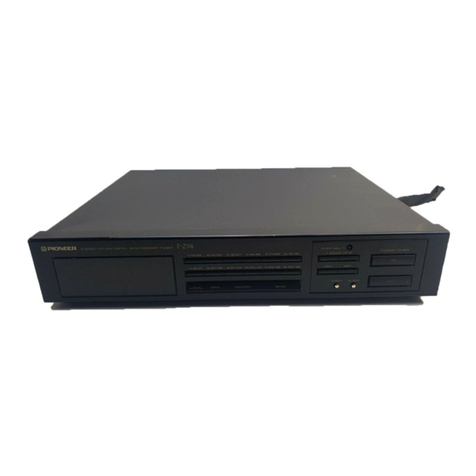
The F-7 is a PLL digital synthesizedtuner refer-
enced to a crystal oscillator. Its main functions are
as
follows:
1. Frequency
Range
FM: 87.5MHz to 108.0MH2in 50kHz steps.
AM: 522kHzto 1602kHz in 9kHz stePs.
2. Tuning
o Tuning is by an UP or DOWN key. Pressing
the
key once changes
frequency 1 step (9kHz in the
AM band, 50kHz in the FM band). Holding the
UP or DO\ryN key depressed causes the fre'
quencybandsto be scanned.
o Positioning the TUNING MODE switch to
AUTO and pressing
the UP or DO\ilN key once
causes
the unit to go into the auto search
tuning
mode. In this mode, the unit automatically
scans the frequency band, with scan stopping
at, and tuning into any broadcast station trans-
mitting a signal exceeding a prescribed level of
strength.
o Pressing the STATION CALL key causesthe
unit to directly tune to a frequency preset into
the unit.
3. Memory
o Up to 6 FM and 6 AM frequenciescan be preset
into the memory.
o A special memory holds the frequency of the
station tuned at the time the power supply is
cut OFF. \ttlhenpower is restored to the unit'
tuning is automatically made to that station'
4. Indicators
. Frequency is displayed by a ?-segment LED
numeric display. Five digits are used for FM
tuning and four digiLs
for AM tuning.
o Signal strength is indicated by the LED 5-point
indicator.
o FM and AM bandindicator.
o A flashing
bandindicator, indicates
that the unit
isin "memory write" (preset)status'
o STATION indicators(memory address).
o FM STEREOrecePtion
indicator.
4.2 FMTUNER
SECTION
Front-End
The FM front-end uses
adual-gateMOS FET RF
amplifier (single stage), and variable capacitance
diodes the equivalent of a 3-gangedtuning capacit-
or. The local oscillator usesanoutput buffer amp
to maintain stability during strong signalreception.
The local oscillator signal is input into the syn-
thesizer circuit and compared with the reference
signal, and the resulting tuning voltage is applied
to the variable capacitance diodes where it be-
comes the oscillator frequency (or tuning frequen-
cv).
lF Amplifier andDetector
This section consists of two ICs and two dual-
element ceramic filters. The first stage IC
(M5215L) is a single-stagedifferential amplifier
current-limiting limiter, and the second stage is
made up of the FM IF system IC (PA3007-A)
(consisting of an IF limiter amplifrer, quadrature
detector,and meter drive).
Multiplex Decoder
This section consists of IC (PA40O6-A), and
contains the PLL system switching signalgenerator
circuit, chopper type MPX decoder, pilot signal
automatic canceUer, stereo auto selector, VCO
killer circuit, muting amplifier, muting control
circuit, and stereo reception indicator circuit'
The chopper type switching circuit either does
or does not establish a signal, thereby generating
no noise
or distortion.
4.3 AM TUNER SECTION
The AM tuner section uses IC (HA1138) and
variable capacitance diodes the equivalent of a
2-ganged
tunin
g caPacitor.
The local oscillator signal is input into the syn-
thesizer circuit and compared with the reference
signal. The resulting tuning voltage is applied to
the variable capacitance diodes where it becomes
the oscillator frequency (tuning frequency).
To improve strong signal reception stability,
the IC has a built-in AGC (automatic gain control)
in addition to a bar antenna and damping coil,
all controlled by an FET in responseto the RF
amplifier outPut level.
