manuals.online logo
Brands
  1. Home
  2. •
  3. Brands
  4. •
  5. Pioneer
  6. •
  7. Car Receiver
  8. •
  9. Pioneer FH-X720BT User manual

Pioneer FH-X720BT User manual

This manual suits for next models

1

Other Pioneer Car Receiver manuals

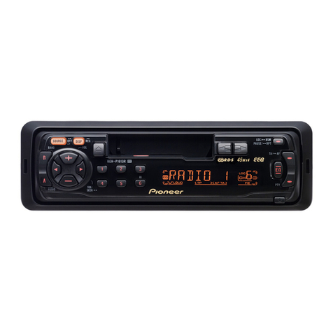
Pioneer CDX-P670 User manual

Pioneer

Pioneer CDX-P670 User manual

Pioneer KEH-P525 User manual

Pioneer

Pioneer KEH-P525 User manual

Pioneer AVH-X8650BT User manual

Pioneer

Pioneer AVH-X8650BT User manual

Pioneer DEH-1100 User manual

Pioneer

Pioneer DEH-1100 User manual

Pioneer AVH-P6400CD User manual

Pioneer

Pioneer AVH-P6400CD User manual

Pioneer KEH-1940 User manual

Pioneer

Pioneer KEH-1940 User manual

Pioneer DEH-S4250BT User manual

Pioneer

Pioneer DEH-S4250BT User manual

Pioneer DEH-1250MPG User manual

Pioneer

Pioneer DEH-1250MPG User manual

Pioneer DEH-P4600MP User manual

Pioneer

Pioneer DEH-P4600MP User manual

Pioneer DEH-1300 User manual

Pioneer

Pioneer DEH-1300 User manual

Pioneer DEH-P3370XM UC User manual

Pioneer

Pioneer DEH-P3370XM UC User manual

Pioneer DEH-P690UB - Premier Radio / CD User manual

Pioneer

Pioneer DEH-P690UB - Premier Radio / CD User manual

Pioneer DEH-X2600UI User manual

Pioneer

Pioneer DEH-X2600UI User manual

Pioneer DEH-P80MP User manual

Pioneer

Pioneer DEH-P80MP User manual

Pioneer DXT-X2669UI User manual

Pioneer

Pioneer DXT-X2669UI User manual

Pioneer AVH-P8450BT User manual

Pioneer

Pioneer AVH-P8450BT User manual

Pioneer DEH-X8500BH User manual

Pioneer

Pioneer DEH-X8500BH User manual

Pioneer XDV-P6 - DVD Changer - in-dash User manual

Pioneer

Pioneer XDV-P6 - DVD Changer - in-dash User manual

Pioneer FX-MG6096ZH User manual

Pioneer

Pioneer FX-MG6096ZH User manual

Pioneer DEH-M6156ZH User manual

Pioneer

Pioneer DEH-M6156ZH User manual

Pioneer KEH-1906ZZ/X1H/UC User manual

Pioneer

Pioneer KEH-1906ZZ/X1H/UC User manual

Pioneer KEH-P5950 User manual

Pioneer

Pioneer KEH-P5950 User manual

Pioneer MVH-1490UB User manual

Pioneer

Pioneer MVH-1490UB User manual

Pioneer KEH-P4950J User manual

Pioneer

Pioneer KEH-P4950J User manual

Popular Car Receiver manuals by other brands

Linear Series LS5050 Operation and installation manual

Linear Series

Linear Series LS5050 Operation and installation manual

Kenwood KRC-160 instruction manual

Kenwood

Kenwood KRC-160 instruction manual

Sony XR-CA430X Service manual

Sony

Sony XR-CA430X Service manual

T+A Elektroakustik K1 CD-RECEIVER operating instructions

T+A Elektroakustik

T+A Elektroakustik K1 CD-RECEIVER operating instructions

SoundMax SM-CDM1052 instruction manual

SoundMax

SoundMax SM-CDM1052 instruction manual

Xtrons HD107HD user manual

Xtrons

Xtrons HD107HD user manual

Mopar RB3 manual

Mopar

Mopar RB3 manual

Clarion ADDZEST DMZ615 owner's manual

Clarion

Clarion ADDZEST DMZ615 owner's manual

Sony XAV-601BT Specifications

Sony

Sony XAV-601BT Specifications

PIE GM12-POD/S Operation manual

PIE

PIE GM12-POD/S Operation manual

Hyundai H-910H instruction manual

Hyundai

Hyundai H-910H instruction manual

Sony XR-C6100 Service manual

Sony

Sony XR-C6100 Service manual

Sony CDX-L600X - Fm/am Compact Disc Player Installation/connections

Sony

Sony CDX-L600X - Fm/am Compact Disc Player Installation/connections

Motorola VWA63 Service manual

Motorola

Motorola VWA63 Service manual

Sound Storm STM93R user manual

Sound Storm

Sound Storm STM93R user manual

Nextar D3201 instruction manual

Nextar

Nextar D3201 instruction manual

Alpine CDE-163BT owner's manual

Alpine

Alpine CDE-163BT owner's manual

Kenwood KDC-X303 quick start guide

Kenwood

Kenwood KDC-X303 quick start guide

manuals.online logo
manuals.online logoBrands
  • About & Mission
  • Contact us
  • Privacy Policy
  • Terms and Conditions

Copyright 2025 Manuals.Online. All Rights Reserved.

19En
English
WARNING
•Use speakers over 50 W (output value)
and between 4 Ω to 8 Ω (impedance
value). Do not use 1 Ω to 3 Ω speakers for
this unit.
•The black cable is ground. When
installing this unit or power amp (sold
separately), make sure to connect the
ground wire first. Ensure that the ground
wire is properly connected to metal parts
of the car’s body. The ground wire of the
power amp and the one of this unit or
any other device must be connected to
the car separately with different screws. If
the screw for the ground wire loosens or
falls out, it could result in fire, generation
of smoke or malfunction.
Important
•When installing this unit in a vehicle
without an ACC (accessory) position on
the ignition switch, failure to connect the
red cable to the terminal that detects
operation of the ignition key may result
in battery drain.
•Use this unit with a 12-volt battery and
negative grounding only. Failure to do so
may result in a fire or malfunction.
•To prevent a short-circuit, overheating or
malfunction, be sure to follow the
directions below.
– Disconnect the negative terminal of the
battery before installation.
– Secure the wiring with cable clamps or
adhesive tape. Wrap adhesive tape
around wiring that comes into contact
with metal parts to protect the wiring.
– Place all cables away from moving parts,
such as the shift lever and seat rails.
– Place all cables away from hot places,
suchas near the heater outlet.
– Do not connect the yellow cable to the
battery by passing it through the hole
to the engine compartment.
– Cover any disconnected cable
connectors with insulating tape.
– Do not shorten any cables.
– Never cut the insulation of the power
cable of this unit in order to share the
power with other devices. The current
capacity of the cable is limited.
– Use a fuse of the rating prescribed.
– Never wire the negative speaker cable
directly to ground.
– Never band together negative cables of
multiple speakers.
•When this unit is on, control signals are
sent through the blue/white cable.
Connect this cable to the system remote
control of an external power amp or the
vehicle’s auto-antenna relay control
terminal (max. 300mA 12 V DC). If the
Connections/Installation
Connections
Ground wire POWER AMP
Other devices
(Another electronic device
in the car)
Metal parts of
car’s body
*1 Not supplied for this unit
ACC position No ACC position
vehicle is equipped with a glass antenna,
connect it to the antenna booster power
supply terminal.
•Never connect the blue/white cable to
the power terminal of an external power
amp. Also, never connect it to the power
terminal of the auto antenna. Doing so
may result in battery drain or a
malfunction.
This unit
Microphone (4 m)
SiriusXM Connect Vehicle Tuner input
Power cord input
Microphone input
Rear output
Front output
Antenna input
Fuse (10 A)
Wired remote input
Hard-wired remote control adapter can
be connected (sold separately).
Subwoofer output
SiriusXM Connect Vehicle Tuner (sold
separately)
Power cord input
Microphone input
Microphone (4 m)
Rear output or subwoofer output
Front output
Antenna input
Fuse (10 A)
Wired remote input
Hard-wired remote control adapter can
be connected (sold separately).
Power cord input
Rear output or subwoofer output
Front output
Antenna input
Fuse (10 A)
Wired remote input
Hard-wired remote control adapter can
be connected (sold separately).
Power cord
Perform these connections when not
connecting a rear speaker lead to a
subwoofer.
FH-X820BS
FH-X720BT/X721BT
FH-X520UI
20En
Perform these connections when using a
subwoofer without the optional amplifier.
To power cord input
Left
Right
Front speaker
Rear speaker
White
White/black
Gray
Gray/black
Green
Green/black
Violet
Violet/black
Black (chassis ground)
Connect to a clean, paint-free metal
location.
Yellow
Connect to the constant 12 V supply
terminal.
Red
Connect to terminal controlled by the
ignition switch (12 V DC).
Blue/white
Connect to the system control terminal
ofthe power amp or auto-antenna relay
control terminal (max. 300 mA 12 V DC).
Subwoofer (4 Ω)
When using a subwoofer of 70 W (2 Ω),
be sure to connect the subwoofer to the
violet and violet/black leads of this unit.
Do not connect anything to the green
and green/black leads.
Not used.
Subwoofer (4 Ω) × 2
Orange/white
Connect to a car’s illumination signal.
Yellow/black (Only for FH-X520UI)
If you use equipment with a Mute
function, wire this lead to the Audio
Mute lead on that equipment. If not,
keep the Audio Mute lead free of any
connections.
NOTE
Change the initial menu of this unit. Refer
to[SP-P/O MODE] (page 7). The subwoofer
output of this unit is monaural.
Power amp (sold separately)
Perform these connections when using the
optional amplifier.
System remote control
Connect to blue/white cable.
Power amp (sold separately)
Connect with RCA cables (sold
separately)
To rear output
Rear speaker
To front output
Front speaker
To subwoofer output
Subwoofer
To rear output or subwoofer output
Rear speaker or subwoofer
Important
•Check all connections and systems before
final installation.
•Do not use unauthorized parts as this
may cause malfunctions.
•Consult your dealer if installation requires
drilling of holes or other modifications to
the vehicle.
•Do not install this unit where:
–it may interfere with operation of the
vehicle.
–it may cause injury to a passenger as a
result of a sudden stop.
•The semiconductor laser will be damaged
if it overheats. Install this unit away from
hot places such as near the heater outlet.
•Optimum performance is
obtained when the unit is
installed at an angle of less
than 60°.
•When installing, to ensure proper heat
dispersal when using this unit, make sure
you leave ample space behind the rear
panel and wrap any loose cables so they
are not blocking the vents.
FH-X820BS
FH-X720BT/X721BT/X520UI
Installation
Leave ample
space 5 cm
5 cm
21En
English
DIN Rear-mount
1Determine the appropriate position
where the holes on the bracket and
the side of the unit match.
2Tighten the screws on each side.
Screw
Mounting bracket
Dashboard or console
•Use either truss (5 mm × 8 mm) or
flush surface (5 mm × 9 mm) screws,
depending on the bracket screw
holes.
(Only for FH-X820BS/X720BT/X721BT)
The microphone should be placed directly
in front of the driver at a suitable distance
to pick up their voice clearly.
CAUTION
It is extremely dangerous to allow the
microphone lead to become wound
around the steering column or shift lever.
Be sure to install the microphone in such a
way that it will not obstruct driving. It is
recommended to use the clamps (sold
separately) to arrange the lead.
To install on the sun visor
1Fit the microphone lead into the
groove.
2Install the microphone clip on the sun
visor.
Lowering the sun visor reduces the
voice recognition rate.
To install on the steering
column
1Slide the microphone base to detach it
from the microphone clip.
Microphone
Microphone clip
Microphone base
Installing the microphone
Microphone lead
Groove
Microphone clip
2Install the microphone on the rear side
of the steering column.
Double-sided tape
26En
General
Power source: 14.4 V DC (10.8 V to 15.1 V
allowable)
Grounding system: Negative type
Maximum current consumption: 10.0 A
Dimensions (W × H × D):
D
Chassis: 178 mm × 100 mm × 165 mm
(7 in. × 3-7/8 in. × 6-1/2 in.)
Nose: 170 mm × 96 mm × 18 mm (6-
3/4 in. × 3-3/4 in. × 3/4 in.)
Weight: 1.2 kg (2.6 lbs)
Audio
Maximum power output:
50 W × 4
70 W × 1/2 Ω (for subwoofer)
Continuous power output:
22 W × 4 (50 Hz to 15 000 Hz, 5 %
THD, 4 Ω load, both channels driven)
Load impedance: 4 Ω (4 Ω to 8 Ω allowable)
Preout maximum output level: 2.0 V
Loudness contour: +10 dB (100 Hz), +6.5
dB (10 kHz) (volume: –30 dB)
Equalizer (5-Band Graphic Equalizer):
Frequency: 80 Hz/250 Hz/800 Hz/2.5
kHz/8 kHz
Equalization range: ±12 dB (2 dB step)
Subwoofer (mono):
Frequency: 50 Hz/63 Hz/80 Hz/100
Hz/125 Hz/160 Hz/200 Hz
Slope: –6 dB/oct, –12 dB/oct
Gain: +6 dB to –24 dB
Phase: Normal/Reverse
CD player
System: Compact disc audio system
Usable discs: Compact disc
Signal-to-noise ratio: 94 dB (1 kHz) (IHF-A
network)
Number of channels: 2 (stereo)
MP3 decoding format: MPEG-1 & 2 Audio
Layer 3
WMA decoding format: Ver. 7, 7.1, 8, 9, 10,
11, 12 (2 ch audio) (Windows Media
Player)
WAV signal format: Linear PCM & MS
ADPCM (Non-compressed)
USB
USB standard specification: USB 2.0 full
speed
Maximum current supply: 1 A
USB Class: MSC (Mass Storage Class)
File system: FAT12, FAT16, FAT32
MP3 decoding format: MPEG-1 & 2 Audio
Layer 3
WMA decoding format: Ver. 7, 7.1, 8, 9, 10,
11, 12 (2 ch audio) (Windows Media
Player)
WAV signal format: Linear PCM & MS
ADPCM (Non-compressed)
FM tuner
Frequency range: 87.9 MHz to 107.9 MHz
Usable sensitivity: 11 dBf (0.8 μV/75 Ω,
mono, S/N: 30 dB)
Signal-to-noise ratio: 72 dB (IHF-A network)
AM tuner
Frequency range: 530 kHz to 1 710 kHz
Usable sensitivity: 25 μV (S/N: 20 dB)
Signal-to-noise ratio: 62 dB (IHF-A network)
Specifications Bluetooth
(FH-X820BS/X720BT/X721BT)
Version: Bluetooth 3.0 certified
Output power: +4 dBm Maximum (Power
class 2)
Bluetooth profiles:
GAP (Generic Access Profile)
SDAP (Service Discovery Application
Profile)
OPP (Object Push Profile)
HFP (Hands Free Profile) 1.6
PBAP (Phone Book Access Profile)
A2DP (Advanced Audio Distribution
Profile)
AVRCP (Audio/Video Remote Control
Profile) 1.5
SPP (Serial Port Profile) 1.1
CEA2006 Specifications
Power output: 14 W RMS × 4 Channels (4 Ω
and 1 % THD+N)
S/N ratio: 91 dBA (reference: 1 W into 4 Ω)
NOTE
Specifications and the design are subject
to modifications without notice.
<
=