manuals.online logo
Brands
  1. Home
  2. •
  3. Brands
  4. •
  5. Pioneer
  6. •
  7. CD Player
  8. •
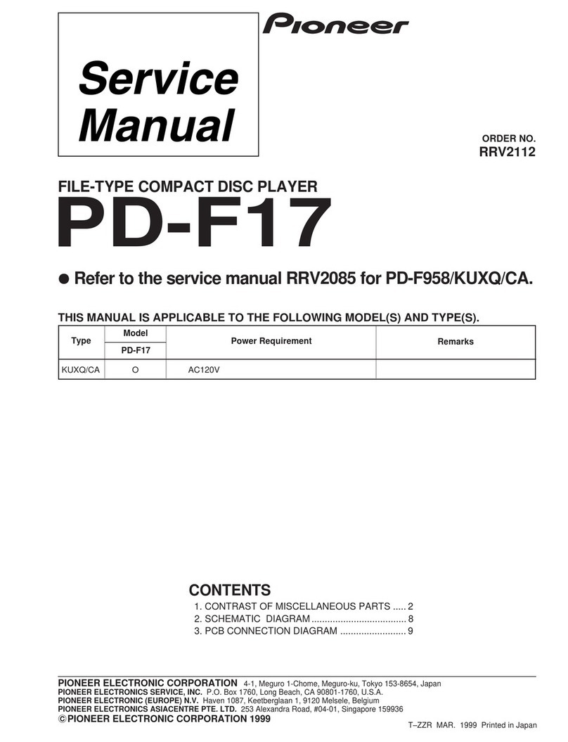
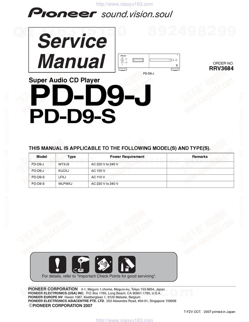
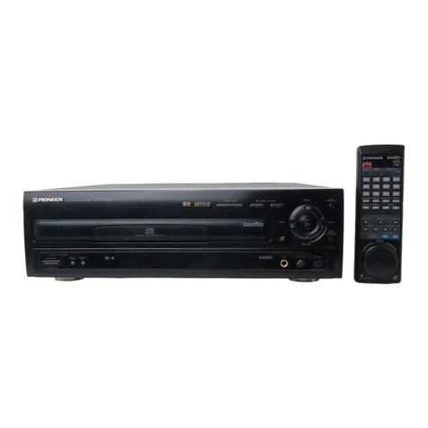
  9. Pioneer PD-S904 User manual

Pioneer PD-S904 User manual

This manual suits for next models

1

Other Pioneer CD Player manuals

Pioneer PD-30-K/-S User manual

Pioneer

Pioneer PD-30-K/-S User manual

Pioneer PD-M427 Building instructions

Pioneer

Pioneer PD-M427 Building instructions

Pioneer DEH-P6400 User manual

Pioneer

Pioneer DEH-P6400 User manual

Pioneer PD-M90X User manual

Pioneer

Pioneer PD-M90X User manual
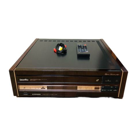
Pioneer XC-LA21 User manual

Pioneer

Pioneer XC-LA21 User manual

Pioneer CDJ-1000 User manual

Pioneer

Pioneer CDJ-1000 User manual

Pioneer PD-C5 User manual

Pioneer

Pioneer PD-C5 User manual

Pioneer PD-S602 User manual

Pioneer

Pioneer PD-S602 User manual

Pioneer LaserDisc CLD-1450 User manual

Pioneer

Pioneer LaserDisc CLD-1450 User manual

Pioneer CLD-3090 User manual

Pioneer

Pioneer CLD-3090 User manual

Pioneer PDR-509 User manual

Pioneer

Pioneer PDR-509 User manual

Pioneer PD-10AE User manual

Pioneer

Pioneer PD-10AE User manual

Pioneer PD-M701 User manual

Pioneer

Pioneer PD-M701 User manual

Pioneer PD-S601 User manual

Pioneer

Pioneer PD-S601 User manual

Pioneer PD-70AE User manual

Pioneer

Pioneer PD-70AE User manual

Pioneer PR-8210-A User manual

Pioneer

Pioneer PR-8210-A User manual

Pioneer PD-F25 User manual

Pioneer

Pioneer PD-F25 User manual

Pioneer SCSI-2 User manual

Pioneer

Pioneer SCSI-2 User manual

Pioneer CLD-2850 User manual

Pioneer

Pioneer CLD-2850 User manual

Pioneer DEH-59DH User manual

Pioneer

Pioneer DEH-59DH User manual

Pioneer PD-T303 User manual

Pioneer

Pioneer PD-T303 User manual

Pioneer CDJ-400 - Cd/Media Player User manual

Pioneer

Pioneer CDJ-400 - Cd/Media Player User manual

Pioneer DEH-P8100R User manual

Pioneer

Pioneer DEH-P8100R User manual

Pioneer PD-30-K User manual

Pioneer

Pioneer PD-30-K User manual

Popular CD Player manuals by other brands

Arcam CD23 Handbook

Arcam

Arcam CD23 Handbook

Sanyo MCD-Z1F Service manual

Sanyo

Sanyo MCD-Z1F Service manual

JVC RC-ST3SL instructions

JVC

JVC RC-ST3SL instructions

Technics SL-P9066 operating instructions

Technics

Technics SL-P9066 operating instructions

Marantz HD-CD1 quick start guide

Marantz

Marantz HD-CD1 quick start guide

Sony DVP-FX850 Service manual

Sony

Sony DVP-FX850 Service manual

Philips AZ1140 Instrukcja obs?ugi

Philips

Philips AZ1140 Instrukcja obs?ugi

Alpine 7909 owner's manual

Alpine

Alpine 7909 owner's manual

JVC CH-X350 instructions

JVC

JVC CH-X350 instructions

RCA RP-7923 instruction manual

RCA

RCA RP-7923 instruction manual

Philips Shockproof AX2102 brochure

Philips

Philips Shockproof AX2102 brochure

Philips CD582 user manual

Philips

Philips CD582 user manual

Philips AZ 6821 operating manual

Philips

Philips AZ 6821 operating manual

Lasonic MSU-2020 user manual

Lasonic

Lasonic MSU-2020 user manual

Denon DCD-1420 Service manual

Denon

Denon DCD-1420 Service manual

Panasonic SJ-MR100 operating instructions

Panasonic

Panasonic SJ-MR100 operating instructions

Onkyo DX-7210 instruction manual

Onkyo

Onkyo DX-7210 instruction manual

Cambridge Audio SONATA CD30 manual 

Cambridge Audio

Cambridge Audio SONATA CD30 manual 

manuals.online logo
manuals.online logoBrands
  • About & Mission
  • Contact us
  • Privacy Policy
  • Terms and Conditions

Copyright 2025 Manuals.Online. All Rights Reserved.

Y
PIONEER’
The
Art
of
Entertainment
Service
Manual
COMPACT
DISC
PLAYER
PD-S904
PD-S904-G
THIS
MANUAL
IS
APPLICABLE
TO
THE
FOLLOWING
MODEL(S)
AND
TYPE(S).
Type
ae
Power
Requirement
The
voltage
can
be
converted
by
following
method.
Se
oe
Trew
[Oo
|
0
[acem=zov
ican
awe
a
SO
|
,
ee
eee
ORDER
NO.
RRV1284
AC220
—
230V/230
—
240V
With
the
voltage
selector
AC110V/120
~
127V/220V/240V
With
the
voltage
selector
*
:
Alter
the
wiring
of
the
Power-supply
block
at
the
primary
winding
of
power
transformer
referring
to
the
“Line
Voltage
Selection”
described
in
Service
Manual.
CONTENTS
1.
SAFETY
INFORMATION
.....0000
cee
teeters
2
2.
EXPLODED
VIEWS,
PACKING
AND
PARTS
LIST
..4
3,
DISASSEMBLY
te.sceciec
ccc
ccietee
ie
neetiensvedind
10
4.
SCHEMATIC
AND
PCB
CONNECTION
DIAGRAMS
esccs.cs
ven
ti
Nasa
tthe
pains
11
5:
“PCB
PARTSUST
2.25030.
cei
eli
ate.
25
6.
IC
INFORMATION
..0000.
cee
eeteetetees
28
7.
FLINFORMATION
0.0000...
reecntees
30
8.
ADJUSTMENTS
...00000.0.0.c
cece
cececete
ete
ceeneeeesees
31
9.
FOR
PD-S904/HEM,
HL,
SD
AND
PD-S904-G/HEM
........
eee
ce
tereeeeee
36
10.
PANEL
FACILITIES
oo...
ee
eet
ereeterteeee
38
11.
-SPECIFICATIONS
:
25013
ci
dae
ees
39
PIONEER
ELECTRONIC
CORPORATION
4-1,
Meguro
1-Chome,
Meguro-ku.
Tokyo
153,
Japan
PIONEER
ELECTRONICS
SERVICE
INC.
P.O.
Box
1760,
Long
Beach,
California
90801
U.S.A.
PIONEER
ELECTRONICS
OF
CANADA,
INC.
300
Allstate
Parkway
Markham,
Ontario
L3R OP2
Canada
PIONEER
ELECTRONIC
[EUROPE]
N.V.
Haven
1087
Keetbergiaan
1,
9120
Melsele,
Belgium
PIONEER
ELECTRONICS
AUSTRALIA
PTY. LTD.
178-184
Boundary
Road,
Braeside,
Victoria
3195,
Australia
TEL
:
103]
580-9911
©
PIONEER
ELECTRONIC
CORPORATION
1995
asteit
T-SSG
ARP.
1995
Princ
in
Japan
PD-S904,
PD-S904-G
1.
SAFETY
INFORMATION
This
service
manual
is
intended
for
qualified
service
technicians;
It
is
not
meant
for
the
casual
do-it-yourselfer.
Qualified
technicians
have
the
necessary
test
equipment
and
tools,
and
have
been
trained
to
properly
and
safely
repair
complex
products
such
as
those
covered
by
this
manual.
Improperly
performed
repairs
can
adversely
affect
the
safety
and
reliability
of
the
product
and
may
void
the
warranty.
If
you
are
not
qualified
to
perform
the
repair
of
this
product
properly
and
safely,
you
should
not
risk
trying
to
do
so
and
refer
the
repair
to
a
qualified
service
technician.
WARNING
Lead
in
solder
used
in
this
product
Is
listed
by
the
California
Health
and
Welfare
agency
as
a
known
reproductive
toxicant
which
may
cause
birth
defects
or
other
reproductive
harm
(California
Health
&
Safety
Code,
Section
25249.5).
When
servicing
or
handling
circuit
boards
and
other
components
which
contain
lead
in
solder,
avoid
unprotected
skin
contact
with
the
solder.
Also,
when
soldering
do
not
inhale
any
smoke
or
fumes
produced.
NOTICE
(FOR
CANADIAN
MODEL
ONLY)
Fuse
symbols
-§—#
(fast
operating
fuse)
and/or
-§&=#
(slow
operating
fuse)
on
PCB
indicate
that
replacement
parts
must
be
of
identical
designation.
REMARQUE
(POUR
MODELE
CANADIEN
SEULEMENT)
Les
symboles
de
fusible
-E—B
(fusible
de
type
rapide)
eVou
-$E=8
(fusible
de
type
lent)
sur
CCI
indiquent
que
les
piaces
de
remplacement
doivent
avoir
la
méme
désignation.
(FOR
USA
MODEL
ONLY)
1.
SAFETY
PRECAUTIONS
The
following
check
should
be
performed
for
the
continued
protection
of
the
customer
and
service
technician.
LEAKAGE
CURRENT
CHECK
Measure
leakage
current
to
a
known
earth
ground
(water
pipe,
conduit,
etc.)
by
connecting
a
leakage
current
tester
such
as
Simpson
Model
229-2
or
metal
parts
of
the
appliance
(input/output
terminals,
screwheads,
metal
overlays,
control
shaft,
etc.).
Plug
the
AC
line
cord
of
the
appliance
directly
into
a
120V
AC
60Hz
outlet
and
turn
the
AC
power
switch
on.
Any
current
measured
must
not
exceed
0.5mA.
Reading
should
Leakage
|
NOt
be
above
0.5mA
current
tester
Device
under
test
Test
all
exposed
metal
surfaces
Also
test
with
plug
reversed
(Using
AC
adapter
plug
as
required)
Earth
ground
AC
Leakage
Test
equivalent
between
the
earth
ground
and
all
exposed.
ANY
MEASUREMENTS
NOT
WITHIN
THE
LIMITS
OUTLINED
ABOVE
ARE
INDICATIVE
OF
A
PO-
TENTIAL
SHOCK
HAZARD
AND
MUST
BE
COR-
RECTED
BEFORE
RETURNING
THE
APPLIANCE
TO
THE
CUSTOMER.
2.PRODUCT
SAFETY
NOTICE
Many
electrical
and
mechanical
parts
in
the
appli-
ance
have
special
safety
related
characteristics.
These
are
often
not
evident
from
visual
inspection
nor
the
protection
afforded
by
them
necessarily
can
be
ob-
tained
by
using
replacement
components
rated
for
vol-
tage,
wattage,
etc.
Replacement
parts
which
have
these
special
safety
characteristics
are
identified
in
this
Service
Manual.
Electrical
components
having
such
features
are
identified
by
marking
with
a
A
on
the
schematics
and
on
the
parts
list
in
this
Service
Manual.
The
use
of
a
substitute
replacement
component
which
dose
not
have
the
same
safety
characteristics
as
the
PIONEER
recommended
replacement
one,
shown
in
the
parts
list
in
this
Service
Manual,
may
create
shock,
fire,
or
other
hazards.
Product
Safety
is
continuously
under
review
and
new
instructions
are
issued
from
time
to
time.
For
the
latest
information,
always
consult
the
current
PIONEER
Service
Manual.
A
subscription
to,
or
ad-
ditional
copies
of,
PIONEER
Service
Manual
may
be
obtained
at
a
nominal
charge
from
PIONEER.
(FOR
EUROPEAN
MODEL
ONLY)
VARO!
AVATTAESSA
JA
SUOJALUKITUS
OHITETTAESSA
OLET
ALTTIINA
NAKYMATTOMALLE
LASERSATEILYLLE.
ALA
KATSO
SATEESEEN.
r—-ADVERSEL:
USYNLIG
LASERSTRALING
VED
ABNING
NAR
SIKKERHEDSAFBRYDERE
ER
UDE
AF
FUNKTION
UNDGA
UDSAETTELSE
FOR
STRALING.
r-
VARNING!
OSYNLIG
LASERSTRALNING
NAR
DENNA
DEL
AR
OPPNAD
OCH
SPARREN
AR
URKOPPLAD.
BETRAKTA
EJ
STRALEN.
LABEL
CHECK
HBW,
HL
and
HEM
types
CLASS
1
LASER
PRODUCT
VRW-328
LASER
Kuva
1
Lasersateilyn
varoitusmerkki
PD-S904,
PD-S904-G
WARNING!
DEVICE
INCLUDES
LASER
DIODE
WHICH
EMITS
INVISIBLE
INFRARED
RADIATION
WHICH
IS
DANGEROUS
TO
EYES.
THERE
IS
A
WARNING
SIGN
ACCORDING
TO
PICTURE
1
INSIDE
THE
DEVICE
CLOSE
TO
THE
LASER
LASER
DIODE.
Picture
1
Warning
sign
for
laser
radiation
IMPORTANT
THIS
PIONEER
APPARATUS
CONTAINS
LASER
OF
CLASS
1.
SERVICING
OPERATION
OF
THE
APPARATUS
SHOULD
BE
DONE
BY
A
SPECIALLY
INSTRUCTED
PERSON.
LASER
DIODE
CHARACTERISTICS
MAXIMUM
OUTPUT
POWER:
5
mw
WAVELENGTH:
780-785
nm
HEM
type
VARO!
Avattaessa
ja
suojalukitus
ohitetta-
essa
olet
alttiina
n&dkynattondlie
lasersateilylle.
Al&
katso
séteeseen.
VARNING!
Osynlig
laserstrdlning
nar
denna
del
&r
Oppnad
och
sparren
dc
urkopplad.
Betrakta
oj
strélen.
rip
in
anna
nabs
cig
aoe
PRWA233
Additional
Laser
Caution
1.
Laser
Interlock
Mechanism
The
position
of
the
switch
(S601)
for
detecting
loading
completion
is
detected
by
the
system
microprocessor,
and
the
design
prevents
laser
diode
oscillation
when
the
switch
(S601)
is
not
CLMP
terminal
side
(wher
CLMP
signal
is
OFF,
that
is,
high
level).
Thus,
the
interlock
will
no
longer
function
if
the
switch
(S601)
is
deliberately
set
to
CLMP
terminal
side
if
<CLMP
signal
is
low
level).
In
the
test
mode
*,
the
interlock
mechanism
will
not
function.
Laser
diode
oscillation
will
continue,
if
pin
1
of
MS1593FP
(
[C101
)
on
the
preamplifier
board
loaded
on
pickup
assembly
are
connected
to
GND,
or
pin
19
is
contected
to
low
level
(
ON
),
or
else
the
terminals
of
Q101
aresfnorted
to
each
other
(
fault
condition
).
REAR
VIEW
ADVARSEL
USYNUIG
LASERSTRALING
VED
ABNING
NAR
SIKKERHED
SAF-
SRYDERE
ER
UDE
AF
FUNKTION.
UNOGA
UOSATIELSE
FOR
STRALING.
VORSICHT!
CAUTION
INVISIBLE
LASER
When
the
cover
is
opened
with
the
servo
meh
anism
block
removed
to
be
turned
over.
close
viewin,
of
the
objective
lens
with
the
naked
eye
will
cause
expouwre
toa
Ciass
1
laser
beam.
RADIATION
WHEN
OPEN,
AVOID
EXPOSURE
TO
BEAM
PRW1018
HBW
and
HL
types
UNSICHTBARE
LASER-STRAHLUMG
TRITT
AUS,
WENN
DECKEL
(ODER
KLAPPE
GEOFFNET
SST!
NICHT
DEM
STRAHL
AUSSE
IZEN?
vRW
1054
HEM
type
*
:
Refer
to
page
32.
oe
ee
——n
————-
PD-S904,
PD-S904-G
2.
EXPLODED
VIEWS,
PACKING
AND
PARTS
LIST
NOTES:
+
Parts
marked
by
“NSP”
are
generally
unavailable
because
they
are
not
in
our
Master
Spare
Parts
List.
+
The
A\
mark
found
on
some
component
parts
indicates
the
importance
of
the
safety
factor
of
the
parts.
Therefore,
when
replacing,
be
sure
to
use
parts
of
identical
designation.
+
Parts
marked
by
“
@
”
are
not
always
kept
in
stock.
Their
delivery
time
may
be
longer
than
usual
or
they
may
be
unavailable.
2.1
EXTERIOR
SECTION
AND
PACKING
(For
PD-S904/HBW)
Parts
List
Mark
No.
Description
Parts
No.
Mark
No.
Description
Parts
No.
1
Front
panel
9
PAN1320
46
«+e
ee
2
Name
plate
VAM1032
47
«ees
3
Function
panel
9
PNW2586
48.
++--s
4
Display
window
PAM1668
49
Cord
clamper
RNH-184
5
LED
lens
PNW2019
50
=
Mirror
mat
sheet
Z23-007
6
Power
button
9
PAC1810
51
“*Viny!
bag
221-013
7
AUDIO
TRANS
PW2Z2993
52
~~
Cord
with
plug
PDE1248
BOARD
ASSY
53
Operating
instructions
PRB1228
8
Function
button
78
PAC1744
(English)
NSP
9
SW
BOARD
ASSY
PWZ3007
54
Remote
control
unit
PWW1093
10
Screw
PPZ30P150FMC
55
‘Battery
cover
PZN1012
NSP
11
FUNCTION
BOARD
ASSY
PWZ3003
56
—~
Protector
F
PHA1243
12
‘Tray
panel
PAN1321
57
‘Protector
R
PHA1253
13.
Screw
IBZ30P060FCC
58
CD
packing
case
E9
PHG2136
14.
Screw
BBT30P080FCC
NSP
59
Battery
(R03,
AAA)
VEM-022
15
Caution
label
PRW1018
60
Earth
spring
A
PBH1213
16
SERVO
TRANS
PW2Z2921
61
Earth
spring
B
PBK1138
BOARD
ASSY
62
Name
plate
holder
PNW2591
17
Screw
IBZ30P080FCC
63
Tray
holder
PNW2592
18
Insulator
PNW2020
64
FL
sheet
white
9
PAM1682
19
Screw
IBZ30P150FCC
65
Display
panel
PAN1309
20
Screw
IBZ30P060FCC
NSP
66
Under
cover
PNB1536
NSP
21
LOADING
MECHANISM
PXA1521
67
Getter
label
PRW1410
ASSY
TT
68
Binder
ZCA-SKB90BK
22
Output
button
PAC1661
69
Earth
plate
PBK1090
23
=
=Screw
BBZ30P080FCC
70
~—-
Rivet
RBM-003
24
Indicator
lens
PEA1206
25
0
verses
71
Cushion
VEC1013
72
Caution
label
VRW-329
NSP
26
Under
base
PNA1973
Cy
eee
NSP
28
COAXIAL
OUTPUT
PWZ2986
BOARD
ASSY
29
=Screw
FBT40P080FZK
80.0
wee
eee
31
Bonnet
PYY1175
NSP
32
Audio
angle
PNA1968
A
33
Fuse
(T5A)
PEK1003
A
34
Power
transformer
(AC220-230V)
PTT
1242
A
35
Power
transformer
(AC220-230V)
PTT
1245
36
Stopper
PNM1134
37
PCB
spacer
PNY-404
38
MAIN
BOARD
ASSY
PWZ2964
NSP
39
Cushion
(3.5)
PEB1110
NSP
40
PCB
holder
PNW2100
41
AUDIO
BOARD
ASSY
PWZ2917
A
42
AC
power
cord
PDG1055
A
43
Cord
stopper
CM-22B
44
Rear
base
B9
PNA2222
AB?
6
Saw
2
e
Packing
52
e
Exterior
Section
Cord
With
Mini
Plug.
/
(SD
and
HL
Types
only)
f
53
NOTE:
Screws
adjacent
to
W
mark
on
the
product
are
used
for
disassembly.
21
Loading
mechanism
assy
TT
(See
section
2.2)
PD-S904,
PD-S904-G.
Wot
te
ee
a
ea
HT]
i(
Fuse
holder
i
;
i
A
I!
ot
il
!
‘
"
Fuse(FU1)
!
rer
HBW
type
only
VOLTAGE
SW
PCB
assy
|
rs
|
Opt.
angle
|
38
20
C
ig
¢
Note
:
Tne
stopper
consist
of
the
big
ring
part
and
the
small
ring
part.
If
you
stick
the
stopper
to
the
leg,
D
stick
the
big
ring
part
to
the
front
lag,
and
the
small
ring
part
to
the
Be
tear
leg.
GS)
@e
(For
the
(For
the
front
leg)
rear
leg)
PD-S904,
PD-S904-G
3
e
Packing
52
e
Exterior
Section
pains
tare
einer
a
|
Cord
With
Mini
Plug,
PONCE
OE
(aspen
ae
.
(SD
and
HL
Types
omy)
53
(
Fuse
holder
;
rau
i
!
NOTE:
Screws
adjacent
to
W
mark
on
the
product
are
used
for
disassembly.
by
“tessomesencaasyit
i
i
(Seesecton2.2)
4.0
ER
EE
GE
TTS
=
Opt.
angle
Note
:
The
stopper
consist
of
the
big
ring
D
part
and
the
small
ring
part.
If
you
stick
the
stopper
to
the
leg,
D
stick
the
big
ring
part
to
the
front
leg,
and
the
small
ring
part
to
the
lee
ie
tear
leg.
{For
the
(For
the
front
feg)
rear
jeg)
PD-S904,
PD-S904-G
D
3
2.2
LOADING
MECHANISM
ASSY
TT
PD-S904,
PD-S904-G
Parts
List
Mark
No.
Description
Parts
No.
Mark
No.
Description
Parts
No.
1
Lever
switch
(S601)
DSK1003
51
Binder
PEC-107
2
Float
screw
PBA1027
NSP
52
Servo
mechanism
PXA1479
3
Rubber
belt
PEB1186
assy
TT92
4
Motor
pulley
PNW1634
53
Stop
ring
YE20S
5
Driving
gear
PNW1196
54
Shaft
holder
PNB1382
eee
6
Synchronized
lever
PNW2168
7
~~
Gear
pulley
PNW1198
56
Screw
BPZ26PO060FMC
8
SW
head
PNW1999
57
Screw
BBZ26P060FMC
9
Float
base
PNW2000
NSP
58
Earth
lead
PDF
1148
10
Left
cam
PNW2001
59
Caution
label
PRW1244
60
Connector
assy
4P
PDE1238
11
~~
-
Right
cam
PNW2002
12.‘
Float
spring
PBH1120
61
Connector
assy
5P
PDE1243
13
Lock
spring
PBH1121
14
Float
rubber
PEB1014
15
=
Table
rubber
sheet
PEB1181
16
Tray
PNW2003
17.
=‘
Table
guide
PNW2004
18
Lock
plate
PNW2005
19
D.C.
motor
PXMi010
(0.75W,
LOADING)
20
~=Float
rubber
PEB1031
21
~=—-
Float
rubber
PEB1170
22
Screw
BMZ26P040FMC
23
Screw
IPZ26P060FCU
24
Screw
IPZ20P080FMC
25
Turn
table
assy
PEA1165
26
«eee
27
~—
Loading
base
PNW1995
NSP
28
~~‘
Table
shaft
holder
PXA1383
j
\l
the
disc
table
NSP
29
Turn
table
(AL)
PNR1035
*
How
to
install
the
disc
380
=
Carriage
D.C.
motor
(0.3W)
PXM1027
Use
nippers
or
other
tool
to
cut
the
two
sections
marked
(A)
in
figure
[1].
Then
remove
the
spacer.
31
‘Pinion
gear
PNW2005
32
D.C
motor
ass
PEA1236
:
‘
2
(SPINDLE,
with
oil)
While
supporting
the
spindle
motor
shaft
with
33
Carriage
base
PNW2445
the
stopper,
put
the
spacer
on
top
of
the
carriige
base
34
Disc
table
PNW1067
: :
;
35
Serew
JF20P030FNI
and
stick
the
disc
table
on
top
(takes
about
9Kg
pressure).
36
Screw
JFZ17P025FZK
Take
off
the
spacer.
37
Gear
3
PNW2054
38
Gear
2
PNW2053
39
Washer
WT12D032D025
40
Pickup
assy
PEA1179
41
Guide
bar
PLA1094
PWB
Holder
iporete
righ
a
42
Gearl
PNW2052
Pisce
43
Gear
stopper
PNB1303
44
Screw
BPZ20P060FMC
45
Earth
spring
PBH1132
NSP
46
Mechanism
base
TT
PNB1431
Siac
sett
47
Screw
BPZ26P100FMC
Pe
San
48
PWB
holder
PNW2057
rea
AQ.
dieses
50
Mechanism
board
assy
PWX1192
PD-S904,
PD-S904-G
|
3.
DISASSEMBLY
3.1
REMOVE
THE
TRAY
PANEL
Hold
the
tray
panel
with
your
hands
as
shown
in
Fig.
1,
and
grasp
the
tray
with
your
thumbs
and
then
lift
the
tray
panel
up
while
pull-
ing
it
toward
you
with
the
other
fingers.
(Fig.
2)
Fig.
1
Fig.
2
3.2
INSTALL
THE
TRAY
PANEL
Align
the
tray
panel
with
the
grooves
located
at
both
edges
of
the
tray.
And
then
press
it
down
till
it
stops.
(Fig.
3)
Tray
Panel
Tray
Fig.
3