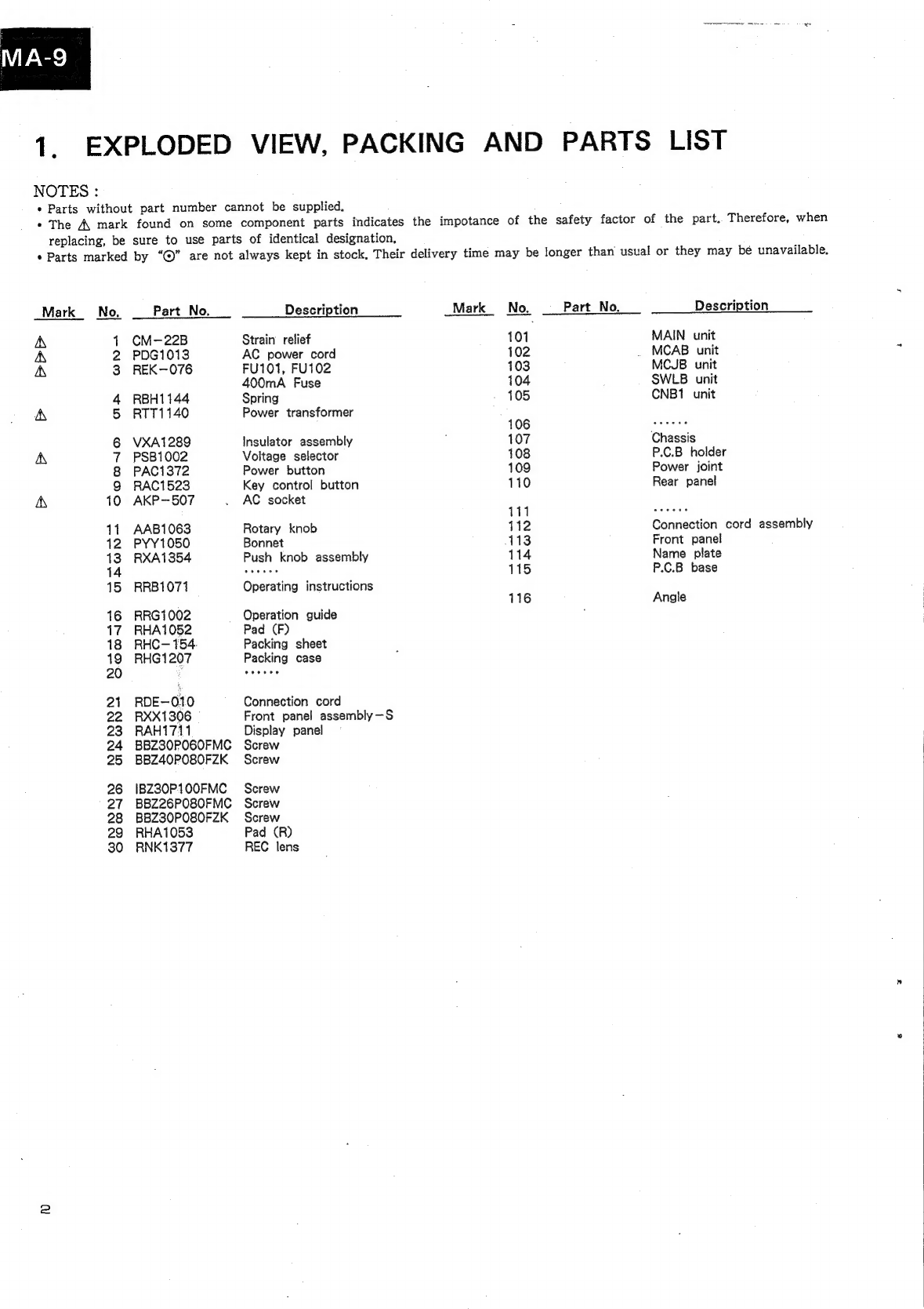
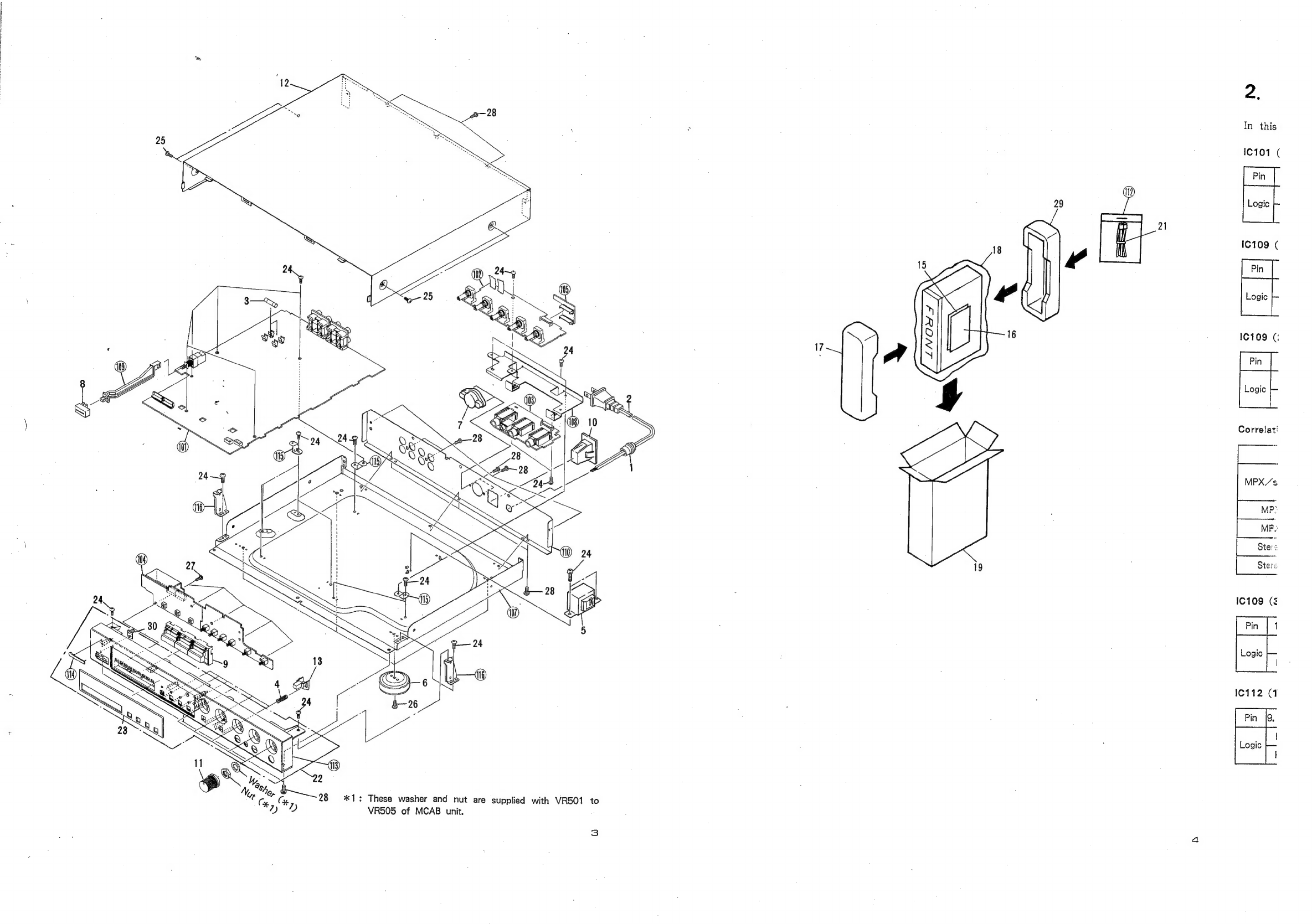
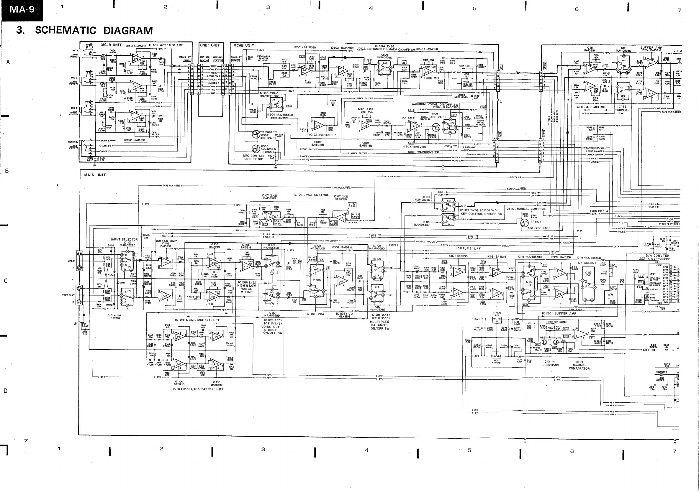
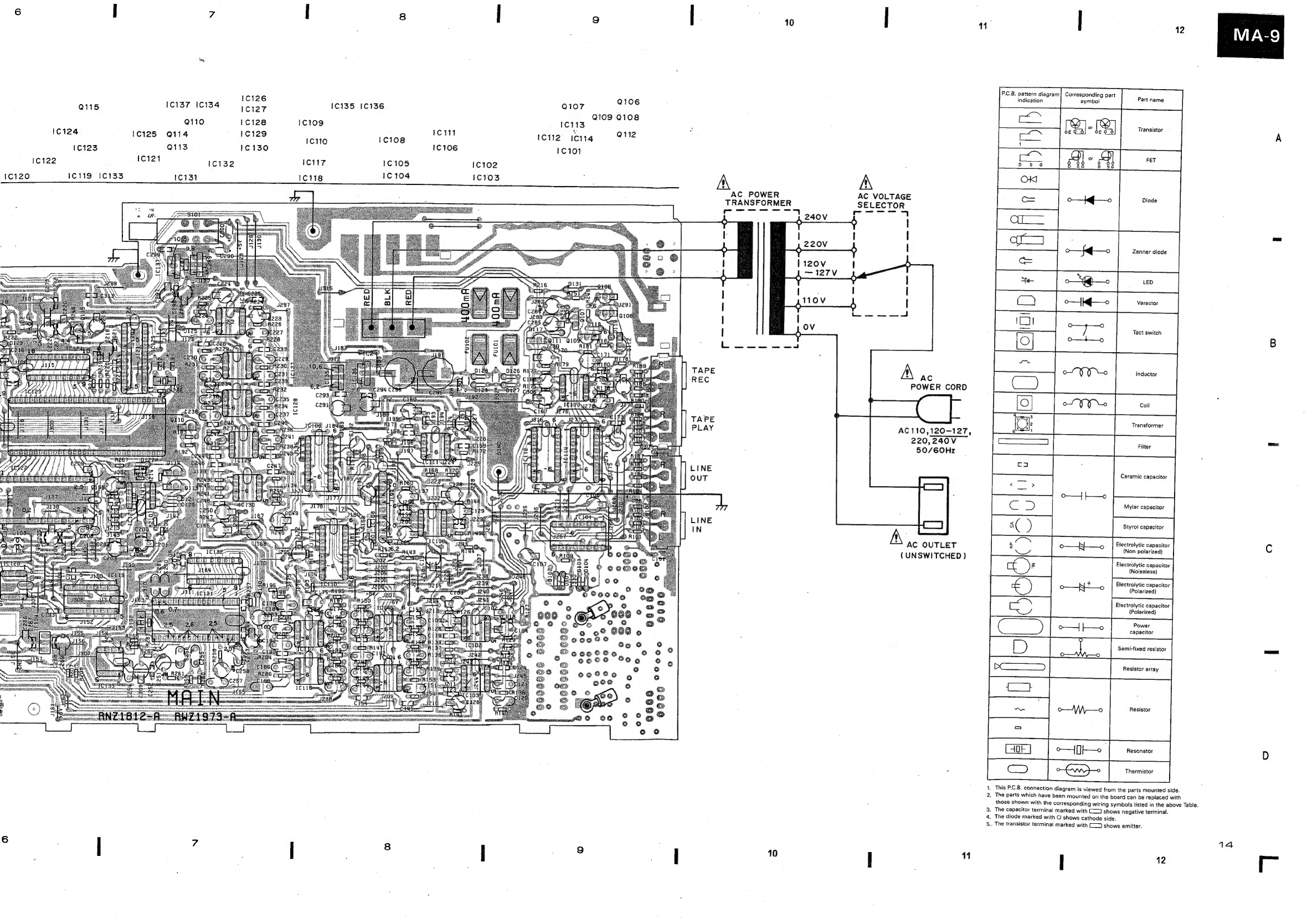
Pioneer MA-9 User manual
Other Pioneer Music Mixer manuals

Pioneer
Pioneer SVM 1000 - Audio/Video Mixer User manual

Pioneer
Pioneer DJM-600 User manual

Pioneer
Pioneer DJM-800 User manual

Pioneer
Pioneer DJD-707 User manual

Pioneer
Pioneer DJM-850-K User manual

Pioneer
Pioneer DJM-700-K User manual

Pioneer
Pioneer DJM 909 - Battle Mixer W/Effects User manual

Pioneer
Pioneer DJM-900NXS2 User manual

Pioneer
Pioneer DJM-707 User manual

Pioneer
Pioneer CDJ-2000 Setup guide

Pioneer
Pioneer DDJ-RB User manual

Pioneer
Pioneer DJM-S9 User manual

Pioneer
Pioneer DJM 5000 - Professional Standard Mobile DJ... User manual

Pioneer
Pioneer DJM-900SRT User manual

Pioneer
Pioneer DJM-T1 User manual

Pioneer
Pioneer DDJ-T1 User manual

Pioneer
Pioneer DJM-2000 User manual

Pioneer
Pioneer DJM-700 User manual

Pioneer
Pioneer DJM-T1 User manual

Pioneer
Pioneer DJM-900NXS2 User manual