Pioneer pdk-50hw2a User manual

HAND WRITING DEVICE
Dispositif d’écriture manuscrite
Beschriftungsgerät
PDK-50HW2A
Operating Instructions
Mode d’emploi
Bedienungsanleitung
ハンドライティングデバイス
据付工事について
本機は十分な技術・技能を有する専門業者が据え
付けを行うことを前提に販売されているもので
す。据え付け・取り付けは必ず工事専門業者また
は販売店にご依頼ください。
なお、据え付け・取り付けの不備、誤使用、改
造、天災などによる事故損傷については、弊社は
一切責任を負いません。

13
English
En
SAFETY PRECAUTIONS
Notes on Installation Work:
This product is marketed assuming that it is installed by qualified
personnel with enough skill and competence. Always have an
installation specialist or your dealer install and set up the product.
PIONEER cannot assume liabilities for damage caused by
mistake in installation or mounting, misuse, modification or a
natural disaster.

14
En
SAFETY PRECAUTIONS
[for US model]
IMPORTANT NOTICE
The serial number for this equipment is located on the bottom
of the frame. Please write this serial number on your enclosed
warranty card and keep it in a secure area. This is for your
security.
CAUTION: WHEN POSITIONING THIS EQUIPMENT
ENSURE THAT THE MAINS PLUG AND SOCKET IS EASILY
ACCESSIBLE.
To ensure proper heat radiation, distance the unit slightly from
other equipment, walls, etc. (normally more than 10 cm). Avoid
the following installations which will block vents and cause heat
to build up inside, resulting in fire hazards.
• Do not attempt to fit the unit inside narrow spaces where
ventilation is poor
• Do not place on carpet
• Do not cover with cloth, etc.
• Do not place on its side
• Do not place it upside down
• If planning special installation such as fitting close to the wall,
placing it horizontally, etc., be sure to consult your Pioneer
dealer first.
Operating Environment H045 En
Operating environment temperature and humidity:
0 °C – +40 °C (+32 °F – +104 °F); less than 85 %RH (cooling vents
not blocked)
Do not install in the following locations
÷Location exposed to direct sunlight or strong artificial light
÷Location exposed to high humidity, or poorly ventilated lo-
cation
WARNING:
Handling the cord on this product or cords associ-
ated with accessories sold with the product will ex-
pose you to lead, a chemical known to the State of
California and other governmental entities to cause
cancer and birth defects or other reproductive harm.
Wash hands after handling

15
English
En
SAFETY PRECAUTIONS
FEDERAL COMMUNICATIONS COMMISSION
DECLARATION OF CONFORMITY
This device complies with part 15 of the FCC Rules. Operation is subject to the following
two conditions: (1) This device may not cause harmful interference, and (2) this device
must accept any interference received, including interference that may cause undesired
operation.
Product Name: Hand Writing Device
Model Number: PDK-50HW2A
Product Category: Class B Personal Computers & Peripherals
Responsible Party Name: PIONEER ELECTRONICS (USA) INC. Customer Support Division
Address: P.O. BOX 1760, LONG BEACH, CA., 90801-1760 U.S.A.
Phone: (800)421-1625
For Business Customer URL http://www.PioneeUSA.com
Note for Dealers:
After installation, be sure to deliver this manual to the customer
and explain to the customer how to handle the product.
[for US model]

16
En
Thank you for buying this Pioneer product.
Please read through these operating instructions so you
will know how to operate your model properly. After you
have finished reading the instructions, put them away in a
safe place for future reference.
In some countries or regions, the shape of the power plug
and power outlet may sometimes differ from that shown in
the explanatory drawings. However the method of
connecting and operating the unit is the same. K015 En
FEATURES
The Handwriting Device allows the use of a special dedicated pen
for computer input operations on the screen of the plasma display.
Input and other operations can also be performed easily with your
finger.
7Uses infrared scanning technology to prevent screen quality
degradation.
7High-speed scanning technology provides high response with
high resolution equivalent to XGA standards.
<Contents>
FEATURE ............................................................................................................................ 16
ACCESSORIES ................................................................................................................... 17
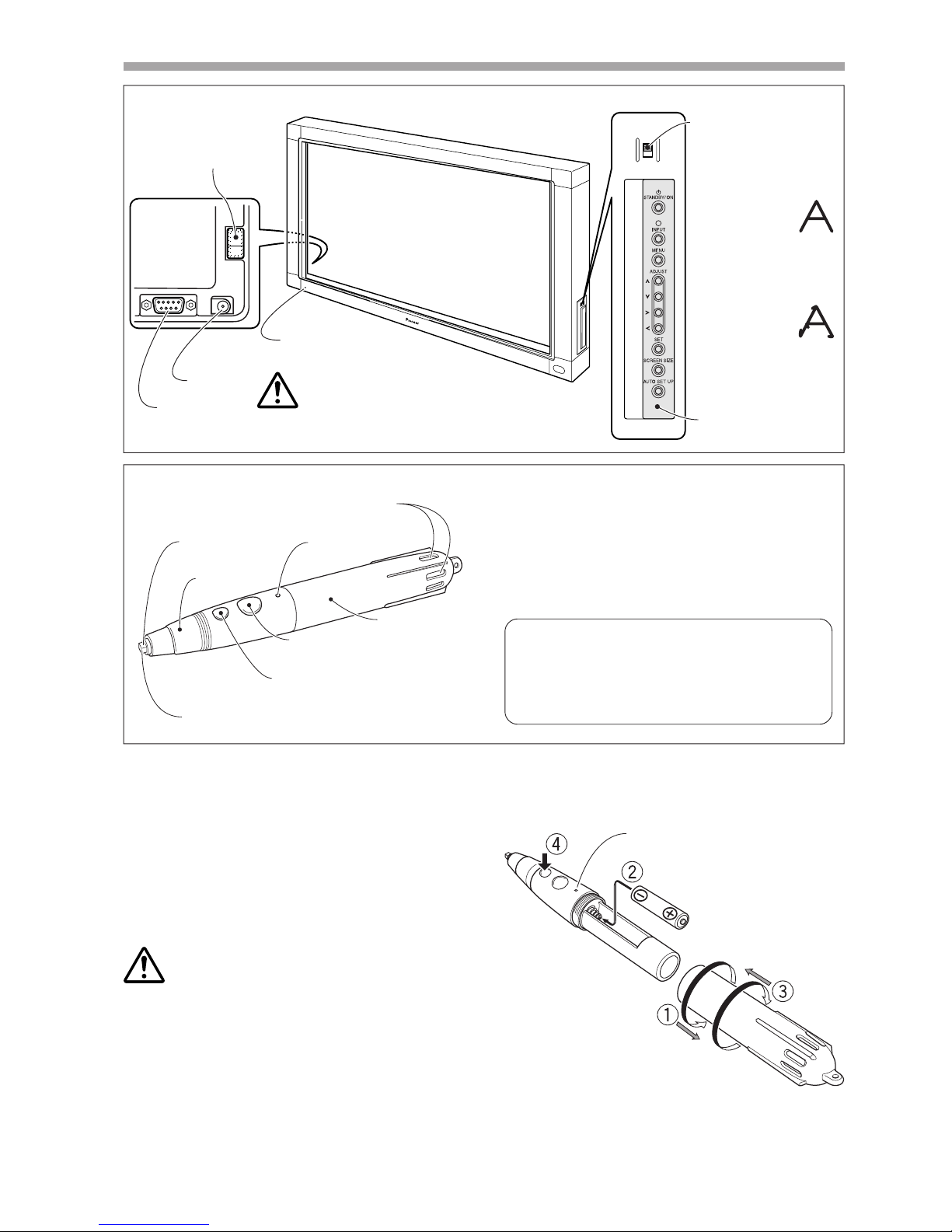
NAME AND FUNCTION OF PARTS ................................................................................... 18
Main Unit .......................................................................................................................18
Pen ................................................................................................................................. 18
Changing the Pen Battery ............................................................................................. 18
Replacing the Pen Tip .................................................................................................... 19
INSTALLATION ................................................................................................................... 19
Attach the Main Unit ..................................................................................................... 19
Attach the Pen Stand .................................................................................................... 19
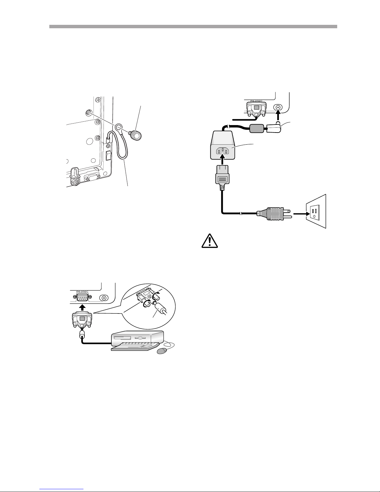
Connections ................................................................................................................... 20
Connect Ground Wire ............................................................................................... 20
Connecting the Plasma Display to a Computer ....................................................... 20
Connect the Unit to the Computer .......................................................................... 20
Connect the Power Cord .......................................................................................... 20
Software Installation ...................................................................................................... 20
Setting the Display Resolution ................................................................................. 20
Adjusting the Plasma Display ................................................................................... 21
Installing the Driver Software .................................................................................. 21
Alignment of Pen Tip and Cursor Position ............................................................... 21
TROUBLESHOOTING ......................................................................................................... 22
CLEANING .......................................................................................................................... 23
SPECIFICATIONS ............................................................................................................... 24
For details regarding operation of the Pioneer plasma
display, consult the Plasma Display Operating Instructions.
CAUTIONS REGARDING HANDLING
This unit has been designed for use only with Pioneer
Plasma Display models PDP-503CMX and PDP-503MXE.
It cannot be used with models PDP-502MX or PDP-
502MXE.

17
English
En
ACCESSORIES
Using this list, confirm that all accessories are present, and check them off one-by-one here ✔.
Pen (x1)
AAA (LR03) alkaline batteries (x2)
Replacement tips (x2)
Pen stand (x1)
RS-232C cable (9-pin, straight, 3m) (x1)
AC adapter (x1)
Power cord (x1)
Allen bolt (x2)
Operating Instructions (x1)
Driver software disc (x1)
Warranty Card (x1)

18
En
PEN
NORMAL
RS-232C DC IN
ON
OFF
Power indicator
(Lights green when ON)
Power switch
DC-IN jack
RS-232C
connector
Rear side
of unit
Plasma Display
Operation Panel
Mode selector switch
Set the mode switch in
accordance with whether
you will use the special
pen or other device to
input characters and lines
on the screen.
PEN Mode:
In this mode, the
special accessory
pen can be used to write
on the screen. Using the
special pen allows the
drawing of more clearly
delineated characters and
lines.
NORMAL Mode:
In this mode, your
finger or other
object can be used to write
on the screen. This mode
will produce lower screen
definition, however,
compared to drawing with
NAME AND FUNCTION OF PARTS
<Main Unit>
NOTE:
When the power switch is first turned on, the power
indicator will flash orange; while the indicator is flashing
(about 3 seconds), do not touch the screen, since the unit is
initializing its internal settings.
Tip
Cap
Pen tip
(corresponds to left mouse button)
LED indicator
Battery cover
Battery cover hole
Large button
(corresponds to right
mouse button)
Small button
(corresponds to middle
mouse button)
<Pen>
If pen operation becomes difficult:
The pen may fail to operate properly if the battery cover
holes are blocked. Also, the pen may begin operating
erratically when the battery becomes depleted. In this
event, change the battery at your earliest opportunity.
Confirming Battery Life:
When the small button is depressed fully, an LED
indicator will light. If the indicator fails to light, or
lights only dimly, the battery is depleted and should
be replaced.
<Changing the Pen Battery>
1Rotate the battery cover to the left (counterclockwise),
and pull off to remove.
2Insert a new AAA battery, aligning the +/– polarity
properly in accordance with the diagram (insert the "–"
end first against the spring, then slip the "+" side into the
tube slot).
3Replace the battery cover and rotate to the right
(clockwise) to tighten.
4Depress the small button fully to confirm that the LED
indicator lights.
NOTES:
÷To prevent damage from battery leakage, remove the
battery when not using the pen for an extended period
(1 month or more). If battery leakage occurs, wipe away
any battery fluid from inside the case and replace the
battery with a new one.
÷The provided alkaline battery should not be recharged,
short-circuited, disassembled, or disposed of in fire.
÷When disposing of used batteries, please comply with
governmental regulations or environmental public
instruction’s rules that apply in your country / area.
LED indicator
AAA (LR03) alkaline battery
Battery cover

19
English
En
2~3mm
NAME AND FUNCTION OF PARTS
<Replacing the Pen Tip>
The accessory pen tip is made of felt. If the tip becomes
deformed and writing quality deteriorates, replace the tip
with one of the supplied extras.
1. Pull out the felt tip.
CAUTION:
If you continue using a pen with a damaged or worn felt tip,
the monitor screen may be damaged.
2. Insert a new felt tip.
Press the felt tip into the pen so that about the tip is
exposed by about 2 –3 mm.
INSTALLATION
NOTES:
÷Always install the plasma display on a mobile cart before
installing this unit.
÷After installing this unit, never attempt to lift the plasma
display to install on a mobile cart.
÷When this unit is mounted to variable-angle Pioneer
Hung on Wall Unit PDK-5006 or PDK-5011, it cannot be
installed in a tilting position.
÷If the need arises to move the unit after it is installed on
a mobile cart, take care not to apply pressure on the unit
when moving. Always lift by the mobile cart when
moving.
1. Remove the "Pioneer" emblem from the
plasma display.
The emblem is affixed with two-sided tape (aligned with
two guide pins). Remove the emblem so that no tape
remains.
The unit will not operate
properly if the emblem is
not removed.
2. Place the unit over the front of the plasma dis-
play.
3.
Use the locking fixture on the rear panel to se-
cure the four corners of the unit.
1Rotate the locking fixture in the direction indicated by
the arrow (rotate in the opposite direction for the left-
side fixture), to secure the unit in place.
2Press in the locking fixture's stopper to prevent the
fixture from moving.
<Attach the Pen Stand>
7Use the furnished Allen bolt to fasten the pen
stand in place to the rear side of the unit.
Pen stand Allen bolt
<Attach the Main Unit>
÷Hold the pen stand upright and against the bottom of
the unit when inserting the Allen bolt.
Rear side of unit
Locking fixture
Stopper

20
En
DC IN
DC IN
INSTALLATION
<Connections>
Be sure to turn off the power switch and disconnect
the power cord from its outlet whenever making or
modifying connections.
Connect Ground Wire
Use the provided Allen bolt to connect the free end of the
unit's ground wire to the M8 hole in the rear panel of the
plasma display.
Rear side of unit
RS-232C cable
Computer
Connect the Power Cord
1. Connect the accessory AC adapter's DC plug to
the DC-IN jack of the unit.
2. Using the accessory power cord, connect the
AC adapter to an ordinary power outlet.
Rear side of unit
DC plug
AC Adapter
* The provided self-adhering fastener
tape provides a convenient means
of holding the AC adapter in place.
This fastener tape can also be used
when an extension cord or multiple
outlet power connector is used.
Power cord
CAUTION:
÷Always use the dedicated AC adapter and power cord
provided.
÷Do not use any voltage or power source other than that
designated, since fire or shock may result.
÷This unit is provided with a three-wire (grounded) cord to
help assure proper performance. Connect the power
cord to a power outlet equipped with a ground line, to
confirm that the cord is properly grounded. When using
a conversion plug, connect the plug's two blades to a
grounded outlet, with the plug's ground wire connected
to a proper ground screw.
<Software Installation>
Setting the Display Resolution
7In order to produce best performance, the video card
used must support 1280 x 768 resolution real display.
For details, consult your computer dealer or Pioneer.
7Set your computer's display resolution and refresh rate
to 1280 x 768 (60 Hz).
If any other display resolution is used, it will be
necessary to modify settings after installing the driver
software. For details, consult the README file
accompanying the driver software.
Ferrite core
Connecting the Plasma Display to a Computer
Consult the section "Installation and Connections" of the
plasma display's Operating Instructions for details on
connections to a computer.
Connect the Unit to the Computer
Using the accessory RS-232C cable, connect the unit's RS-
232C port to the computer. The accessory RS-232C cable
is provided with a ferrite core near one end. Connect that
end of the cable to the unit.
Knurled Allen bolt
Ground wire
M8

21
English
En
SELECT ENTER EXIT
SET
MENU
PICTURE SCREEN SET UP OPTION
:
NT
:AUTO
SETT I N
CLAMP
POWE R
:
G
OFF
PSITIONO
MNAGEMEA
INPUT INPUT
1
LEBLA
:XGA
MAIN MENU INPUT1
7Next, adjust the screen display to set the image
position and clock.
7Set the mask control and orbiter mode to OFF.
This setting should be made only by a factory trained
technicion or your dealer. If this function is set to ON,
the plasma display's display position will change,
causing a deviation between the pen tip and its
onscreen display position, and which cannot be rectified
by later calibration.
Installing the Driver Software
Consult the driver installation guide.
Alignment of Pen Tip and Cursor Position
Confirm that the onscreen cursor aligns properly with the
position of the pen tip.
Pen tip
Mouse cursor
(screen display
position)
If the cursor position differs from that of the physical pen
tip, adjust as follows:
1. Using your mouse, left-click on the CBdrv icon
in the task tray.
NOTE:
The actual appearance of your task tray may differ
depending on your computer configuration.
2. When the pop-up menu appears, left-click on
"Calibration."
INSTALLATION
3. Follow the calibration instructions that appear
onscreen.
NOTE:
Input to the unit can be performed with a finger or other
object in addition to the special dedicated pen; mechanical
pencils or other sharp objects should not be used,
however, since the screen may be scratched as a result.
When performing onscreen operations, the dedicated pen
or a fingertip should always be used.
Adjusting the Plasma Display
To properly adjust the plasma display, consult the section
"Setting Up the System" and "Display Panel Adjustments" in
the plasma display's operating instructions.
7First, set the System Settings.
Set screen display mode.
To use 1280 x 768 (60 Hz/70 Hz) screen resolution and
refresh rate, set the screen display mode to "WIDE
XGA."
With the screen image turned on, select MENU =SET
UP =SETTING =SET, and change the XGA setting to
WIDE XGA.

22
En
TROUBLESHOOTING
Incorrect operations are often mistaken for trouble and malfunctions. If you think there is something wrong with this
component, check the points below. Sometimes the trouble may originate from another component. Thus, also check the
other electrical appliances also in use.
If the trouble cannot be rectified even after checking the following items, contact your dealer or nearest PIONEER service center.
Symptom
No power
Computer doesn't boot properly, or
doesn't respond.
Cursor position is far from that of
pen tip on screen.
Cursor position diverges slightly
from that of pen tip on screen.
Cursor position diverges from pen
after initial setting.
The special dedicated pen does not
respond.
Cannot perform onscreen input with
objects other than special dedicated
pen.
The unit doesn't respond to writing,
or can't write in some areas of
screen.
Cause
÷The power plug is disconnected
from outlet.
÷Power cord is disconnected from
AC adapter.
÷AC adapter plug is disconnected
from DC-IN jack on the unit.
÷RS-232C cable is disconnected.
÷Wrong COM port is selected with
driver software.
÷Computer's serial port is not
functioning.
÷Driver software is not starting.
÷Computer is in power-saving mode.
÷A screen resolution other than
1280x768 is being used. Or
resolution has been changed.
÷The plasma display's screen display
size setting has been changed.
÷The plasma display's screen display
position has shifted.
÷The plasma display's AUTO SET UP
screen position adjustment has
been reset.
÷The plasma display's mask control
or orbiter mode have been set to
ON.
÷Battery is depleted.
÷Insufficient pen tip pressure is
being used so that the pen tip
switch doesn't turn on.
÷The pen's battery cover holes are
blocked.
÷The pen is being used outside of its
effective range.
÷The unit is receiving ultrasonic
influence from other device.
÷You are wearing gloves while
holding the pen (pen's ultrasonic
signals are being absorbed).
÷Mode selector switch on unit's side
is set to PEN.
÷Dust or dirt is adhering to infrared
transmission filter, thus blocking
infrared rays.
÷The Pioneer logo emblem is not
removed from plasma display.
Solution
÷Connect power plug to outlet correctly.
÷Connect power cord to AC adapter.
÷Connect the AC adapter's plug to the
DC-IN jack on the unit.
÷Connect RS-232 cable properly.
÷Set the driver software to the COM
port used with the unit.
÷Adjust your computer as necessary to
enable the serial port.
÷Install and enable the driver software.
÷Restore computer from power-saving
mode.
÷If necessary, modify computer's
power-saving setting.
÷Change the driver software settings as
required.
÷Use the plasma display's calibration
mode to adjust the vertical and
horizontal position.
÷Depending on the image, slight
divergences can be manually corrected.
÷Settings of the plasma display's mask
control and orbiter mode should be
made only by a factory trained
technician or your dealer.
÷Check the LED indicator, and if it does
not light brightly, replace battery.
÷Press the felt tip to the screen with
sufficient pressure to turn on the pen
tip switch.
÷Do not cover the battery cover holes.
÷Use only within the proper onscreen
usage range.
÷Do not place any device near the unit
that issues ultrasonic waves.
÷Remove gloves.
÷Set switch to NORMAL.
÷Clean dirt from the unit, turn off power
switch temporarily then turn on again.
÷Remove Pioneer emblem.

23
English
En
TROUBLESHOOTING
CAUTION:
÷If two or more units are operated closely together in PEN
mode, mutual interference may occur, resulting in
malfunction. If two or more units are to be used closely
together, set them all to NORMAL mode.
÷Due to the characteristics of its scanning mode, this product
cannot be used simultaneously by two different people. If
more than one person is to operate the unit, each person
should use it separately, one person at a time. Also,
malfunction may occur if the screen is touched during input
by another hand or object besides the pen tip or fingertip
(clothes or necktie, etc.). For this reason, do not touch the
screen with objects other than the actual tip of the input
instrument (fingertip or pen tip).
÷The pen may malfunction or input may be disrupted if the
pen is held at an excessively sharp angle to the screen. So
far as possible, hold the pen perpendicularly to the screen
during use.
CLEANING
In order to promote long life and optimum performance, regular
cleaning is recommended. Wipe the screen surface and pen tip
gently with a soft cloth to prevent dust buildup. In the case of
severe soiling, dip a soft cloth in a mild solution of a neutral
detergent, wring well, and wipe the screen surface gently, then
follow with a dry, soft cloth.
CAUTION:
÷Always disconnect power plug from its outlet before
performing cleaning.
÷Never use benzene, thinners or other volatile chemicals to
clean the unit, since deformation or discoloration of the unit
and pen may occur.

24
En
SPECIFICATIONS
Scanning system .................................... Infrared scanning
Input connectors ............................... DC-IN jack (6 V, 1 A)
Communication connector (RS-232C) ............. 9-pin D-sub
Power switch ................................................. Rocker type
Power indicator ........................................................... LED
Power ..................................................................... DC 6 V
Power consumption (DC 6 V) ....................................... 1 A
External dimensions
(including plasma display, excluding pen stand)
............................ 1,258 (W) x 758 (H) x 113 (D) mm
Weight (excluding plasma display and pen stand) ... 5.9 kg
AC Adapter
Input voltage ............................................... AC 100–240 V
Input frequency ................................................... 50/60 Hz
Dedicated Pen
Transmission ............................................ Ultrasonic wave
Operation switches ........................ Pen tip (x1), Body (x2)
Power ............................... AAA (LR03) alkaline battery x 1
External dimensions .......................... 27 (W) x 182 (L) mm
Weight (including battery) .......................................... 55 g
Accessories
Pen ............................................................................... 1
AAA (LR03) alkaline batteries .......................................... 2
Replacement pen tips ..................................................... 2
Allen bolt ......................................................................... 2
Pen stand ........................................................................ 1
RS-232C cable (3 m) ........................................................ 1
AC adapter ...................................................................... 1
Power cord ...................................................................... 1
Operating Instructions..................................................... 1
Warranty card .................................................................. 1
Driver software disc ........................................................ 1
÷Specifications and appearance may change without notice.
<Dimensional Diagram>
93
80
Unit: mm
(including bolt head)
(including plasma display)
(Average connector protrusion)
113
70
60
758
48
224220
1258
Published by Pioneer Corporation.
Copyright © 2002 Pioneer Corporation.
All rights reserved.

25
Français
Fr
Remarques sur l’installation:
Ce produit est vendu en assumant qu’il sera installé par un
personnel suffisamment expérimenté et qualifié. Faites toujours
réaliser le montage et l’installation par un spécialiste ou par votre
revendeur.
PIONEER ne peut être tenu responsable pour tout dommage
causé par une erreur d’installation ou de montage, une mauvaise
utilisation ou un désastre naturel.
Remarque pour le revendeur:
Après l’installation, assurez-vous de remettre ce mode d’emploi
à l’utilisateur et de lui expliquer comme utiliser ce produit.
AVERTISSEMENT: EN POSITIONNANT
L’EQUIPEMENT, S’ASSURER QUE LA FICHE ET LA PRISE DE
RACCORDEMENT DE L’ALIMENTATION SONT FACILEMENT
ACCESSIBLES.
Pour garantir un rayonnement thermique adéquat, placer l’unité
à une certaine distance des autres équipements, murs, etc.
(normalement à une distance supérieure à 10 cm). Eviter les
modes d’installation décrits ciaprès qui entraînent l’obstruction
des orifices et provoquent une accumulation de chaleur interne,
d’où un risque d’incendie.
• Ne pas essayer de placer l’unité dans des espaces réduirts et
mal ventilés
• Ne pas la placer sur un tapis
• Ne pas la recouvrir d’un tissu etc.
• Ne pas la placer sur le côté
• Ne pas la renverser
• Si une installation spéciale est envisagée, comme un montage
à proximité immédiate du mur, un placement horizontal,
consulter d’abord le revendeur Pioneer de votre région.
Conditions de Fonctionnement H045 Fr
Tempéraure et humidité ambiante lors du fonctionnement:
0 °C – +40 °C (+32 °F – +104 °F); inférieur à 85 %RH (events
d’aération non obstrués)
Ne pas installer dans les lieux suivants
÷Lieux exposés à la lumière direct du soleil ou lumière
artificielle forte
÷Lieux exposés à une forte humidité ou lieux peu ventilés
PRÉCAUTIONS DE SÉCURITÉ

26
Fr
Nous vous remercions pour cet achat d’un produit Pioneer.
Nous vous demandons de lire soigneusement ce mode
d’emploi; vous serez ainsi àmême de faire fonctionner
l’appareil correctement. Après avoir bien lu le mode
d’emploi, le ranger dans un endroit sûr pour pouvoir s’y
référer ultérieurement.
Dans certains pays ou certaines régions, la forme de la
fiche d’alimentation et de la prise d’alimentation peut
différer de celle qui figure sur les schémas, mais les
branchements et le fonctionnement de l’appareil restent
les mêmes. K015 Fr
CARACTÉRISTIQUES
Le Dispositif d’écriture manuscrite permet d’effectuer des
opérations de saisie informatique sur l’écran àplasma au moyen
d’un crayon spécialement conçu. La saisie et d’autres opérations
peuvent même être réalisées facilement avec le doigt.
7Utilisation d’une technologie de balayage àinfrarouge pour
éviter une dégradation de la qualitésur l’écran.
7Technologie de balayage àgrande vitesse, assurant une
réponse élevée et une haute résolution, équivalentes aux
normes XGA.
<Table des Matieres>
CARACTÉRISTIQUES ......................................................................................................... 26
ACCESSOIRES ................................................................................................................... 27
NOMENCLATURE ET FONCTIONS DES PIÈCES .............................................................. 28
Unitéprincipale .............................................................................................................. 28
Crayon ............................................................................................................................ 28
Changement de la pile du crayon .................................................................................. 28
Remplacement de la pile du crayon .............................................................................. 29
INSTALLATION ................................................................................................................... 29
Mise en place de l’unitéprincipale ................................................................................ 29
Fixation du porte-crayon ................................................................................................ 29
Branchements ............................................................................................................... 30
Branchement du fil de masse .................................................................................. 30
Branchement de l’écran àplasma àun ordinateur .................................................. 30
Branchement de l’unitésur un ordinateur ............................................................... 30
Branchement du cordon d’alimentation ................................................................... 30
Installation du logiciel .................................................................................................... 30
Réglage de la résolution d’affichage ........................................................................ 30
Ajustement de l’écran àplasma ............................................................................... 31
Installation du logiciel de pilotage ............................................................................ 31
Alignement de la mine du crayon et de la position du curseur ............................... 31
GUIDE DE DÉPANNAGE .................................................................................................... 32
NETTOYAGE .......................................................................................................................33
FICHE TECHNIQUE ............................................................................................................ 34
Pour les détails sur l’utilisation de l’écran àplasma de
Pioneer, veuillez consulter le Mode d’emploi de l’écran à
plasma.
AVERTISSEMENTS CONCERNANT L’USAGE
Cette unitéest conçue pour une utilisation avec les
modèles d'Écran àplasma Pioneer PDP-503CMX et PDP-
503MXE. Elle ne peut pas servir avec les modèles PDP-
502MX ou PDP-502MXE.

27
Français
Fr
ACCESSOIRES
Sur cette liste, cochez chacun des carrés ✔après vous être assuréque l’accessoire illustréest présent.
Crayon (x1)
Pile alcaline AAA (LR03) (x2)
Mine de rechange (x2)
Porte-crayon (x1)
Câble RS-232C (9 broches, droit, 3 m) (x1)
Adaptateur secteur (x1)
Cordon d’alimentation (x1)
Boulon à6 pans (x2)
Mode d’emploi (x1)
Disque de logiciel de pilotage (x1)
Carte de garantie (x1)

28
Fr
PEN
NORMAL
RS-232C DC IN
ON
OFF
Voyant d’alimentation
(Alluméen vert: Écran sous tension)
Interrupteur
d’alimentation
Prise DC-IN
Connecteur
RS-232C
Face arrière
de l’unité
Panneau d’exploitation
de l’écran àplasma
Sélecteur de mode
Réglez ce sélecteur selon que
vous voulez utiliser le crayon
spécial ou un autre instrument
pour la saisie de caractères et
de lignes sur l’écran.
Mode PEN:
Àcette position, ous
pouvez utiliser le crayon
spécial, fourni comme
accessoire, pour écrire sur
l’écran. L’emploi du crayon
spécial permet le tracéde
caractères et de lignes plus
clairement définies.
Mode NORMAL:
Àcette position, vous
pouvez utiliser le doigt
ou un autre objet pour
écrire sur l’écran. Notez que la
définition des tracés sur l’écran
sera moindre qu’avec le crayon
spécial de saisie.
NOMENCLATURE ET FONCTIONS DES PIÈCES
< Unitéprincipale >
REMARQUE:
Lors de la première mise sous tension, le voyant
d’alimentation clignote en orange. Pendant ce
clignotement (environ 3 secondes), ne touchez pas
l’écran car l’unitéeffectue alors l’initialisation de
ses réglages internes.)
Mine
Capuchon
Mine du crayon
(correspond au bouton gauche de souris)
Voyant LED
Couvercle
de pile
Orifices du couvercle de pile
Grand bouton
(correspond au bouton
droit de souris)
Petit bouton
(correspond au bouton
central de souris)
< Crayon >
Si l’utilisation du crayon devient difficile:
Le crayon risque de ne pas fonctionner correctement si
les orifices du couvercle de la pile sont obstrués. Il peut
aussi commencer àfonctionner de façon bizarre lorsque
la pile est presque épuisée. Dans ce cas, remplacez la
pile dans les meilleurs délais.
Vérification de la charge de la pile:
Lorsque le petit bouton est actionnéàfond, le voyant
LED s’allume. S’il ne s’allume pas ou si sa clartéest
faible, c’est que la pile est épuisée. Remplacez-la.
< Changement de la pile du crayon >
1Tournez le couvercle de pile vers la gauche (sens anti-
horaire) et tirez pour le déposer.
2Insérez une nouvelle pile AAA, en alignant ses polarités
+/–comme sur le schéma. Insérez le pôle “–” d’abord
contre le ressort, puis glissez le pôle “+”dans la fente
du tube.
3Replacez le couvercle de pile et tournez-le vers la droite
(sens horaire) pour le serrer.
4Appuyez sur le petit bouton pour vérifier que le voyant
LED s’allume.
REMARQUES:
÷Pour éviter des dégâts que causerait un suintement
d’électrolyte de la pile, retirez celle-ci si le crayon ne sera
pas utilisépendant une durée prolongée (un mois ou
plus). Si une fuite de la pile s’est produite, essuyez
convenablement l’électrolyte àl’intérieur du boîtier et
remplacez la pile par une neuve.
÷La pile alcaline fournie ne peut pas être rechargée,
court-circuitée, démontée ou jetée dans un feu.
÷Lorsque vous diposez de piles / batteries usées, veuillez
vous conformer aux normes gouvernementales ou
environnementales en vigueur dans votre pays ou
région.
Voyant LED
Pile alcaline AAA (LR03)
Couvercle de pile

29
Français
Fr
2~3mm
NOMENCLATURE ET FONCTIONS DES PIÈCES
<Remplacement de la pile du crayon>
La mine du crayon fourni comme accessoire est fabriquée
en feutre. Si le bout se déforme ou si la qualitéde l’écriture
diminue, remplacez la mine par une, fournies comme
accessoires.
1. Extrayez la mine en feutre.
ATTENTION:
Vous risquez d’abîmer l’écran si vous continuez d’utiliser une
mine de crayon usée ou endommagée.
2. Insérez une nouvelle mine.
Poussez la mine de feutre dans l’orifice de sorte qu’elle
ne dépasse que de 2 à3 mm environ.
INSTALLATION
REMARQUES:
÷Installez toujours l’écran àplasma sur un support mobile
avant de placer cette unité.
÷Après avoir installécette unité, n’essayez jamais de lever
l’écran àplasma pour le placer sur le support mobile.
÷Lorsque cette unitéest montée sur l’Écran Mural à
angle variable PDK-5006 ou PDK-5011 de Pioneer, elle
ne peut pas être installée en position inclinée.
÷S’il est nécessaire de déplacer l’unitéaprès l’avoir
installée sur le support mobile, veillez àne pas presser
sur l’unitépendant le déplacement. Soulevez-la toujours
par le support mobile pour la déplacer.
1. Retirez l’écusson “Pioneer”de l’écran à
plasma.
L’écusson est fixépar une bande biface (alignée avec
deux goujons de guidage). Déposez l’écusson sans
laisser de trace de la bande.
L’uniténe fonctionnera
pas correctement si
l’écusson n’est pas enlevé.
2. Placez l’unitésur l’avant de l’écran àplasma.
3.
Utilisez l'applique de fixation sur la face arrière
pour immobiliser les quatre coins de l'appareil.
1Tournez l'applique de fixation dans le sens indiqué
par la flèche (tournez dans le sens opposépour
l'applique du côtégauche) pour immobiliser l'unité.
2Enfoncez la butée de l'applique de fixation pour
empêcher tout mouvement de l'applique.
<Fixation du porte-crayon>
7Servez-vous du boulon à6 pans fourni pour
fixer le porte-crayon sur la face arrière de
l’unité.
Porte-crayon Boulon à6 pans
<Mise en place de l’unitéprincipale>
÷Tenez le porte-crayon d'équerre et contre le fond de
l'unitélorsque vous insérez le boulon.
Face arrière de l’unité
Applique de fixation
Butée

30
Fr
DC IN
DC IN
INSTALLATION
<Branchements>
Veillez àcouper l’alimentation et àdébrancher le
cordon d’alimentation au niveau de la prise secteur
chaque fois que vous effectuez ou modifiez les
branchements.
Branchement du fil de masse
Utilisez le boulon à6 pans fourni pour raccorder le bout
libre du fil de masse de l'appareil sur l'orifice M8 sur la face
arrière de l'écran àplasma.
Face arrière de l’unité
Câble RS-232C
Ordinateur
Branchement du cordon d’alimentation
1. Branchez la fiche DC de l’adaptateur secteur
sur la prise DC-IN de l’unité.
2. Au moyen du cordon d’alimentation fourni,
raccordez l’adaptateur secteur àune prise
secteur ordinaire.
Face arrière de l’unité
Fiche DC
Adaptateur secteur
* La bande auto-adhésive fournie
constitue un bon moyen pour fixer
l’adaptateur secteur. Cette bande
peut également servir si vous
utilisez un cordon-rallonge ou un
connecteur àmultiples prises
secteur.
Cordon d’alimentation
ATTENTION:
÷Utilisez uniquement l’adaptateur secteur spécial et le
cordon d’alimentation fourni.
÷Sous peine de provoquer un incendie ou une décharge
électrique, n’utilisez pas de tension ou de sources de
courant, autres que celles qui sont spécifiées.
÷Cette unités’accompagne d’un cordon àtrois fils (terre)
pour garantir la sécuritéde son fonctionnement.
Branchez le cordon d’alimentation dans une prise
secteur àfil de terre, de sorte qu’il soit correctement
mis àla masse. Si vous utilisez une fiche de conversion,
branchez les deux lames de la fiche sur une prise, mise
àla terre, et reliez le fil de terre de la fiche sur une vie de
terre appropriée.
<Installation du logiciel>
Réglage de la résolution d’affichage
7Pour obtenir d’excellents résultats, la carte vidéo utilisée
doit supporter un écran àrésolution de 1280 x 768. Pour
plus de détails, consultez Pioneer ou le concessionnaire
de votre ordinateur.
7
Réglez la résolution d’affichage et le taux de
rafraîchissement de votre ordinateur sur 1280 x 768 (60 Hz).
Si vous utilisez une autre résolution d’affichage, il sera
nécessaire de modifier les réglages après avoir installéle
logiciel pilote de périphérique. Pour des détails, consultez le
ficher README (Lisez-moi) qui accompagne le logiciel de
pilotage.
Ame de ferrite
Branchement de l’écran àplasma àun ordinateur
Reportez-vous au chapitre “Installation et branchements”
du Mode d’emploi de l’écran àplasma pour des détails sur
le raccordement àun ordinateur.
Branchement de l’unitésur un ordinateur
Au moyen du câble RS-232C fourni comme accessoire,
raccordez le port RS-232C de l’unitéàl’ordinateur. Le câble
RS-232C fourni comme accessoire est muni d'une âme en
ferrite àune de ses extrémités. Branchez cette extrémité
sur l'unité.
Fil de masse
Boulon moletéà6 pans
M8

31
Français
Fr
SELECT ENTER EXIT
SET
MENU
PICTURE SCREEN SET UP OPTION
:
NT
:AUTO
SETT I N
CLAMP
POWE R
:
G
OFF
PSITIONO
MNAGEMEA
INPUT INPUT
1
LEBLA
:XGA
MAIN MENU INPUT1
7Ajustez ensuite l’affichage sur écran pour ajuster la
position de l’image et l’horloge.
7Réglez le contrôle de masque et le mode orbiteur
sur OFF.
Ce réglage doit être effectuéuniquement par un
technicien spécialement forméou votre concessionnaire.
Si cette fonction est mise en service (ON), la position
d’affichage sur l’écran àplasma changera, entraînant un
décalage entre la mine du crayon et sa position
d’affichage sur l’écran. Ce décalage ne pourra pas être
corrigépar une calibration ultérieure.
Installation du logiciel de pilotage
Consultez le guide d’installation du logiciel pilote.
Alignement de la mine du crayon et de la position
du curseur
Vérifiez que le curseur sur l’écran correspond exactement
àla position de la mine du crayon.
Mine du
crayon
Curseur de
souris (position
d’affichage sur
écran)
Si la position du curseur diffère de celle de la mine réelle du
crayon, ajustez en procédant comme suit:
1. En vous servant de la souris, cliquez du bouton
gauche sur l’icône CBdrv dans le tiroir Tâches.
REMARQUE:
L’aspect réel de votre tiroir Tâches peut être différent selon
la configuration de votre ordinateur.
2. Lorsque le menu déroulant apparaît, cliquez du
bouton gauche sur “Calibration”.
INSTALLATION
3.
Suivez les instructions de calibrage, apparaissant
sur l’écran.
REMARQUE:
Outre le crayon spécialement conçu, le doigt ou un autre
objet peut être utilisépour la saisie sur le Dispositif
d’écriture manuscrite. Toutefois, n’utilisez pas de stylet
métallique ou un objet pointu car l’écran pourrait en être
griffé. Utilisez uniquement le crayon spécial ou le bout du
doigt pour effectuer des opérations sur l’écran.
Ajustement de l’écran àplasma
Pour ajuster correctement l’écran àplasma, consultez les
chapitres “Configuration du Système”et “Ajustements du
panneau d’affichage”dans le mode d’emploi de l’écran à
plasma.
7Effectuez d’abord les réglages du système.
Réglez le mode d’affichage sur écran.
Pour utiliser la résolution d’écran et le taux de
rafraîchissement de 1280 x 768 (50 Hz/70 Hz), réglez le
mode d’affichage sur écran à“WIDE XGA”,
L’écran étant sous tension, sélectionnez MENU =SET
UP =SETTING =SET et changez le réglage XGA en
WIDE XGA.
Table of contents
Languages:
Other Pioneer Touch Panel manuals
Popular Touch Panel manuals by other brands

Tyco Electronics
Tyco Electronics ET2639L user guide

Alula
Alula RE667W manual

Bender
Bender MK2000 reference guide

C&T
C&T WIO-W221C Series user manual

Endress+Hauser
Endress+Hauser ControlCare SPC150 operating instructions

Beijer Electronics
Beijer Electronics X2 marine 7-B2 SC Hardware and installation manual