Pioneer V050-PPI-01 User manual

pioneerpump.com
ENGLISHEN
ElectricPAK VFD with SmartPrime
Owner’s Manual

2
TABLE OF CONTENTS
PRODUCT INFORMATION - - - - - - - - - - - - - - - - - - - - - - - - - - - - - - - - - - - - - - - - - - - - - - - - - - - - 5
Description- - - - - - - - - - - - - - - - - - - - - - - - - - - - - - - - - - - - - - - - - - - - - - - - - - - - - - - - - 5
Specifications - - - - - - - - - - - - - - - - - - - - - - - - - - - - - - - - - - - - - - - - - - - - - - - - - - - - - - - 5
UNPACKING & INSPECTION - - - - - - - - - - - - - - - - - - - - - - - - - - - - - - - - - - - - - - - - - - - - - - - - - - - 6
Transportation and Storage - - - - - - - - - - - - - - - - - - - - - - - - - - - - - - - - - - - - - - - - - - - - - - - - - 6
Unpacking - - - - - - - - - - - - - - - - - - - - - - - - - - - - - - - - - - - - - - - - - - - - - - - - - - - - - - - - - 6
Lifting - - - - - - - - - - - - - - - - - - - - - - - - - - - - - - - - - - - - - - - - - - - - - - - - - - - - - - - - - - - 6
INSTALLATION - - - - - - - - - - - - - - - - - - - - - - - - - - - - - - - - - - - - - - - - - - - - - - - - - - - - - - - - - 7
Environmental Requirements - - - - - - - - - - - - - - - - - - - - - - - - - - - - - - - - - - - - - - - - - - - - - - - - 7
Special Considerations for Outdoor Use - - - - - - - - - - - - - - - - - - - - - - - - - - - - - - - - - - - - - - - - - 7
Physical Installation- - - - - - - - - - - - - - - - - - - - - - - - - - - - - - - - - - - - - - - - - - - - - - - - - - - - - 8
Electrical Installation - - - - - - - - - - - - - - - - - - - - - - - - - - - - - - - - - - - - - - - - - - - - - - - - - - - - 9
Wiring Instructions - - - - - - - - - - - - - - - - - - - - - - - - - - - - - - - - - - - - - - - - - - - - - - - - - - - 9
Motor Rotation- - - - - - - - - - - - - - - - - - - - - - - - - - - - - - - - - - - - - - - - - - - - - - - - - - - - - 10
DRIVE CONFIGURATION- - - - - - - - - - - - - - - - - - - - - - - - - - - - - - - - - - - - - - - - - - - - - - - - - - - - - 11
Home Screen Navigation - - - - - - - - - - - - - - - - - - - - - - - - - - - - - - - - - - - - - - - - - - - - - - - - - - 11
Changing Date & Time - - - - - - - - - - - - - - - - - - - - - - - - - - - - - - - - - - - - - - - - - - - - - - - - - - - 12
Setting Operating Parameters- - - - - - - - - - - - - - - - - - - - - - - - - - - - - - - - - - - - - - - - - - - - - - - - 13
Motor Configuration - - - - - - - - - - - - - - - - - - - - - - - - - - - - - - - - - - - - - - - - - - - - - - - - - - 13
ElectricPAK™ Motor Setup - - - - - - - - - - - - - - - - - - - - - - - - - - - - - - - - - - - - - - - - - - - - - 13
Non-ElectricPAK™ Motor Setup- - - - - - - - - - - - - - - - - - - - - - - - - - - - - - - - - - - - - - - - - - - 14
Sensor Setup- - - - - - - - - - - - - - - - - - - - - - - - - - - - - - - - - - - - - - - - - - - - - - - - - - - - - - 15
Auto Mode Settings Screen Navigation - - - - - - - - - - - - - - - - - - - - - - - - - - - - - - - - - - - - - - - - - - - 16
Float Control Configuration - - - - - - - - - - - - - - - - - - - - - - - - - - - - - - - - - - - - - - - - - - - - - - - - - 17
Float Setup - - - - - - - - - - - - - - - - - - - - - - - - - - - - - - - - - - - - - - - - - - - - - - - - - - - - - - 17
Auto Mode Float Configuration - - - - - - - - - - - - - - - - - - - - - - - - - - - - - - - - - - - - - - - - - - - - - 17
Transducer Application Setup - - - - - - - - - - - - - - - - - - - - - - - - - - - - - - - - - - - - - - - - - - - - - - - - 17
Level Transducer Control Configuration - - - - - - - - - - - - - - - - - - - - - - - - - - - - - - - - - - - - - - - - - 18
Auto Mode without Backup Float Configuration- - - - - - - - - - - - - - - - - - - - - - - - - - - - - - - - - - - 18
Auto Mode with a Backup Float Configuration - - - - - - - - - - - - - - - - - - - - - - - - - - - - - - - - - - - 18
Discharge Pressure Transducer Configuration - - - - - - - - - - - - - - - - - - - - - - - - - - - - - - - - - - - - - - 19
Advanced Settings - - - - - - - - - - - - - - - - - - - - - - - - - - - - - - - - - - - - - - - - - - - - - - - - - - - - - 19
Changing Advanced Settings Password - - - - - - - - - - - - - - - - - - - - - - - - - - - - - - - - - - - - - - - - -20
OPERATION- - - - - - - - - - - - - - - - - - - - - - - - - - - - - - - - - - - - - - - - - - - - - - - - - - - - - - - - - - - 21
Manual Mode - - - - - - - - - - - - - - - - - - - - - - - - - - - - - - - - - - - - - - - - - - - - - - - - - - - - - - - - 21
Manual Mode Screen Navigation - - - - - - - - - - - - - - - - - - - - - - - - - - - - - - - - - - - - - - - - - - - - 21
Manual Control Buttons - - - - - - - - - - - - - - - - - - - - - - - - - - - - - - - - - - - - - - - - - - - - - - 22
Speed Control Source - - - - - - - - - - - - - - - - - - - - - - - - - - - - - - - - - - - - - - - - - - - - - - - 22
Manually Starting the Package - - - - - - - - - - - - - - - - - - - - - - - - - - - - - - - - - - - - - - - - - - - - - 23
Auto Mode - - - - - - - - - - - - - - - - - - - - - - - - - - - - - - - - - - - - - - - - - - - - - - - - - - - - - - - - - 24
Basic Auto Mode Screen Navigation- - - - - - - - - - - - - - - - - - - - - - - - - - - - - - - - - - - - - - - - - - -24
Float Control Application Startup - - - - - - - - - - - - - - - - - - - - - - - - - - - - - - - - - - - - - - - - - - - - 25
Level Transducer Control Startup - - - - - - - - - - - - - - - - - - - - - - - - - - - - - - - - - - - - - - - - - - - -26
Backup Float Fault- - - - - - - - - - - - - - - - - - - - - - - - - - - - - - - - - - - - - - - - - - - - - - - - - 27
Discharge Pressure Transducer Control Startup - - - - - - - - - - - - - - - - - - - - - - - - - - - - - - - - - - - - - 27
Hand Mode Operation - - - - - - - - - - - - - - - - - - - - - - - - - - - - - - - - - - - - - - - - - - - - - - - - - - - 28
Sensor Status Screen - - - - - - - - - - - - - - - - - - - - - - - - - - - - - - - - - - - - - - - - - - - - - - - - - - - - 29
Data Logs - - - - - - - - - - - - - - - - - - - - - - - - - - - - - - - - - - - - - - - - - - - - - - - - - - - - - - - - - 30

3
Alarms Screen - - - - - - - - - - - - - - - - - - - - - - - - - - - - - - - - - - - - - - - - - - - - - - - - - - - - - - - 31
Help Screen - - - - - - - - - - - - - - - - - - - - - - - - - - - - - - - - - - - - - - - - - - - - - - - - - - - - - - - - 31
MAINTENANCE- - - - - - - - - - - - - - - - - - - - - - - - - - - - - - - - - - - - - - - - - - - - - - - - - - - - - - - - - 32
Periodic Maintenance - - - - - - - - - - - - - - - - - - - - - - - - - - - - - - - - - - - - - - - - - - - - - - - - - - - 32
Air Filter Replacement - - - - - - - - - - - - - - - - - - - - - - - - - - - - - - - - - - - - - - - - - - - - - - - - - 32
SD Card Data & Alarm Log Download- - - - - - - - - - - - - - - - - - - - - - - - - - - - - - - - - - - - - - - - - - 33
SD Card Re-installation - - - - - - - - - - - - - - - - - - - - - - - - - - - - - - - - - - - - - - - - - - - - - - 33
Troubleshooting - - - - - - - - - - - - - - - - - - - - - - - - - - - - - - - - - - - - - - - - - - - - - - - - - - - - - - 34
ADVANCED SETTINGS REFERENCE - - - - - - - - - - - - - - - - - - - - - - - - - - - - - - - - - - - - - - - - - - - - - - - 35

SAFETY INSTRUCTIONS
4
SAFETY INSTRUCTIONS
This equipment should be installed and serviced by technically
qualified personnel who are familiar with the correct selection
and use of appropriate tools, equipment, and procedures. Failure
to comply with national and local electrical and plumbing codes
and within Pioneer recommendations may result in electrical
shock or fire hazard, unsatisfactory performance, or equipment
failure.
Know the product’s application, limitations, and potential haz-
ards. Read and follow instructions carefully to avoid injury and
property damage. Do not disassemble or repair unit unless
described in this manual.
Failure to follow installation or operation procedures and all
applicable codes may result in the following hazards:
Risk of death, personal injury, or
property damage due to explosion, fire,
or electric shock.
• Do not use to pump flammable, combustible, or explosive fluids
such as gasoline, fuel oil, kerosene, etc.
• Do not use in explosive atmospheres or hazardous locations as
classified by the NEC, ANSI/NFPA70.
• Do not handle a pump, pump motor, or drive with wet hands or
when standing on a wet or damp surface.
Risk of severe injury or death.
• To reduce risk of electrical shock, disconnect power before work-
ing on or around the system. More than one disconnect switch
may be required to de-energize the equipment before servicing.
• Check local electrical and building codes before installation. The
installation must be in accordance with their regulations as well
as the most recent National Electrical Code (NEC) and the Occu-
pational Safety and Health Act (OSHA).
• Wire pump system for correct voltage.
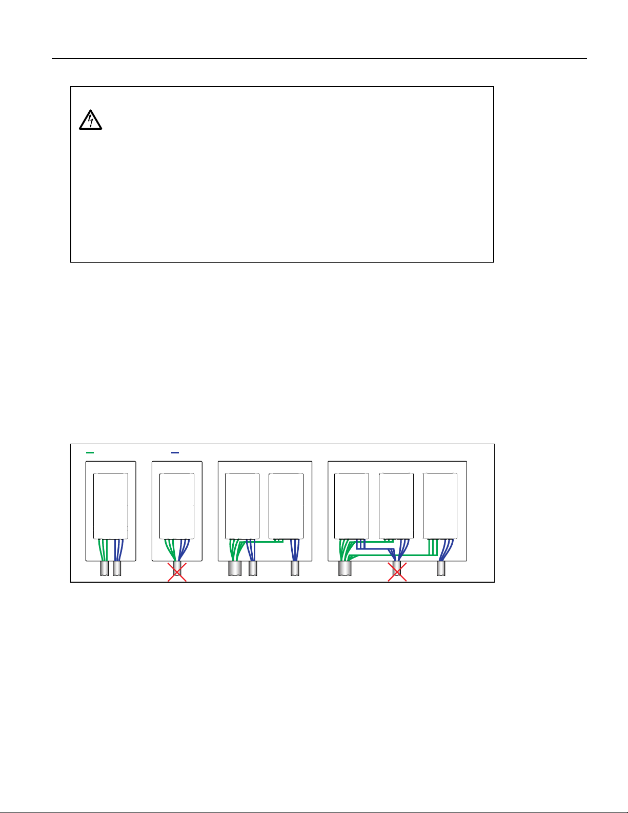
• Ensure that the system is properly grounded all the way to the
service entrance panel.
• When lifting or moving heavy components, use suitable lifting
equipment, in good condition, rated for at least 5 times the
weight of the materials being moved.
• Capacitors inside the drive can still hold lethal voltage even after
power has been disconnected—ALLOW 5 MINUTES FOR DAN-
GEROUS INTERNAL VOLTAGE TO DISCHARGE BEFORE REMOV-
ING COVER OR WORKING WITH INTERNAL COMPONENTS.
Risk of bodily injury, electric shock, or
equipment damage.
• This equipment must not be used by children or persons with
reduced physical, sensory or mental abilities, or lacking in experi-
ence and expertise, unless supervised or instructed. Children
may not use the equipment, nor may they play with the unit or in
the immediate vicinity.
• Equipment can start automatically. Lockout-Tagout before ser-
vicing equipment.
• Possible hot surfaces. Do not touch pumps during operation.
Allow all package components to cool for 30 minutes before
handling.
• Operation of this equipment requires detailed installation and
operation instructions provided in this manual for use with this
product. Read entire manual before starting installation and oper-
ation. End User should receive and retain manual for future use.
Risk of damage to pump or other equipment.
• Periodically inspect pump and system components. Regularly
check hoses for weakness or wear, making certain that all con-
nections are secure.

PRODUCT INFORMATION
Description
5
PRODUCT INFORMATION
Description
ElectricPAK™ VFD includes a Franklin Electric Cerus X-Drive VFD (Variable Frequency Drive)
control panel with touchscreen Pioneer SmartPrime™ HMI (Human Machine Interface).
Pioneer VFDs are available to control pump packages with electric motors from 25 to 350
horsepower. An inverter duty motor is recommended to ensure compatibility with VFD oper-
ation. This product is suitable for pumping applications that requires either manual speed
control or autonomous operation driven by floats and/or transducers (level, pressure, and
flow transducers are supported). The X-Drive VFD control panel is designed to control and
protect the pump motors. For more information and aid during installation or maintenance,
refer to the Cerus X-Drive owner’s manual.
The innovative package was designed with easy of use in mind, giving the users a fully
touchscreen, colored HMI for navigating and controlling the VFD. This control screen allows
the user to easily program VFD parameters, including motor nameplate data, and operate
the drive in manual and auto modes, which enables float and transducer control.
Refer to the Cerus X-Drive owner’s manual for its warranty information. The pump package is
covered under the Pioneer package warranty. For more information, see the package
owner’s manual.
Specifications
IMPORTANT: Review all included documents for important safety and operating instructions. Retain the
documents for future use.
Model Volts HZ Max HP Amps Panel Weight
(lbs) Skid Weight
(lbs)
V050-PPI-01
460 60
50 65.7 410
798
V075-PPI-01 75 96.7 458
V100-PPI-01 100 126 558
V150-PPI-01 150 182 631
V250-PPI-01 250 307 1392 1467
V350-PPI-01 350 419 1427

UNPACKING & INSPECTION
Transportation and Storage
6
UNPACKING & INSPECTION
Transportation and Storage
IMPORTANT: It is recommended to charge a stored drive every 2 years to avoid performance degradation of
its capacitors. Refer to the Cerus X-Drive owner’s manual for instructions.
Ensure the Pioneer Portable VFD is stored in a cool, dry location, protected from precipitation, dirt, vibra-
tion, and extreme temperatures. When transporting the Pioneer VFD, ensure that tie downs are secured.
Store the VFD in its shipping carton or crate in an environment that meets the following requirements:
IMPORTANT: Verify the drive door is closed during transport and storage.
Unpacking
1. Check for missing and damaged parts. Immediately report any issues to the transport company and
equipment manufacturer.
2. Examine the drive upon arrival for shipping damage.
• If there is damage, notify the shipping agent and your sales representative.
Lifting
IMPORTANT: A packaged unit should only be lifted by the lifting points on the package.
• For units mounted to an ElectricPAK™, use the lifting bail.
• For skid-mounted units, use the roof lifting eye.
• For an unpackaged ElectricPAK™ VFD, use the lifting eyes on the roof of the panel.
• Fork pockets are included on skid packages to allow transportation by forklift.
IMPORTANT: All handling must be conducted by personnel who are forklift certified.
Risk of severe injury or death.
• When lifting or moving heavy components, use suitable lifting equipment, in good condition, rated for at least 5 times the
weight of the materials being moved.
• Improper handling of the equipment may result in bodily injury or property damage.
• When lifting the pump, securely fasten it using to equipment rated to handle the pump's weight using the lifting handle.
• Never lift the pump by its cord.
Risk of damage to equipment.
• Ensure that the pump is securely fastened in either a vertical or horizontal position for transportation so that it does not roll
or fall over.
• If the pump package is dropped, impacted, or otherwise mishandled, malfunction can occur.
Storage Temperature -13 to 158 °F (-25 to 70 °C)
Location Pollution Degree 2 Environment
Relative Humidity 95% Maximum relative humidity (non-condensing)
Risk of personal injury or damage to VFD or other equipment.
• Use suitable lifting equipment, in good condition, rated for at least 5 times the weight of the VFD.

INSTALLATION
Environmental Requirements
7
INSTALLATION
Environmental Requirements
The VFD must be installed and used in a controlled environment that meets the following requirements:
Special Considerations for Outdoor Use
The drive is suitable for outdoor use with a UL TYPE 3R rating; however, the following considerations should
be made for outdoor installations:
• UL TYPE 3R enclosures are capable of withstanding downward-directed rain only.
• Protect from hose-directed or sprayed water as well as blowing rain. Failure to do so may result in drive
failure.
• Install away from direct sunlight or locations subject to extreme temperatures or humidity.
• Ensure the filters for the fan system are regularly inspected and changed at least every 3 months.
Increased replacement of filters is recommended if the drive is in a high smoke, dust environment, or
other extreme situations. Refer to “Air Filter Replacement” on page 32.
IMPORTANT: When possible, install the VFD facing away from the sun and in shade. Direct sunlight can
cause damage to the SmartPrime screen and can cause increased temperatures inside the VFD, which
can result in nuisance trips and damage to components.
Risk of severe injury or death by electrical shock.
• Do not use during periods of electrical storms (i.e. lightning). Environmental electricity can damage components and pose
a safety risk to the user.
Risk of damage to equipment.
• Do not use VFD in corrosive environments. If used in a corrosive environment, damage can occur to internal VFD compo-
nents.
• Limited airflow caused by clogged and/or unclean filters will cause overheating and severely damage the drive.
• Do not operate the VFD with fan filters removed. This can result in dust entering, thereby damaging the unit.
• Do not expose the HMI to direct sunlight. The HMI cover is designed to limit UV exposure on the HMI and should be kept
closed when the HMI is not in use.
• The drive electronics are air-cooled. Do not block fan vents or components may overheat.
• When installing a VFD in a location with high wind, minimize the exposure of the panel to wind. High winds could cause
the panel to tip and damage VFD components.
• Placing the skid on an uneven location can create a tipping hazard.
• Do not wash unit with a hose or pressure washer. The VFD is rated to UL TYPE 3R to prevent entry of environmental water,
but washing with a hose or pressure washer can damage the unit.
Max. Ambient Temperature 122 °F (50 °C)
Location Pollution Degree 2 Environment
Install away from direct sunlight.
Altitude 3281 ft (1000 m) above sea level. De-rate current 1% per 328 ft (100 m) from
3281 - 6562 ft (1000 to 2000 m). Consult Technical Support for installations
above 6562 ft (2000 m).
Relative Humidity 95% Maximum relative humidity (non-condensing)
Vibration 1.0 mm, peak to peak value range from 2 Hz to 13.2 Hz
0.7G-1.0G range from 13.2 Hz to 55 Hz
1.0G range from 55 Hz to 512 Hz

INSTALLATION
Physical Installation
8
Physical Installation
1. Place skid on a flat, level surface, clear of rocks and debris under the skid.
• Refer to “Environmental Requirements” on page 7.
• Refer to “Lifting” on page 6.
2. If applicable, connect level float switche(s) to the system.
• To complete configuration, refer to “Float Control Configuration” on page 17.
3. If applicable, connect a control transducer to the system for autonomous operation into Analog 1 on the
sensor input panel.
• Refer to “Transducer Application Setup” on page 17.
Risk of severe injury or death.
• When lifting or moving heavy components, use suitable lifting equipment, in good condition, rated for at least 5 times the
weight of the materials being moved.
• Operate the VFD with door closed and locked at all times.
• Placing the skid on an uneven location can create a tipping hazard.
Risk of bodily injury or property damage.
• Pumps can develop very high pressure in some situations. Always install a pressure relief valve able to pass the full pump
flow.
• Install the pressure relief valve near the pressure tank and route to a drain capable of full system flow.
• Ensure that the foundation is rated to accommodate the operating weight of the package and that it is sized sufficiently for
the weight and loads the package will experience.
• Do not over tighten piping connections on the fittings used to connect the site plumbing to each header as this could dam-
age the equipment and/or headers.
Risk of damage to equipment.
• The drive electronics are air-cooled. Do not block fan vents or components may overheat.
• Placing the skid on an uneven location can create a tipping hazard.
• Do not remove the HMI cover or leave open for extended periods of time. This can result in damage to the screen.

INSTALLATION
Electrical Installation
9
Electrical Installation
1. Refer to the Cerus X-Drive owner's manual and the motor's manual for proper electrical instructions,
system installation, operation, programming, and important safety instructions to avoid hazards.
2. For power, data, and ground connections, each cable to use UL Listed Series 16 cam-lock connectors
rated Type 3R that properly mate with panel connectors provided.
3. Provide minimum power and ground cable specifications, such as one with:
• UL Listed cable
• Rated min 600V
• AWG size suitable for panel nameplate current
• -25 °C to 75 °C minimum
• Suitable for hard usage
• Sun and water resistant.
Wiring Instructions
1. Ensure that ground cables are correctly connected to the drive and motor.
• The ground cable is clearly labeled on the connection plate.
• Failure to correctly connect ground cable can result in damage to the unit and safety hazard.
2. Always connect the ground wire first, as marked on the product.
IMPORTANT: Be sure to disconnect the ground wire last.
3. Make sure wiring is protected from job site equipment or other hazards that could damage the power
and ground cables.
4. For stand-alone systems:
• Output wires from a single drive may be bundled together, but must be one foot away from all
other wires.
• All wires must be at least one foot away from any wiring of other drive systems.
• Input and output wires must not be in the same conduit or wire trench.
Risk of severe injury or death by electrical shock.
• To minimize risk of electrical shock, disconnect power before working on or around the system.
• Capacitors inside the drive can still hold lethal voltage even after power has been disconnected—ALLOW 5 MINUTES FOR
DANGEROUS INTERNAL VOLTAGE TO DISCHARGE BEFORE REMOVING COVER OR WORKING WITH INTERNAL COMPO-
NENTS.
• Once site power has been provided to the control panel and those feeds are live, there will be energized electrical lines in
the control panel up to the remote disconnect terminals even when the panel's remote disconnect switch is off. Always de-
energize the site power feeding the control panel when opening the panel; otherwise, an electrical shock hazard will still
exist which can cause serious injury, death and major property damage.
• Make sure power cables are not frayed or damaged in any other way. Exposed electrical cables can cause electrical shock.
• Operate the VFD with door closed and locked at all times. Operating the drive with the door open should only be con-
ducted by trained personnel.
Incoming Power Wires Output Load Wires
ضضض ض ض

INSTALLATION
Electrical Installation
10
Motor Rotation
Always make sure the motor is not spinning backwards. Refer to “Manual Control Buttons” on page 22 to
reverse the motor’s rotation via the SmartPrime screen.
To reverse motor rotation without the HMI:
1. Turn off power to the ElectricPAK™ VFD.
2. Unplug two of the three power cables and plug them into the opposite camlock connection.
IMPORTANT: Do not swap the ground cable.
3. Turn power back on to the ElectricPAK™ VFD.
4. Start package and double check rotation.

DRIVE CONFIGURATION
Home Screen Navigation
11
DRIVE CONFIGURATION
Home Screen Navigation
1. Current date and time
2. Manual: navigation to the manual mode control screen. Refer to “Manual Mode” on page 21.
3. Auto: opens the autonomous control screen. Refer to “Auto Mode” on page 24.
4. Settings: screen that provides options for system setup of the drive and pump parameters, including
motor, sensors, throttling, autonomous behaviors, etc.
5. Data Logs: access to monitoring values as they are recorded. Refer to “Data Logs” on page 30.
6. Help: navigation to the Help screen. Refer to “Help Screen” on page 31.
7. Alarms: Refer to “Alarms Screen” on page 31.
Risk of damage to equipment.
• To prevent damaging the VFD's HMI control source, only use of fingers or proper pointing devices such as those with rub-
ber tips, should be used on the touchscreen. Using pencils, pens, and screwdrivers could result in damaging the screen.
1
2 3
4 5
6 7

DRIVE CONFIGURATION
Changing Date & Time
12
Changing Date & Time
1. Press on the current time on the Home Screen.
2. Edit settings using touchscreen.
3. Close the window.
3
1

DRIVE CONFIGURATION
Setting Operating Parameters
13
Setting Operating Parameters
Motor Configuration
ElectricPAK™ Motor Setup
1. From the Home screen, select the Settings icon.
2. Press the Motor icon to navigate to the settings screen.
NOTE: The Motor settings screen can also be accessed from the control screen of manual or auto modes.
3. Verify ElectricPAK is selected under Motor Input Option.
4. Look for the six digit identifier code on the ElectricPAK™ unit.
5. Press Motor Identifier on the screen.
6. Use the keypad to enter the identifier number.
7. Press ENT.
8. Confirm the motor settings updated to match the ElectricPAK™ motor.
9. Press Back to return to previous screen.
Risk of damage to equipment.
• Motor settings must always be checked for accuracy anytime a change in motor is connected to the package.
• Confirm motor settings every time the unit is started. It is critical that the motor settings be correct when the unit is
started. Failure to add the correct motor parameters can result in damage to the unit.
3
5
8
9

DRIVE CONFIGURATION
Setting Operating Parameters
14
Non-ElectricPAK™ Motor Setup
1. From the Home screen, select the Settings icon.
2. Press the Motor icon to navigate to the settings screen.
NOTE: The Motor settings screen can also be accessed from the control screen of manual or auto modes.
3. Use the Motor Input Option drop-down to select Enter Motor Nameplate Settings.
4. Enter each motor setting manually so it matches the nameplate on the motor.
• Press on the setting to display a numeric keypad.
• Edit the setting.
• Press ENT to confirm.
5. Check that each setting matches the motor nameplate.
6. Press Back to return to previous screen.
3
5
6

DRIVE CONFIGURATION
Setting Operating Parameters
15
Sensor Setup
NOTE: Analog 1 is the designated control input for transducers. In Auto Mode, this input can be monitored
and used to control the run state and speed of the pump. Refer to “Auto Mode” on page 24 to for informa-
tion.
1. From the Home screen, select the Settings icon.
2. Press the Sensors icon on the Settings screen.
3. Select an analog input to assign a sensor to it.
4. Select the appropriate description from the drop-down menu.
• Options include Level, Discharge Pressure, Suction Pressure, and Flow.
NOTE: Flow can only be selected for Analog sensors 2, 3, and 4 for monitoring purposes only.
5. Set the Range Min by pressing the input box and entering the associated sensor value.
NOTE: Analog 1 can only accept sensors with a minimum value of 0.
6. Set the Range Max by pressing the input box and entering the associated sensor value.
7. Select the appropriate units from the drop-down menu.
8. Press the button in the right-hand corner to view the M12 CONNECTOR
PIONOUT ANALOG INPUTS diagram.
4
5
6
7
8
2

DRIVE CONFIGURATION
Auto Mode Settings Screen Navigation
16
Auto Mode Settings Screen Navigation
1. Pumping Behavior: set up the pump application.
•Empty: to have the pump empty a water source. It is usually used when control sensors are installed
on the suction side of the pump. A typical application would be wastewater bypass.
•Fill: to fill the location where the floats are installed. It is usually used when control sensors are
installed on the discharge side of the pump. A typical application would be tank fill.
2. Control Sensor: set up what will control the pump:
•Analog 1: controlled via an analog sensor connected to Analog 1 port on the sensor input panel.
•Float(s): controlled via 1 or 2 float switches connected to port “Floats” on the sensor input panel.
Refer to “Float Setup” on page 17.
3. Backup Float: select whether the system will include a backup float for high level control. If Active is
chosen, when the backup float is in use it will trigger Emergency Backup Float control.
4. Monitoring Behavior: select how Auto mode will control the speed and ON/OFF setting of the pump.
•Maintain Level: based on user defined water level setpoint.
•Maintain Pressure: based on user defined pressure setpoint
5. Sleep Mode: Available when Analog 1 is the control source. When disabled, the pump will run continu-
ously.
•Sleep Only: When the pump is at PID Low Freq Limit and the Level or Pressure setpoint is main-
tained, the pump will enter sleep mode.
•Sleep + Boost: When the pump is at PID Low Freq Limit and the Level or Pressure setpoint is main-
tained, the pump will speed up to add an additional boost to the setpoint and then enter sleep
mode. Sleep Boost and Sleep Boost Timer can be found in Advanced Settings.
6. Action if Control Fails: Available only when Analog 1 is the control source and no backup float is chosen.
•Hold Speed: Pump continues operating at the current speed setting when the input signal was lost. If
input signal returns, auto control will resume.
•Decel Stop: Pump decelerates over the Decel Time set in Advanced Settings and then stops. If input
signal returns, auto control will resume.
•Fault Stop: Pump is immediately called to stop and a fault is issued. The fault must be cleared manu-
ally and auto control must be re-enabled to resume.
7. Sensor Status button: Refer to “Sensor Status Screen” on page 29.
1 2 3
4 5 6
7

DRIVE CONFIGURATION
Float Control Configuration
17
Float Control Configuration
Float Setup
NOTE: No more than 2 floats can be configured to be used in the system during Auto mode.
1. From the Home screen, select the Settings icon.
• Refer to “Home Screen Navigation” on page 11.
2. Press the Sensors icon on the Settings screen.
3. Set each float switch type as Normally Open or Normally Closed.
4. Press OK in the pop-up menu to confirm selection.
Auto Mode Float Configuration
1. Press Auto Mode Setup.
2. Set Pumping Behavior: refer to “Auto Mode Settings Screen Navigation” on page 16.
•Empty: to empty or draw down the location where the floats are installed.
•Fill: to fill the location where the floats are installed.
3. Set Control Sensor as Float(s).
4. Set Monitoring Behavior as Maintain Level.
5. For Float Configuration, choose Single Float or Dual Float depending on the number of floats needed.
6. To start the system, refer to “Float Control Application Startup” on page 25.
Transducer Application Setup
1. Plug in a level transducer to Analog 1 on the sensor input panel.
2. From the Home screen, press Settings.
3. If not already completed, press the Motor Settings button to set up the motor.
• Refer to “Motor Configuration” on page 13.
• Press Back when finished.
4. Press the Sensors button.
3
2

DRIVE CONFIGURATION
Transducer Application Setup
18
5. Under Description, choose applicable setting:
• For level transducer control applications, choose Level.
• For discharge pressure control applications choose Discharge Pressure.
6. Enter the maximum range for the transducer.
7. Choose the appropriate units to match the level transducer.
8. Repeat for any additional sensors connected to the sensor input panel.
9. Press the Home button.
Level Transducer Control Configuration
NOTE: Be sure the transducer is set up. Refer to “Transducer Application Setup” on page 17.
Auto Mode without Backup Float Configuration
1. Press the Auto Mode button.
2. Press Auto Mode Setup.
3. Set Pumping Behavior: refer to “Auto Mode Settings Screen Navigation” on page 16.
4. Set Control Sensor as Analog 1.
5. For Backup Float, select None.
6. For Action if Control Fails, choose what would happen if the control signal is lost.
• Refer to “Auto Mode Settings Screen Navigation” on page 16 for details on each option.
7. For Sleep Mode, choose the conditions to put the pump to sleep.
• Refer to “Auto Mode Settings Screen Navigation” on page 16.
8. Set Monitoring Behavior as Maintain Level.
9. To start the system, refer to “Level Transducer Control Startup” on page 26.
Auto Mode with a Backup Float Configuration
1. Press the Auto Mode button.
2. Press Auto Mode Setup.
3. Set Pumping Behavior:
•Empty: to empty or draw down the location where the floats are installed.
IMPORTANT: The backup float must be Normally Open for Empty applications.
•Fill: to fill the location where the floats are installed.
IMPORTANT: The backup float must be Normally Closed for Fill applications.
4. Set Control Sensor as Analog 1.
5. For Backup Float, select Active.
6. Set Float Configuration as Single Float.
7. For Sleep Mode, choose whether the pump should be allowed to sleep.
• Refer to “Auto Mode Settings Screen Navigation” on page 16.
8. Set Monitoring Behavior as Maintain Level.
9. To start the system, refer to “Level Transducer Control Startup” on page 26.
Normal Operation
High Level Emergency Mode Engaged
Fill Applications
High Level Emergency Mode Engaged
Normal Operation
Empty Applications
Backup Float
Switch Open Backup Float
Switch Closed
Backup Float
Switch Closed
Backup Float
Switch Open

DRIVE CONFIGURATION
Advanced Settings
19
Discharge Pressure Transducer Configuration
NOTE: Be sure the transducer is set up before configuration. Refer to “Transducer Application Setup” on
page 17.
1. Press the Auto Mode button.
2. Press Auto Mode Setup.
3. Set Pumping Behavior as Fill.
4. Set Control Sensor as Analog 1.
5. Make sure None is selected for Backup Float.
6. Choose Single Float for Float Configuration.
7. For Action if Control Fails, choose what would happen if the control signal is lost.
• Refer to “Auto Mode Settings Screen Navigation” on page 16 for details.
8. For Sleep Mode, choose whether the pump should be allowed to sleep.
• Refer to “Auto Mode Settings Screen Navigation” on page 16 for details.
9. Set Monitoring Behavior as Maintain Pressure.
10. To start the system, refer to “Discharge Pressure Transducer Control Startup” on page 27.
Advanced Settings
For complete list of advanced parameters, refer to “Advanced Settings Reference” on page 35.
1. From the Home screen, select the Settings icon.
2. From the Settings screen, select the Advanced icon.
3. Enter the login information.
NOTE: To change the password, press the Change Password button, and refer to “Changing Advanced
Settings Password” on page 20.
4. Select the desired parameter to edit.
5. Press the Advanced Settings 2 button to edit Sleep Check Time (s), Sleep Bump Timer, Sleep Delay (s),
Sleep Boost Value, Wake-Up Level, Sleep Boost Timer, and Over Pressure Timer.
• On this screen, there is an Advanced Settings 1 button in the bottom left corner to go back.
6. Press the Settings button to go back to the settings screen.
7. Hit the Home button at the bottom of the screen to return to the main screen.
56 7
3
2

DRIVE CONFIGURATION
Advanced Settings
20
Changing Advanced Settings Password
1. On the Advanced Settings 1 page, press Change Password in the upper right corner of the screen.
• Refer to “Advanced Settings” on page 19.
2. Input the current ADMIN login information.
• Default setting for Account is ADMIN
• Default password is ADMIN.
• Both are all UPPERCASE.
3. Change Level 0 to Level 1.
4. Press on the current password.
5. Input the desired new ADMIN password.
6. Exit the change password screen.
2
6
This manual suits for next models
5
Table of contents
Languages:
Other Pioneer Water Pump manuals
Popular Water Pump manuals by other brands

Dover
Dover PSG ALL-FLO IOM A100 Series Installation operation & maintenance data

ProMinent
ProMinent Makro/ 5 M5Ka operating instructions

JABSCO
JABSCO 30580 Series manual

Kärcher
Kärcher SP 16.000 Dual manual

Agilent Technologies
Agilent Technologies 1260 Infinity II user manual

Xylem
Xylem IM127R07 Installation, operation and maintenance instructions