PiXORD P-500 User manual

PiXORD
Dual Streaming Network Camera /
Video Server
P-500/1500
User’s Manual
Version: 1.0
Date: 02/20/2008

- 1 -
CONTENTS
CHAPTER 1 INTRODUCTION................................................................................................................................-2-
1. WHAT IS PIXORD DUAL STREAMING NETWORK CAMERA/VIDEO SERVER?.....................................................- 2-
2. FEATURES..........................................................................................................................................................- 3-
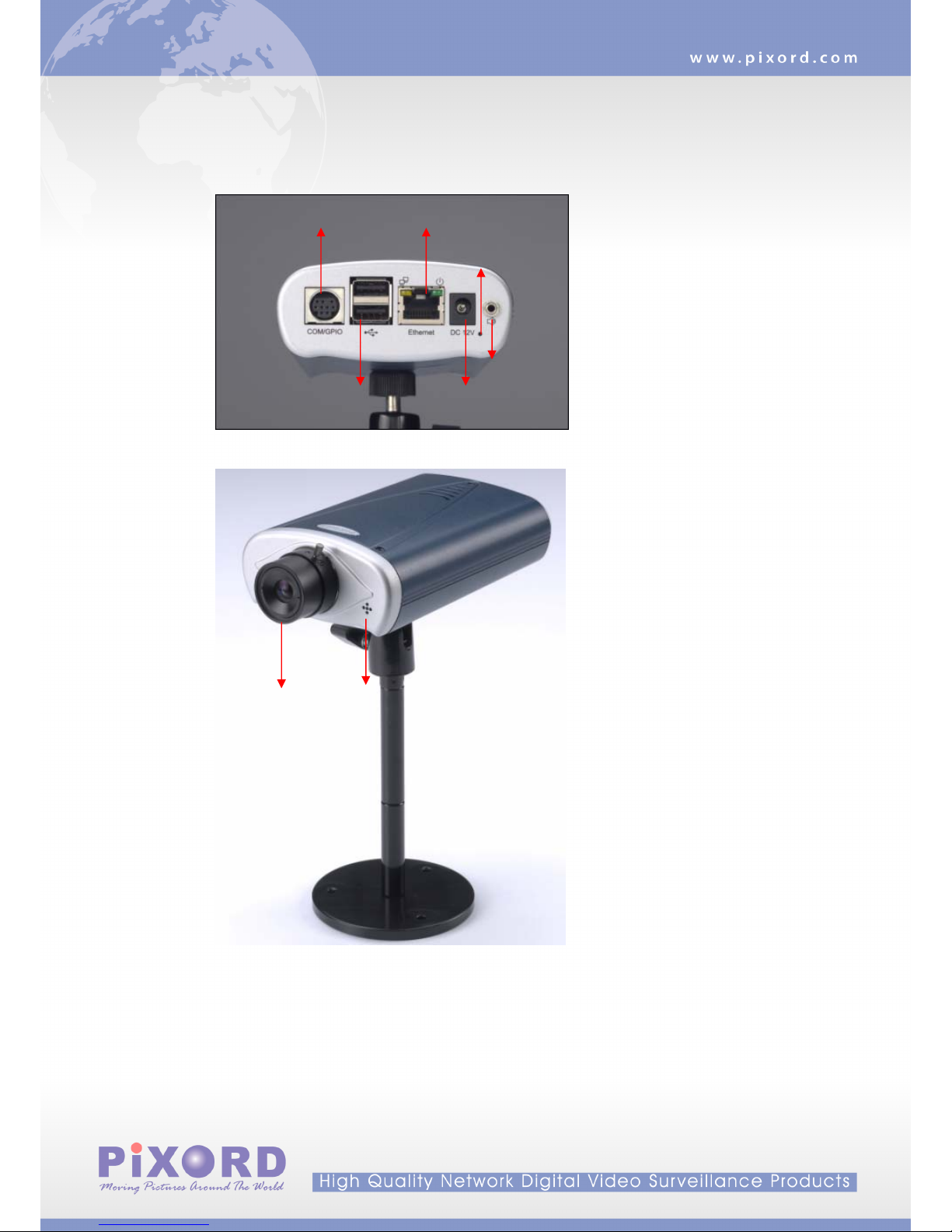
CHAPTER 2 PHYSICAL IMAGES .......................................................................................................................... - 4 -
1. P1500 VIDEO SERVER .......................................................................................................................................- 4-
2. P500 NETWORK CAMERA .................................................................................................................................- 5-
CHAPTER 3 INSTALLATION.................................................................................................................................. - 6 -
1. HARDWARE CONNECTION..................................................................................................................................- 6-
2. SOFTWARE INSTALLATION.................................................................................................................................- 7-
3. NETWORK CONFIGURATION ..............................................................................................................................- 9-
CHAPTER 4 USINGTHE WEB UI........................................................................................................................ - 13 -
1. LIVE VIEW ......................................................................................................................................................- 14 -
2. PLAYBACK ......................................................................................................................................................- 17 -
3. CONFIGURATION PAGE.....................................................................................................................................- 22 -
CHAPTER 5 CONFIGURE THE SETTINGS WITH WEB UI............................................................................ - 23 -
1. SUB ITEMS.......................................................................................................................................................- 23 -
2. VIDEO SETUP (AVAILABLE FOR ADMINISTRATOR ONLY)..................................................................................- 24 -
3. CAMERA SETUP...............................................................................................................................................- 26 -
4. EVENT SETUP..................................................................................................................................................- 29 -
5. SYSTEM SETUP....................................................................................................................................................35
6. NETWORK SETUP ................................................................................................................................................42
7. STORAGE SETUP..................................................................................................................................................48
APPENDIX A SPECIFICATIONS................................................................................................................................50
1. P500....................................................................................................................................................................50
2. P1500..................................................................................................................................................................52
APPENDIX B THE MINI DIN CONNECTOR...........................................................................................................53
APPENDIX C FAQ.........................................................................................................................................................55
1. HOW CAN ISET FACTORY DEFAULT?....................................................................................................................55
2. HOW TO CHANGE THE TV STANDARD (P1500 ONLY)...........................................................................................57
3. HOW TO UPGRADE FIRMWARE FOR THE DEVICE?.................................................................................................58
4. WHYACTIVEXREMAINS IN OLD VERSIONAFTER UPGRADING TO NEW VERSION FIRMWARE?..............................60

- 2 -
Chapter 1
Introduction
1. What is PiXORD Dual Streaming Network Camera/Video Server?
The PiXORD 500 (Network Camera, hereinafter called P500) and 1500 (Network Video Server,
hereinafter called P1500) are professional MPEG-4/MJPEG dual streaming surveillance products. Dual
streaming allows seamless remote video monitoring using MPEG-4/MJPEG concurrently with
transmission of high quality MPEG-4 stream to an optional storage. The audio stream can also be
compressed and distributed over Intranet/Internet as the result of capable being recorded. Both P500 and
P1500 have 2 USB 2.0 host ports; with external storage connected the video/audio can be recorded
locally. For power solution, while normal adapter is applied for both devices they also come with the
optional PoE model. The P500/1500 successfully provides the solution of remote monitoring and quality
recording in surveillance.

- 3 -
2. Features
Self-Contained Web Server providing Internet capability for remote access
MPEG-4 ASP / MJPEG dual compression formats
Simultaneous MPEG-4 and MJPEG stream for multiple clients
Supports up to 30/25 FPS at Full D1 resolution
More than 480 TV lines resolution (P500)
Built-in internal microphone (P500)
Event handling trigger by alarm/motion and action to send video clip by Email / FTP
Two USB 2.0 Host ports support external storage and/or wireless USB connection (to be firmware
upgraded)
IP setup by easy IP Installer / DHCP / Static IP / PPPoE
Supports DDNS for dynamic IP application
NTP (network time server) with DST supported which provide accurate unify system time
Hardware watchdog providing robustness system in critical environment

Chapter 2
Physical Images
1. P1500 Video Server
COM/ GPIO LAN Port
Reset hole
USB Ports Power Jack
Audio Output
Video Input
Video Output Audio Input
NTSC/PAL Switch
- 4 -

2. P500 Network Camera
COM/ GPIO LAN Port
Audio Line Out
Reset hole
USB Ports Power Jack
Camera Lens Built-In Microphone
- 5 -

Chapter 3
Installation
1. Hardware connection
Physical connection of P1500 video server
1. Prepare a PC with Ethernet link to the network
2. Connect P1500 device to a network hub/switch with standard pass through (CAT5) cable, or
connect directly to PC with a cross over cable.
3. Connect the video output of a CCD camera using standard 75 Ωcoaxial cable terminated with
BNC connector.
4. Connect power jack
- 6 -

5. Ensure the power adapter specification matches the power system (110V or 220V). Connect
the adapter to the outlet.
6. Check both LEDs (Power/Network); ensure they are light on after the steps above.
Follow the same steps as connecting P1500 video server except step 3, to perform the P500
connections.
Physical connection of P500 Camera
2. Software Installation
The following software is necessary for the proper display and use of the P500/1500 from the Web site.
- 7 -

- 8 -
The software will be taken from the Software Package CD.
IP Installer
The IP Installer is used to locate and configure network cameras and video servers on the LAN. This
utility is useful for conveniently configuring the network settings of the device, or for finding a device once
the network settings have been modified.
To install the IP Installer, from the Software Package CD UI, select IP installer, then follow the on screen
instructions.
Component Installer
The ActiveX component is used by our devices for video display and device configuration. Usually, when
you connect to the P500/1500 via IE browser, the ActiveX component will be installed automatically. If the
components can not be installed, install this software from the Software Package CD.
XVID Codec
An MPEG-4 codec is applied for displaying the video stream and playing the recoded AVI files. If the
video stream can’t be displayed or the recorded AVI files can be play on PC, install this software from the
Software Package CD.
VLC
Though not necessary, this can be used for viewing the streaming without a Web browser.

3. Network Configuration
IP Installer is a utility that provides an easier, more efficient way to configure the IP address and network
settings of the devices. It even provides a convenient way to set the network settings for multiple devices
simultaneously using the batch setting function. Moreover, IP Installer can save the network settings for
all devices as a backup and restore them when necessary.
Preparation before IP Assignment
1. Always consult your network administrator before assigning an IP address to your server in order to avoid
using a previously assigned IP address.
2. Ensure the P500/1500 is powered on and correctly connected to the network.
3. MAC Address: Each device has a unique Ethernet address (MAC address) shown on the label of the
device as the serial number (S/N) with 12 digits (e.g. 000429-XXXXXX).
- 9 -
4. Although the IP Installer is able to find and configure any P500/1500 on the LAN except those that are
behind a router, it is a good idea to set the host PC to the same subnet. In order to connect to the
Web-based user interface of P500/1500, the host PC must be in the same subnet. For more information
about subnets, please consult your network administrator.
*0004290000B1
Using IP Installer to Assign an IP Address to P500/1500
1. Once IP Installer has been successfully installed on the PC, double click the IP Installer icon on the
desktop, or select it from Start > Programs > IP Installer > IP Installer > Launch IP Installer.

2. Click the menu bar Tool > Search Network Device to search the device in the LAN.
3. From the list, select the device with the MAC Address that corresponds to the P500/1500 that is to be
configured. The MAC Address is identical to the unit’s S/N (Serial Number).
4. Double click the item to open the Property Page for the selected device or click the menu bar View >
Property.
- 10 -

5. After filling in the properties, click [Synchronize] button to complete the configuration settings in the
remote P500/1500 while saving configuration in the PC. If click [OK] button, the configuration is only be
saved in the PC.
Open the Web-based UI of the Selected P500/1500
1. To access the Web-based UI of the selected unit, run the View > Open Web on the menu bar.
2. If the device has been configured correctly, the default Web browser will open to the home page of the
selected device.
3. If you find your browser is opened and automatically connected to the P500/1500 Home Page, it means
you’ve assigned an IP Address to the unit successfully. Now you can close the IP Installer and start to use
your P500/1500.
- 11 -

- 12 -
Verify and Complete the Installation from Your Browser
When browsing the Home Page at the first time with the Microsoft Internet Explorer TM, you must temporarily
lower your security settings to perform a one-time-only installation of the ActiveX component onto your
workstation, as described below:
1. From the Tools menu, select [Internet Options]
2. Click the [Security] tab and then click [Custom Level] button to see your current security settings.
3. Set the security level to Low and click [OK].
4. Type the URL or IP address of your P500/1500 into the Address field.
5. A dialog box will pop up asking if the ActiveX control should be installed. Click [Yes] to start the
installation.
6. Once the ActiveX installation is complete, return the security settings to their original value, as noted
above.

Chapter 4
Using the Web UI
Start your Web browser and enter the URL or IP address in the Address field. The Home page of the
P500/1500 is now displayed.
The status of the
video stream
The display of channel information can be
configured in the OSD setting, including
video status, channel number, camera title,
frame rate and transfer speed (bit rate).
Note: Please notice to install the version of XVID codec and recommends V1.1 above, it can be found in the
CD package.
- 13 -

1. Live View
Functions in live view page
The following are the available keys in the Live View mode:
Button Description
Select the display language for web user interface
Check “Actual Size” to display the video stream at the actual resolution
Check “Audio” to enable audio recording.
Click “Rotation” to rotate the selected video on 90 degrees clockwise direction.
Click “Record” to start/stop recording.
Click “PTZ” to show up a panel for the PTZ operation.
- 14 -

Click “Deinterlace” to expend the option of deinterlace On/Off
Users need to set the file path before taking the snapshot. Click on [BMP] or [JPEG]
to take an image with the bmp or jpeg file format respectively.
Set the recording parameters including the recording path, file name, total file
space, maximum file length, enabling/disabling cycle recording and synchronize to
timestamp. Click on “Setting” to apply the change.
Go to the Playback page for search and play back recorded video file
Note: The user that log in with user account* can’t use the Playback function
Go to the Configuration page for setup
Note: The user that log in with user account* won’t have an access to this page
* P500/1500 user setting can be categorized in three groups, the Admin, operator and user. Detail
description can be found in Configuration page > System > User.
- 15 -

P/T/Z Control for Dome Camera
The following are the available keys to control the PTZ dome camera:
Button Description
Select the preset point for quick view or setup
Click on the arrow buttons to move the camera to that direction
Click on the rectangle button to stop the movement
Zoom
Zoom out the video
Zoom in the video
Stop the adjustment
Iris
Open the iris and reduce glare
Open the iris and brighten the picture
Stop the adjustment
Focus
The target will become farther
The target will become nearer
Stop the adjustment
Auto Pan
Activate the auto pan function
Stop the auto pan function
Save Click this button will save the current data as a preset point
- 16 -

2. Playback
To play back the recorded file, click the button in Home page
- 17 -
Button Description
This will be displaying playback status include the speed
of playing, playing mode and name of the controlling user.
Select “Record HDD” or “Backup HDD” to search for the
recorded file. Click [Search] button to open the Search
panel, see Figure 1.
Click this button to expand a setting panel for recording
the playback stream to the client PC, see Figure 3.
Click this button back to the Live View mode
Go to the Configuration page for setup
Note: only 1 user can control play back streaming in a meantime. Other than the first user will be able to see
the playing only (not to control) and who is controlling.
For the first user (must at least have an operator authority) going to start playback:
1. Select the hard disk that will be searched for.
2. Click Search button to open the Date/Time panel for choosing.
3. Select by Date/Time in the calendar. To know the usage of the calendar, just move the cursor on the
button, the tips for the button will appear.
4. After select the Date/Time, click on [Begin Playback] button to playback all recorded video from the
selected time or [Event list] button to choose the recorded video files from events list, see figure 1& 2.
For other clients (even logged in as an administrator)
As one user is controlling the playback, the other clients must wait until the user stops the playback function.
During the waiting time these clients can only view the streaming of playback.

Close this panel
The start and end time of the all video recordin
g
The start time of the recording you can manual input
or click calendar to play
The event type of the recording you can select to play
Status of control playback
You can click this to change play time
You can click this to increase of number or press button
of “Shift” and click this to decrease of number
You can click button of “Begin Playback” to play time or
click “Event List” to play event list
Figure 1
- 18 -
Current page Total page “Next“” button
Event List
Item
Channel
Event Type
Duration
Event Time
Event Date
Figure 2

Playback Screen
Controller’s View
Other clients’ View
- 19 -
This manual suits for next models
1
Table of contents
Other PiXORD Server manuals