Planer kryo connect User manual

kryo·connect™
Getting Started . . .
MA009170 issue 004

© 2004 Planer plc
Planer plc, 110 Windmill Road, Sunbury, Middlesex, TW16 7HD, UK.
Telephone: +44 (0)1932 755000
Facsimile: +44 (0)1932 755001
Web: www.planer.co.uk
kryo·connect is a trademark of Planer plc.
Microsoft, Windows and Windows NT are either registered trademarks or
trademarks of Microsoft Corporation in the United States and/or other
countries.
Java is a trademark or registered trademark of Sun Microsystems, Inc. in the
United States and other countries.
IBM is a trademark or registered trademark of IBM Corporation in the
United States and/or other countries.
Lotus, Lotus Notes and Domino are trademarks of Lotus Development
Corporation.
Linux is a registered trademark of Linus Torvalds.
All other trademarks are the property of their respective owners.
Planer plc. reserve the right to alter products and their specifications without
notice.

Getting Started
1
Contents
GETTING STARTED 2
Symbols used in this guide 2
Symbols & legends used on the kryo·connect 2
Notices 3
Introduction 3
Connections and Indicators 4
Minimum System Requirements 5
Network: 5
Client PC: 5
Administrator's PC 5
Connecting to the network 6
Preparing for Configuration 7
Starting kryo-connect Configurator software 8
On a PC running Windows 32 8
On a PC running Linux 8
Running kryo-connect Configurator 9
Starting the web server 10
Configuration Details 11
Contact Details 12
Technical support: 12
Sales: 12
Ethernet Cables 13
RS232 / RS485 Connections 14
General Terms 15
LICENCE AGREEMENT 15
TERM 16
THE SOFTWARE WARRANTY 16
LIMITATION OF REMEDIES AND LIABILITY 16
Specifications 18

Getting Started
2
Getting Started
Symbols used in this guide
Failure to follow these instructions could result in personal
injury.
Failure to follow these instructions could result in damage to
your equipment or system.
Symbols & legends used on the kryo·connect
Read the manual as failure to follow these instructions could
result in personal injury.
Ethernet 10-base T socket
Chassis terminal
DC power inlet socket. Centre positive.
RESET Reset switch. Press to reset the unit. This will cause any
changes that have not been written to the web server's permanent
memory to be lost.
RS232/485 RS232 and RS485 connector. Interface depends on the internal
DIP switch settings.
Alternating current (AC)
Direct current (DC)
Equipment protected by double or reinforced insulation.

Getting Started
3
NoticesThis product and the information, reports and e-mail messages
provided by the unit must not be used in safety critical
applications. The kryo·connect is intended for information
purposes only and must not be the sole means of monitoring
alarm and fault conditions.
Introduction
The kryo·connect is a small desktop or wall mounted unit designed to convert
an existing device with an RS232 or RS485 interface into a web server. This
allows the device to be controlled and interrogated using a standard web
browser as shown below
Clients
Intranet
kryo-connect
Host
Device

Getting Started
4
The actual operation of the software depends upon the application that has
been loaded into the unit. This is identified by the label on the end of the
unit. Once the unit is connected to your network and accessible through your
web browser, you will be able to access the online manual from the unit's
home page. This manual provides details on how to connect the unit to your
network so that the online documentation specific to the installed application
can be loaded.
Connections and Indicators
Ethernet status LEDs
RS232/485 connectorPower on indicator
DC
power
inlet
Chassis
ground
Reset switch

Getting Started
5
Minimum System Requirements
Before trying to install the kryo·connect you must ensure that your network
and client PCs meet the minimum system requirements.
Network:
•10 BaseT ethernet. Category 5e cable recommended as minimum.
•Free RJ45 Socket on hub or router located within 100m (330 feet) of the
unit.
Client PC:
•Microsoft Internet Explorer v6+ with cookies enabled and Java Virtual
Machine (VM) installed.
Administrator's PC
Please note that this PC is only required when first connecting the unit to the
network. Once the connection has been made only the standard Client PC is
required.
•32 MB RAM minimum
•Windows 95 SP1, 98 SE, NT4 + SP5, ME, 2000 + SP2, XP Home or
Professional.
•CD Drive.
•Microsoft Internet Explorer v6+ with cookies enabled and Java Virtual
Machine (VM) installed.

Getting Started
6
Connecting to the network
The only connection required from the unit to the network is the Ethernet
cable. The unit is designed for connection to information technology
equipment compliant with EN60950 or its equivalent. Use with
other equipment may compromise the safety of the device. The
unit should only be connected to an Ethernet LAN internal to the
building.
It is advisable not to permanently install the kryo-connect unit
until you have completed the network connection and reviewed
the online documentation as there may be additional installation
requirements that need to be considered.
•Locate the RJ45 network connector located in the end panel of the web
server.
RJ45 network connector
If you are connecting the unit to a network hub you will need a standard
patch cable but if you are connecting directly to a PC with an Ethernet
connection you must use a crossover patch cable. These cables are
available from Planer plc.
•Connect one end of the appropriate cable tothe unit and the other end to
the network hub or PC as shown below taking care not to touch the pins
of the connectors. NB. The length of the cable should be at least 2.5m
and less than 100m.
Standard Patch Cable
(PPL No. AC008795)
Crossover Cable
(PPL No. AC008796)
Client
PC
Hub

Getting Started
7
Should you need to create a longer cable for your installation, the connection
details are given in the sectionEthernet Cables.
Check that the voltage rating of the kryo-connect power supply
matches your mains power outlets. If not, contact your supplier
and do not continue with the installation.
The power supply is only suitable for indoor use and must be
positioned away from sources of condensation and moisture.
Any power supply connected to the kryo-connect must comply
with IEC 950 and all outputs must meet the requirements for
non-hazardous accessible parts and limited power circuits.
•If not already fitted, slide the appropriate socket adapter onto the power
supply. Ensure that it clips securely in place.
•Plug the power supplyinto an easily accessible mains power socket
located close to thekryo-connect. The power supply provided is suitable
for connection to an IT power distribution system.
•Plug the power supply's ouput lead into the DC power inlet of the kryo-
connect.
•You are now ready to set up the system so thatkryo-connect can be
recognised on the network.
Preparing for Configuration
Configuring the network settings requires knowledge of the
current network structure and IP addresses and will require
consultation with your network administrator. Incorrect settings
could result in the computer network failing to operate correctly.
The kryo-connect Configurator program is used to set up the networking
properties of the kryo-connect. The program is able to communicate at the
networking level and to configure the server with sufficient information to
present itself on an Internet Protocol (IP) based network.

Getting Started
8
kryo-connect Configurator is a Java application and is provided on the
kryo-connect Configuration CD along with the Java Runtime Environment
(JRE).
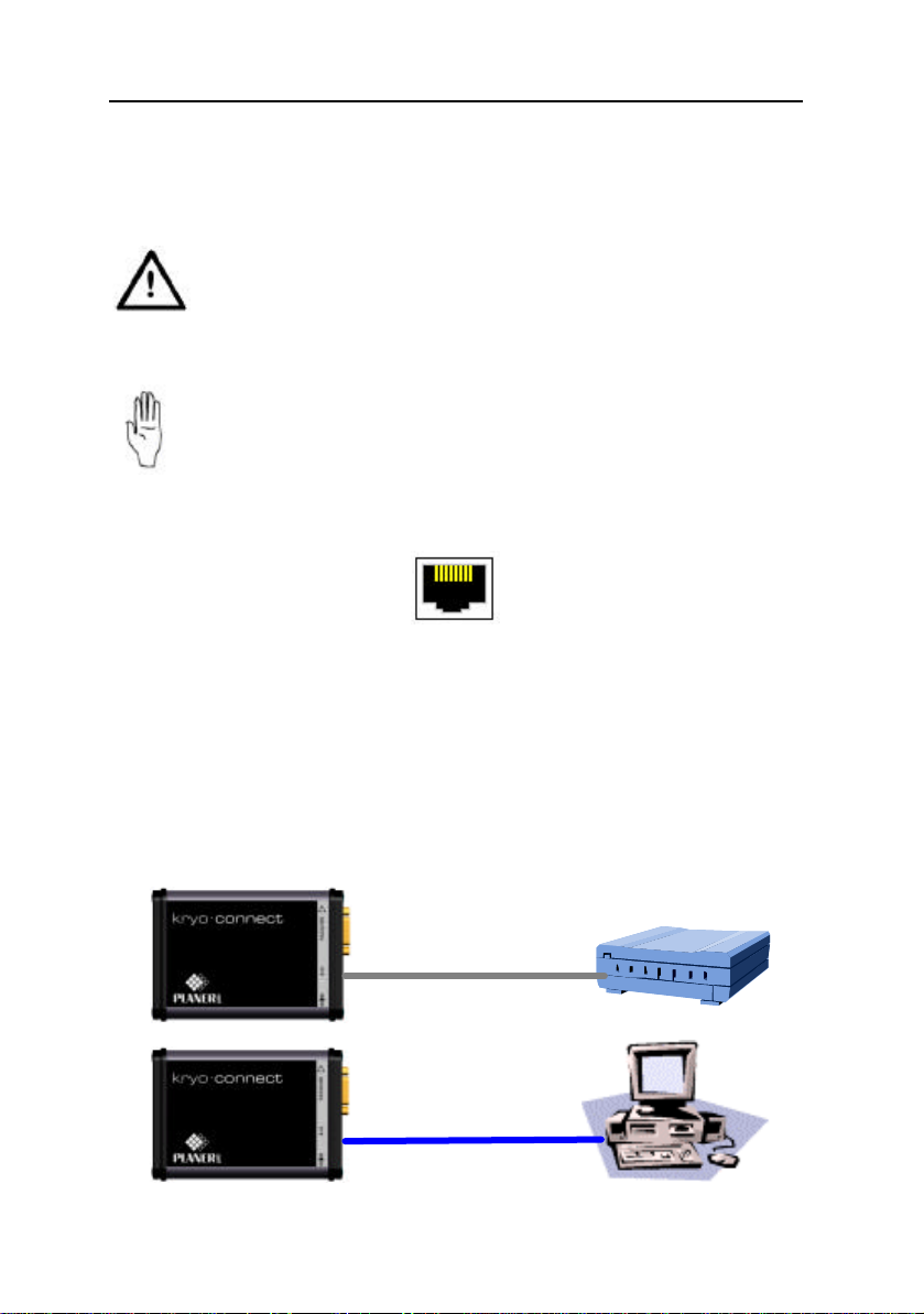
For the best results when using this software, ensure that anykryo-connect
units are located within the same network segment as the Administrator’s PC.
Note that this software may not be able to address units if a firewall or router
needs to be traversed. In this case, during configuration, you will need to
connect thekryo-connect directly to the configuration PC using the crossover
patch cable. Once configuration is complete you will be able to disconnect
the unit from the configuration PC and then reconnect it in its correct
location.
Starting kryo-connect Configurator software
•Insert thekryo-connect ConfiguratorCD into the CD drive on the PC.
On a PC running Windows 32
•You must be logged in with administrator's rights to install the program.
•The CD should start the installation program automatically.
•If the program does not start, click on the Start button on the Windows
task bar.
•Select Run from the menu.
•Click Browse, locate the CD drive and then selectthe
kcConfig_windows_x_y_z.exe file from the CD. (x_y_z is the current
version of the software.)
•From the Run dialogue box select OK to start the installation program.
•Follow the on-screen instructions.
•Once the installation is complete you will be able to start the kryo-
connect Configuratorprogram by selecting Start > Programs > kryo-
connect > kryo-connect Configuratorfrom the Windows task bar.
On a PC running Linux
•Note that although the installer does not require an X Server, the
application does.
•Log in as root and mount the CD.
•At the shell type rpm -ivh <mount point of CD>/
kcConfig_linux_x_y_z.rpm. (x_y_z is the current version of software.)
•Once the installation is complete, type /usr/local/bin/kcConfig at a shell
prompt to launch the application. (requires an X Server to run)
Now follow the steps in the sectionRunning kryo-connect Configurator.

Getting Started
9
Running kryo-connect Configurator
•In the Device serial number field enter the serial number of the device
you need to configure. The serial number is on the label on the end face
of the unit.
Network settings should only be configured by the network
administrator familiar with the network to which the kryo-
connect is being connected. Incorrect settings could result in the
computer network failing to operate correctly.
•From the window set the parameters necessary for the unit to
communicate with your network. The individual fields are described
below along with help on how they should be set.
IP Address :
Each device on your network musthave a unique IP address. Your
network administrator will need to provide you with an appropriate
address.
Network Mask :
The network mask allows the unit to determine whether it is a local
device. The correct setting for this parameter requires knowledge of the
actual network system.
Default Gateway :
When a user accessing thekryo-connect is not local, as determined by
the IP Address and Network Mask, the device entered here will be
used to route traffic to and from the user.
DNS Server :
In this location, enter the IP Address of the Domain Name Server (DNS).
This is used by thekryo-connect to resolve IP host names. Leave this as
0.0.0.0 or blank if no DNS server is used.
Once the settings have been entered into the dialogue box and reviewed,
record them in the Configuration Details section of this guide.
•Switch on the kryo-connect. The unit will take one minute to start up.
After one minute but before two minutes have elapsed, click the Apply
button to transmit the new configuration to the kryo-connect. The
program will then launch the login page for the web server application.

Getting Started
10
Note that the configuration is only temporary and will be lost if the
system is reset.
•If a connection failed page appears, check the serial number you used for
the configuration. Click Exit on thekryo-connect Configurato and then
repeat the process from the start.
•Select Exit from the kryo-connect Configuratorto close the
configuration program.
•Login to the server. If this is a new system, use the user name of
MANAGER1 with a password of password. NB. the name and
password are both case-sensitive.
•Select the User guide button from the main Welcome page and follow the
instructions for setting up the unit and making the changes permanent.
Starting the web server
•At the client PC, start your web browser.
•In the URL or web address enter the start address for kryo·connect as
recorded in the sectionConfiguration Details.
•When the Login page appears, enter your user name and password. Note
that these are case sensitive.
•From the main Welcome page, select the User guide button to access the
online help specific to the installed application.

Getting Started
11
Configuration Details
As you follow the instructions in this guide you should also complete the
details of your kryo-connect in the table below.
Serial number
IP Address [ ] [ ] [ ] [ ]
Network Mask [ ] [ ] [ ] [ ]
Default Gateway [ ] [ ] [ ] [ ]
DNS Server [ ] [ ] [ ] [ ]
URL to access the kryo-connect

Getting Started
12
Contact Details
Technical support:
E-mail: [email protected]
Telephone: +44 (0)1932 755006
Fax: +44 (0)1932 755001
Sales:
E-mail: [email protected]
Telephone: +44 (0)1932 755005
Fax: +44 (0)1932 755001

Getting Started
13
Ethernet Cables
Should you need to create your own ethernet cables, details of the pinouts are
shown below. Colours shown are to the EIA/TIA 568A colour scheme. All
connectors are shown with the clip downwards.
Standard Patch Cable Pin Colour
1White/Green White/Green
2Green Green
3White/Orange White/Orange
4Blue Blue
5White/Blue White/Blue
6Orange Orange
7White/Brown White/Brown
8Brown Brown
Crossover Patch Cable Pin Colour
1White/Green White/Orange
2Green Orange
3White/Orange White/Green
4Blue Blue
5White/Blue White/Blue
6Orange Green
7White/Brown White/Brown
8Brown Brown

Getting Started
14
RS232 / RS485 Connections
The kryo-connect is provided with a 9 way D-Type plug that can be
configured for both RS232 and RS485 interfaces. The actual configuration is
determined by dip-switches inside the unit and is normally factory
configured. The information below can be used if the configuration needs to
be changed or if interconnecting cables need to be made.
It is important that the kryo-connect is connected to ground to
prevent charge build up. On RS232 connections this is achieved
through the cable screen and signal ground. On RS485
connections, if no ground is provided through the cable, the
chassis ground should be connected to a suitable ground
reference.
Pin outsPort type DIP switch * 123456789
RS232 –
Wired as
DTE.
Requires null
modem cable
to connect to a
PC
-R
XT
X-G
N
D
-R
T
S
C
T
S
-
RS485 full
duplex tx
-rx
-tx
+rx
+
RS485 Half
duplex A
-B
+
RS485
terminate RX
120 Ohms
Connects a 120 Ohm resistor across the RX
pair
RS485
terminate TX
120 Ohms
Connects a 120 Ohm resistor across the TX
pair
* grey switches means the setting does not matter or is determined by another
requirement such as termination

Getting Started
15
General Terms
In this document the term the Software, refers to the programmes, files and
documentation provided as kryo·connect, kryo-connect Configurator and
includes software provided pre-installed in the kryo·connect or on any
separate media. Other software components supplied with kryo·connect are
owned by their respective Companies and their licences and documentation
are duly transferred in accordance with their separate licence agreements.
By installing or using the Software, you agree to the terms and conditions of
this Licence. The Software is protected by copyright laws and international
copyright treaties as well as other intellectual property laws and treaties. The
Software is licensed, not sold.
LICENCE AGREEMENT
(i) You may install the Software on a single machine only. The
Software may be transferred to and then utilised on another machine,
provided that the Software is removed from the original machine.
(ii) The Software may be accessed concurrently via a network by any
number of users up to and including the number of users for which
you have acquired a licence.
(iii) You may only make copies of the Software for the purposes of
backup.
(iv) You may not rent the Software, copy, modify, transfer or merge the
Software in whole or in part.
(v) You may not modify, decompile, disassemble, reverse engineer,
create derivative works based on, or translate the Software except
and only to the extent that such activity is expressly required by
Government Authority acting under applicable law.
(vi) You may not reproduce, distribute or alter the Software
documentation.
Your Licence and this Licence Agreement are automatically terminated with
immediate effect if you contravene any of the above conditions (i) to (vi); this
termination shall be without prejudice to any criminal, civil, or other remedy
available to Planer plc.

Getting Started
16
TERM
This Licence Agreement may be terminated by you at any time, by
destroying the Software and documentation together with all copies in
whatever form and notifying Planer plc in writing. This Licence and this
Licence Agreement will also terminate automatically and with instant effect
if you do not comply with any of the terms or conditions therein. In such
event you agree that you will destroythe Software and all copies in any form,
without delay, and that you will provide Planer plc with a written statement
confirming destruction thereof. Termination shall be without prejudice to
any action by Planer plc.
By using the Software you acknowledge that you have read this Licence
Agreement and accept its terms and conditions, that it constitutes the
complete agreement between Planer plc and yourselves and supersedes any
prior representations relating to the subject matter of this Licence Agreement.
THE SOFTWARE WARRANTY
EXCEPT as expressly stated herein, the Software is provided and licensed
without warranty, either expressor implied, including but not limited to, any
implied warranties in respect of merchantability or fitness for any particular
purpose.
PLANER plc WARRANTS:-
(i) That the functions contained inthe Software will meet the
parameters as set out in the relevant specification and description in
the Software documentation.
(ii) That the media on which the Software is produced will be free from
defects in materials and workmanship, under conditions of normal
use, for a period of six months from the date of delivery.
LIMITATION OF REMEDIES AND LIABILITY
The remedies described below are accepted by you as the onlyremedies
available to you, being applicable only if you register with Planer plc within
ten days from delivery of the Program:
a) In the event thatthe Software does not substantially perform the
functions in accordance with the relevant specifications or
documentation provided by Planer plc, you may within six months
from delivery, lodge with Planer plc a written statement detailing
any significant defect. If such a statement is accepted and if Planer

Getting Started
17
plc is unable to correct the defect within 90 days from receipt of the
statement, you may terminate this Licence Agreement by returning
the Program with your original receipt and the purchase price will be
refunded to you.
b) In the event thatthe Software medium is defective, you may return it
with a copy of your receipt of purchase, and Planer plc will either
replace it or, if a replacement cannot be delivered in reasonable
time, you may terminate this Licence Agreement by returningthe
Software package and the purchase price will be refunded to you.
c) In the event that any of the above provisions are held to be void, in
violation of applicable law or unenforceable in a jurisdiction, then
such provisions shall be waived to the extent necessary for the
License to be otherwise enforceable. If in Planer plc's opinion such
deletion unreasonably compromises its rights Planer plc reserves the
right to terminate the License and refund the fee paid by Licensee, if
any, as the Licensee's sole and exclusive remedy.
Planer plc will not under any circumstances be liable to you or any other user
for any damages, including loss of profits, lost data, or any other incidental or
consequential losses or damages, arising out of the use or inability to use the
Software. However, nothing herein shall exclude the liability of Planer plc
for death or personal injury to the extent that the same arises as a result of the
negligence of Planer plc its employees or authorised representatives. This
Licence Agreement shall be governed by, and construed in accordance with,
the laws of England.
Any questions concerningthe Software or Licence Agreement should be
referred in writing to Planer plc, Windmill Road, Sunbury, Middlesex TW16
7HD, U.K.

Getting Started
18
Specifications
kryo·connect
DC power inlet 5 V ± 0.25V
300 mA
Interfaces RS232/RS485 - 9 way D Type plug - pinout as
DTE for RS232
10 Base T Ethernet - RJ 45 shielded
Internet SMTP e-mail client
FTP server
Telnet client/server
HTTP v1.0 web server
TCP-IP/UDP/ICMP
External Dimensions 115mm x 83mm x 35mm
Weight 0.23kg
Power supply
External dimensions 30mm x 45m x 85mm excluding mains socket
adaptor
DC cord length 1.8m
Connector 2.1mm x 5.5mm x 9.5mm coaxial plug, centre
positive.
Weight 0.14kg
Input 100-240 V~, 50-60 Hz, 0.25 A
Output 5V, 1.0A, ± 5%
General
Operating environment 5 oC to 40 oC, 10% to 90%RH non-condensing
Storage environment -10 oC to 50 oC, 10% to 90%RH non-
condensing
Table of contents