AMS AS5245 User manual

austriamicrosystems AG
is now
ams AG
The technical content of this austriamicrosystems document is still valid.
Contact information:
Headquarters:
ams AG
Tobelbaderstrasse 30
8141 Unterpremstaetten, Austria
Tel: +43 (0) 3136 500 0
e-Mail: ams_sales@ams.com
Please visit our website at www.ams.com

Revision 1.1, October-2009 Page 1 of 10
www.austriamicr osys tems.com
1General Description
The A 5245 is a contactless magnetic angle encoder for
accurate measurement up to 360º and includes two
A 5145 devices in a punched stacked leadframe. It is a
system-on-chip, combining integrated Hall elements,
analog front end and digital signal processing in a single
device. To measure the angle, only a simple two-pole
magnet, rotating over the center of the chip is required.
The magnet may be placed above or below the IC. The
absolute angle measurement provides instant indication
of the magnet’s angular position with a resolution of
0.0879º = 4096 positions per revolution. This digital data
is available as a serial bit stream and as a PWM signal.
An internal voltage regulator allows operation of the
A 5245 from 3.3V or 5.0V supplies.
2The AS5245 Demoboard
The A 5245 demoboard is a complete rotary encoder system with built-in microcontroller, U B interface, graphical LCD
display and PWM output LED.
The board is U B powered or externally supplied with a 9V battery for standalone operation.
Figure 1: AS5245 Demob oard hardw are with mounted magnet knob
AS5245
DB
v1
.0 Demo
board
OPERATION MANUAL
AS5245
Programmable Magnetic Rotary Encoder
External Encoder
U B cable to the PC
(backside)
Indicator LEDs for MagInc,
MagDec and PWM
iLabs C8051F320
microcontroller
(backside)
9V battery connector
(standalone only)
Knob with D5x2.5mm
diametral magnet,
2mm over the A 5245
Onboard A 5245 output signals connector
MagINCn, MagDECn and PWM, etc.
External (left)
–
On
board
(right) encoder selection
LCD display (for
standalone mode)
ams AG
Technical content still valid

Revision 1.1, October-2009 Page 2 of 10
www.austriamicr osys tems.com
3Operating the AS5245 Demoboard
The A 5245 demoboard can be used in several ways:
•As standalone unit supplied by a 9V battery
Connect a 9V battery to the battery connector on the top right side of the board. No other connections are required.
•As standalone unit supplied by an USB port
Connect the demoboard to a PC using a U B/U B cable (included in demoboard shipment). The board is supplied by
the 5V supply of the U B port. No other connections are required. All information are shown on the onboard LCD
display.
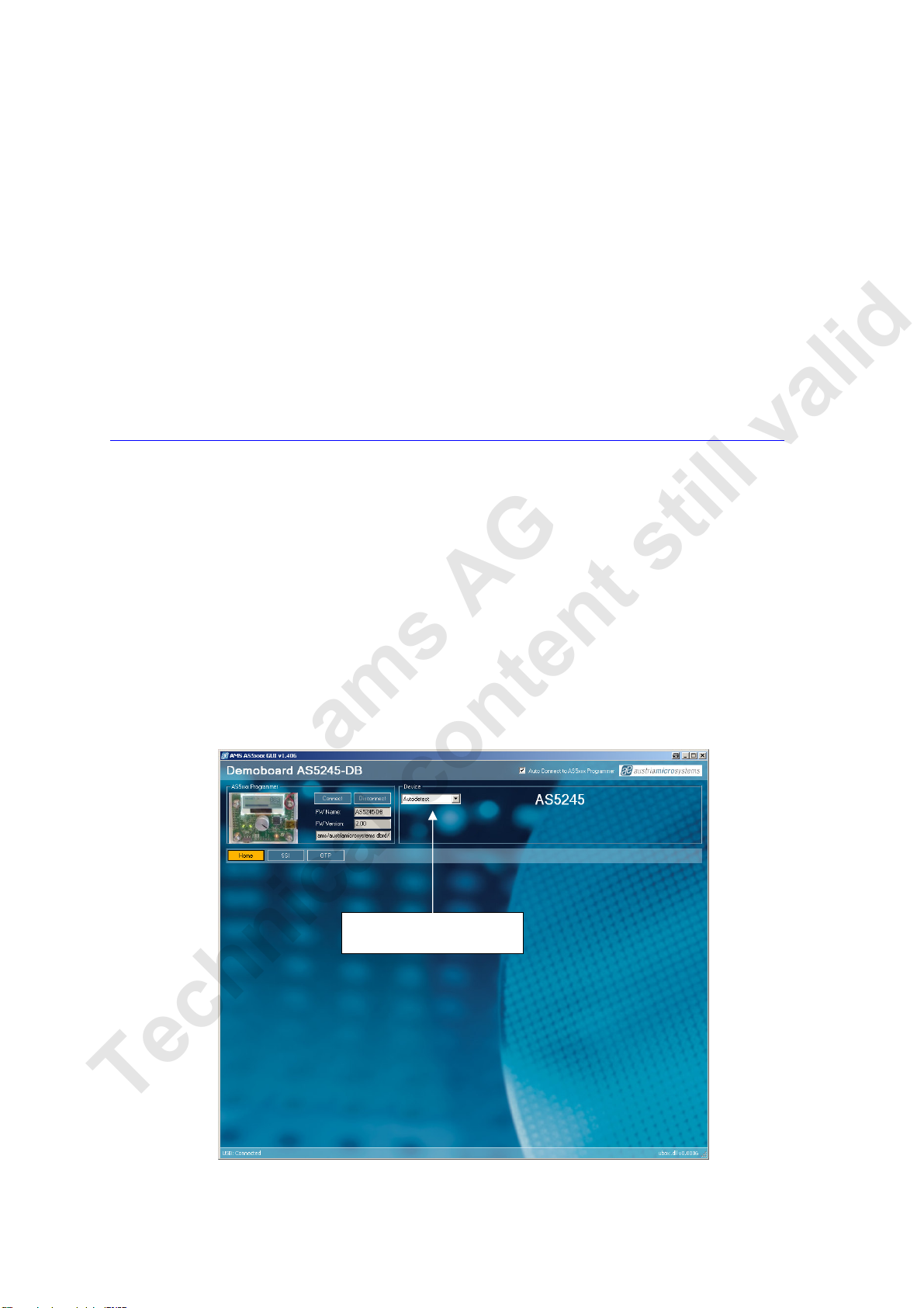
•As input device for the AS5000 GUI software
Connect the demoboard to a PC using a U B/U B cable (included in demoboard shipment). The board is supplied by
the 5V supply of the U B port. No other connections are required.
The LCD display will be turned off and the Angle/ tatus bits will be displayed on the PC screen (A 5000 GUI). ome
extra features as e.g. zero position programming can be achieved. The parameters will not be permanently
programmed. All the parameters will be lost when the demoboard is shut down. For a permanent device programming,
the “A 5000 Programmer” hardware should be used.
3.1 Hardware Indicators
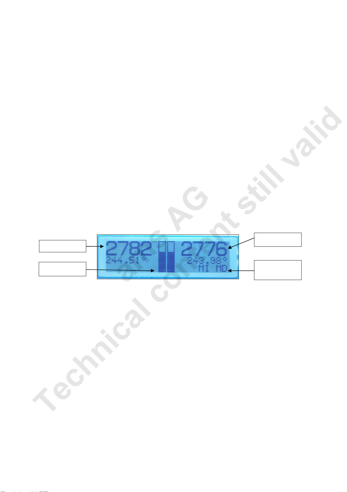
3.1.1 Graphic LCD display
The LCD display shows the realtime absolute angle position of the magnet with a resolution of 0.09° = 4096 positions
per revolution and the absolute value of the angle.
Turning the knob clockwise will increase the angle value until 359.9° (value 4095), then 0°.
The magnet status indicator is related to the magnet position. If the magnet is too close or too far away from the
encoder, “Magnet out of range” will be displayed.
Figure 2: LCD display in standalo ne mode (9V battery or USB power ed without GUI)
3.1.2 PWM LED
The PWM LED is connected to the PWM output of the A 5245. The PWM output is a pulse width that is proportional to
the angle of the magnet.
The pulse width varies from 1µs to 4096µs with a repetition rate of 244Hz. Viewing the PWM signal on the LED results
in brightness that is proportional to the angle of the magnet. When the angle of the magnet is at 0°, the LED is almost
dark, as it is 1µs on and 4095µs off. Turning the knob clockwise towards higher angles increases the brightness of the
PWM LED, since the ON-pulse becomes longer and the OFF-pulse becomes shorter.
Likewise, the PWM output can be used as an analog output proportional to the angle, when the PWM signal is filtered
by a RC (or active) lowpass filter.
The PWM signal (digital 0 ~ 3.3V) can be directly taken from the connector P1.
3.1.3 MagINc and MagDECn LED
MagINCn and MagDECn are the magnetic field change indicators (magnetic field strength increase or decrease through
variation of the distance between the magnet and the device).
These outputs can be used to detect the valid magnetic field range. If both indicators lit simultaneously
(MagINCn = 0 and MagDECn = 0), the magnet is out of range, the airgap between the encoder and the magnet is too
high or too low (see Figure 2).
Magnet indicator:
- Distance OK
- Magnet out of range
Magnet angle value
from
0° to 359.9°
degree
Absolut
e
angle
value
12 bit resolution: 0 to 4095
Bargraph representation of
the angle (0° to 359.9°)
ams AG
Technical content still valid

Revision 1.1, October-2009 Page 3 of 10
www.austriamicr osys tems.com
3.2 Encoder selection switch
The switch W1 selects the encoder which communicates with the microcontroller through the I bus:
1. Right position (default): Onboard A 5245
2. Left Position: External A 5245 on P2
The signals of the synchronous serial interface (DO, CLK, C n, PROG) and the power supply (3.3V,
GND) of an external device can be connected directly to P2. In this configuration, the data of the serial
interface are displayed on the GUI or the LCD.
4AS5000 Programmer GUI software
4.1 Installing the GUI on the PC
The preliminary software is developed for a Microsoft Windows XP operating system with ervice Pack 2. In addition
the dotnet (.NET) framework version 2.0 or more must be installed on the PC. This package can be downloaded free of
charge from the Microsoft webpage:
http://www.microsoft.com/downloads/details.aspx?FamilyID=0856eacb-4362-4b0d-8edd-aab15c5e04f5&displaylang=en
Following Procedure is recommended before starting the GUI:
1. check on your PC if ervice Pack 2 is installed
2. install the mentioned .NET package to your computer
3. execute setup.exe
4. Finally start the GUI using the shortcut in the start menu or desktop.
4.2 The Home tab
Figure 3 shows the main window of the GUI. On the top left corner, board information’s as firmware (FW) version and
demoboard name declaration can be found.
By default the GUI is in the auto detection mode. Any connected austriamicrosystems demoboard and programming tool will
be automatically detected and the device type is displayed in the right top corner of the main window. The GUI is divided into
three main sections HOME, I and OTP.
Figure 3: AS5000 GUI has detected th e AS 5245 Demoboard
Device selection list allows changing
the encoder type manually
ams AG
Technical content still valid

Revision 1.1, October-2009 Page 4 of 10
www.austriamicr osys tems.com
4.3 The SSI tab
By selecting the I (serial protocol for A 5040, A 5140, A 5043, A 5045, A 5145, A 5245) tab, the real time information
of the angular position and the status bits are displayed. ee figure 4.
Figure 4: SSI tab, shows the SSI bus data of the select ed encoder
Value is the Angle data [D11:D0] from the RD_ANGLE (Read Angle) serial command. This value is continuously
updated.
The Zero Pos. value represents the Zero Position register. By clicking on the et button, the actual angle
“Value” is written into the Zero Position register. Clicking on Reset writes the value 0 to the Zero Position register.
The Magnetic Range Warning is continuously read from the RD_ANGLE serial command.
•Green lamp: Magnet in range
•Orange lamp: Magnet too far or close. MagINC and MagDEC are set.
•Red lamp: Magnet too far or close, angle value is invalid and LIN bit is set.
The red lamp is available only when OTP MagCompEN=1, available from the OTP tab.
The Status bits information is taken from the serial stream.
The Read Interval can be modified from 10 ms (fastest) to 1 s (slowest).
Magnet angle value
0 to 359.9°
Magnet
range warning
:
- Green: magnet in Range
- Orange: magnet too close or too far
- Red: magnet to close or too far, data
invalid (if MagCompEN = 1 only)
Angle register value:
Zero position register access:
-
Button ET: ets the current angle
as the 0° angle
- Button RE ET: resets the Zero
Position register to 0 (default)
Angle value
:
12 bit absolute position: 0 to 4095
Die selection
(dual die
encoders
only)
tatus bits information
et counter clockwise
Display update rate. The readout speed can be
adjusted from 10ms to 1s
ams AG
Technical content still valid
Table of contents
Other AMS Media Converter manuals
Popular Media Converter manuals by other brands

H&B
H&B TX-100 Installation and instruction manual

Bolin Technology
Bolin Technology D Series user manual

IFM Electronic
IFM Electronic Efector 400 RN30 Series Device manual

GRASS VALLEY
GRASS VALLEY KUDOSPRO ULC2000 user manual

Linear Technology
Linear Technology DC1523A Demo Manual

Lika
Lika ROTAPULS I28 Series quick start guide

Weidmuller
Weidmuller IE-MC-VL Series Hardware installation guide

Optical Systems Design
Optical Systems Design OSD2139 Series Operator's manual

Tema Telecomunicazioni
Tema Telecomunicazioni AD615/S product manual

KTI Networks
KTI Networks KGC-352 Series installation guide

Gira
Gira 0588 Series operating instructions

Lika
Lika SFA-5000-FD user guide