PlaneWave CDK12.5 User manual

PlaneWave CDK Telescope Instructions
Setting the spacing and collimation for the CDK12.5/14/17/20/24

V20160909
1
Collimation and Secondary Spacing Procedure
The CDK optical design has four optical elements shown in Figure 1. The primary mirror
and the two-element lens group are permanently mounted and aligned at PlaneWave
Instruments. The secondary mirror is movable to allow fine collimation and to set the
spacing between the primary and secondary. To get the best performance out of the CDK
optical system, the optics must be collimated and the primary-to-secondary mirror spacing
must be set. Please note that the primary-to-secondary spacing is set at the factory and
typically does not need to be adjusted unless it was moved after shipping.
Figure 1: The optical layout of the CDK system. The system contains 4 elements: the primary mirror, the
secondary mirror, and a two-element lens group.
Step 1: Collimation / Spacing Adapters for the CDK 14/17/20/24
(For CDK 12.5 proceed to Step 1b below)
If your CDK came with the optional Hedrick focuser (200340) attached, You must first
remove the attached focuser before attaching the Ronchi Adapter and Spacer.
a. Use an Allen wrench and remove the three socket head bolts that holds the focuser
retaining ring. Make sure that you are holding the body of the focuser while removing
the screws
Focuser
Mounting
Screws
Focuser
Retaining
Ring
Figure 2 –Focuser and Retaining Ring

V20160909
2
b. Remove focuser from the back plate of the telescope.
c. Place the Ronchi Adapter in the back plate of the telescope and replace the focuser
retaining ring to hold the adapter in place. See Fig 4
Note: For packaging purposes the Ronchi Adapter may come in two pieces; the round mounting plate
and the adapter. There should be three 10-32 Flat head screws included to attach the two pieces.
d. Insert the Ronchi Spacer into the Ronchi Adapter and lock it down with the thumb
screw.
e. Place the barrel of a low power eyepiece (for collimation) or the Ronchi Ocular (for
spacing) into the Ronchi spacer and lock it down with the thumb screw.
Step 1b: Collimation / Spacing Adapters for the CDK12.5 only
1. For the CDK12.5 the included Ronchi adapter will be placed inside the barrel of the
focuser and locked down using the thumb screws.
2. The Ronchi Spacer is then inserted into the adapter and secured with the thumb
screws on the adapter.
3. Finally the Ronchi eyepiece is placed in spacer and secured with the spacer thumb
screw.
Fig3 –Adapters required for CDK14-24 telescope
Fig 4 –Ronchi Ocular, Spacer and Adapter

V20160909
3
Step 2: Rough Collimation:
To collimate your CDK you will need to have a low power, 1.25” eyepiece inserted into the
Ronchi Spacer.
a. Point the telescope at a bright star.
b. Defocus the star until it becomes a donut-like ring. If the donut hole appears well
centered in the donut, proceed to Step 3.
c. If the donut hole is not centered, adjust the collimating screws on the back of the
secondary mirror so that the defocused star moves in the direction of the fat side of
the donut, as shown in Figure 5. Re-center the star and repeat this process until the
donut hole looks centered as shown in Figure 6. See below for details on how to
adjust the collimating screws.
Figure 5: An example of what you would see through a low-power eyepiece for an out-of-focus, out-of-
collimation telescope. To collimate this telescope you would adjust the secondary collimating screws so that
the out-of-focus star moves in the direction of the arrow.
Ronchi Spacer
Ronchi Eyepiece
Ronchi Adapter
Adapter included with CDK12.5

V20160909
4
Figure 6: An example of an approximately collimated defocused star.
The CDK uses three ¼-20 socket head cap screws for collimation, as shown in Figure 7.
These screws require a 3/16 Allen wrench. It may be necessary to slightly loose the two
opposing screws in order to tighten the third screw. Remember to always finish tightening
with the secondary preloaded securely against all three screws.
Collimating is usually a two-person job: one person looks through the eyepiece while one
person adjusts the collimating screws. Attempting to do this alone can be quite difficult and
frustrating. If necessary, you might try using a webcam with a 1-1/4” nosepiece, such as the
Celestron NexImage, in place of an eyepiece. With this setup, you can watch the video
stream from the camera while you make adjustments.
Note that the central spacing knob is not used until Step 3.
.
Central Spacing Knob
Collimating screw
Figure 7: The CDK secondary housing. There are three
collimating screws and a central knob. The secondary on the
CDK is spring loaded, pulling the secondary into the three
collimating screws

V20160909
5
Step 3: Setting the Primary-to-Secondary Spacing:
The primary-to-secondary spacing is set at the factory. You will typically not need to adjust
this unless the secondary has been moved.
For your CDK optical system to perform as well as it should, the spacing between the
primary mirror and secondary mirror should be set to an accuracy of +/- 1mm! Fortunately,
you won’t have to directly measure this spacing. When the primary-to-secondary spacing is
set correctly, the focal plane will land at an exact known distance behind the fully racked in
focuser. The Ronchi Adapter and Spacer places the Ronchi grating of the Ronchi Ocular
precisely where the focal plane is supposed to be.
Collimation knobs
Central Secondary Spacing Bolt
For the CDK12.5 there are four collimation screws and a central
bolt used for spacing

V20160909
6
About the Ronchi Test
Figure 8 illustrates the basic idea behind
using a Ronchi grating to identify the
position of the focal plane. The light from a
single bright star passes through the optical
system and converges to a point on the
focal plane. When the Ronchi grating is
placed in front of or behind the focal plane,
it will block some of the light in this light
cone. This will cast a series of shadows that
appear as dark, wide lines when the
defocused light is viewed through the
ocular.
As the grating moves closer to the focal plane, fewer lines are visible, and they become
wider. When the focal plane and the Ronchi grating are perfectly aligned, no lines (or
perhaps one very wide line) are visible. See Figure 9 for an example.
In order to set the primary-to-secondary distance, you will be moving the secondary mirror.
By adjusting secondary mirror distance, you will be moving the focal plane relative to the
fixed position of the Ronchi grating. The job here is to move the secondary mirror such that
the focal plane coincides with the Ronchi grating on the Ronchi Ocular. When you have
done this, you have accurately set the primary-to-secondary spacing.
With reasonable effort, the primary-to-secondary spacing can be set to well within its 1mm
tolerance.
Figure 8: The Ronchi grating casts fewer shadows as
it moves closer to the focal plane.

V20160909
7
Figure 9: The left image is a simulation of what a focused star looks like through a Ronchi grating. The right
image is a simulation of what an out of focus view looks like through a Ronchi grating. The right image shows
2 full lines. The more lines you see, the farther the Ronchi screen is from the focal plane.
Step 4: Setting Up the Test
Starting with a telescope that is fairly well collimated, center a bright star and replace the low
power eyepiece with the Ronchi Ocular that was provided with the telescope. Make sure the
Ocular is seated all the way into the adapter. If the Ronchi is nulled (you can see no lines, or
one Ronchi line covers the entire aperture; see Figure 9) This means that your spacing is
already set; you may proceed to Step 4. This is not uncommon because the primary-to-
secondary spacing is set at PlaneWave and you most likely will not need to adjust it.
If you see two or more lines, you should move the secondary toward or away from the
primary.
Determining the Direction to Move the Secondary
To determine which way to move the secondary, gently slide the Ronchi Ocular out of the
spacing tube. If the Ronchi reaches null as you do this, the focal plane is too far back and
you need to move the secondary mirror away from the primary. If the number of lines grows
as you slide the Ronchi out of the spacing tube, the focal plane is too far forward and you
need to move the secondary toward the primary.
Remember that the secondary mirror acts as a magnifier. So a small change in secondary
spacing can translate into a much larger change at the focal plane. For example, for every
1mm the secondary spacing is changed on the CDK17, the focal plane moves 4.4mm. You
want to keep the error at the focal plane to 5mm or better, which equals just under two lines
on the Ronchi. This corresponds to an error in primary-to-secondary spacing of about +/-
1.1mm. See table below for spacing tolerance for all CDK models.

V20160909
8
CDK
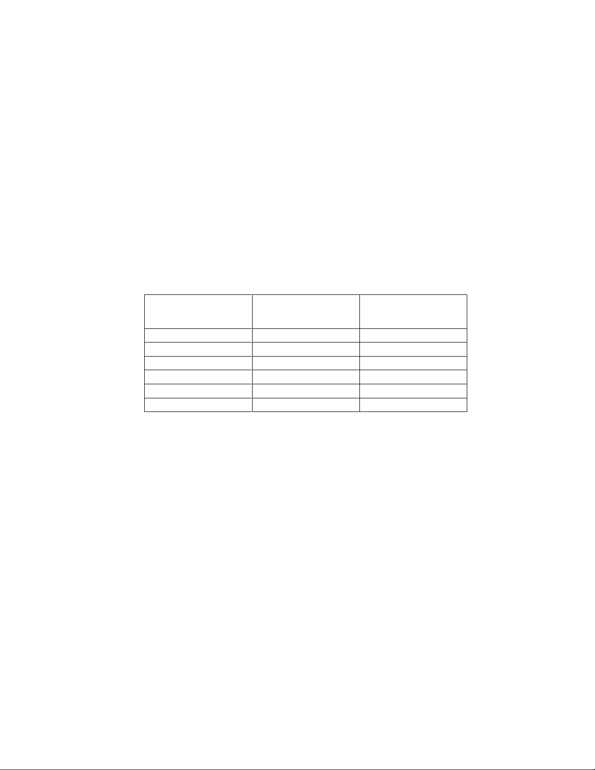
Focal plane change for
every 1mm of secondary
spacing change
Allowable primary-to-secondary
spacing tolerance to keep focal
plane within 5mm of optimal
12.5
7.5mm
+/- .7mm
14
4.9mm
+/- 1.0mm
17
4.4mm
+/- 1.1mm
20
5.1mm
+/- 1.0mm
24
4.1mm
+/- 1.2mm
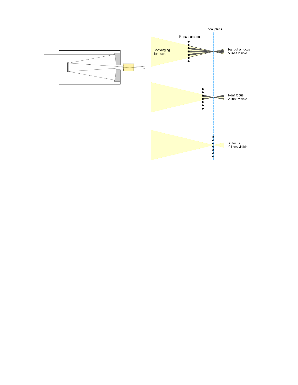
Figure 9 shows a Ronchi simulation with the Ronchi screen set at the focal plane and also
with the focal plane 10mm away from the Ronchi screen. The image on the left is what you
will see if the primary-to-secondary spacing is perfect. The image on the right is what you
will see if the primary-to-secondary spacing is off by about 2mm. Remember, you want
better than 1mm spacing accuracy for the CDK17.
Adjusting the Secondary Spacing
The CDK secondary mirror is not spring loaded, so you must always keep tension in the
collimating screws and the central bolt. To move the secondary toward the primary mirror:
1. Loosen three screws (four screws for the CDK12.5) . Loosen them in equal amounts
to maintain your collimation.
2. Hold the secondary housing with one hand. This is to keep the housing from rotating.
(The collimation screws sit in shallow recesses and you would like them to go back in
the recesses when the procedure is complete).
3. Take a flat-head screwdriver and place the tip in the central bolt of the secondary
assembly. Rotate the central bolt in a clockwise direction. For reference, rotating
¼ turn moves the secondary .4mm, which moves the focal plane 1.76mm in the
case of the CDK17.
4. Turn the collimation knobs in equal amounts until the assembly is tight again.
5. Check the Ronchi grating and repeat this process as necessary until you get a null.
To move the secondary away from the primary:
1. Loosen the collimation screws. Loosen them in equal amounts to maintain your
collimation.
2. Hold the secondary housing with one hand. This is to keep the housing from rotating.
(The collimation screws sit in shallow recesses and you would like them to go back in
the recesses when the procedure is complete).
3. Take a flat-head screwdriver and place the tip in the central bolt of the secondary
assembly. Rotate the central bolt in a counter-clockwise direction. For reference,
rotating ¼ turn moves the secondary .4mm, which moves the focal plane 1.76mm
in the case of the CDK17.
4. Rotate the four collimation knobs in equal amounts until the assembly is tight again.
5. Check the Ronchi screen and repeat this process as necessary until you get a null.
Re-checking Collimation
After you are satisfied that the secondary spacing is correct, replace the Ronchi ocular with
the low power eyepiece and repeat step 1 to verify that the collimation is still close. If re-
collimation adjustments are necessary, make them and repeat step 3.

V20160909
9
Step 4: Fine Collimation:
Use a high-power eyepiece (5mm or less) and follow the same procedure described in Step 1
(adjust the secondary so that the donut hole is in the center of the donut). You may want to
switch to a low-power eyepiece while making adjustments and re-centering the star, and back
to high power to check the collimation.
Finally, use the Ronchi Ocular to re-check the spacing. As long as only small adjustments
were made in Step 3, the spacing should still be fine. If it is not, repeat Step 2 and Step 3.
Back Focus
The CDK design does not have any moving optical components, so the focal point is fixed.
This means that the focal plane of the telescope is a set distance behind the backplate of the
telescope. The back focus for the various telescope models in shown in Table 1 below.
Backfocus from
mounting surface of
telescope backplate
Back focus from fully
racked in focuser
CDK12.5
10.45”
7.2”
CDK14
11.09”
8.09”
CDK17
10.24”
7.24”
CDK20
8.81”
5.81”
CDK24
*14.1”
5.81”
CDK700
**12”
8.5”
Table 1: Shows the back focus with and without the focuser installed for the various PlaneWave telescope
models.
*CDK24 can also use optional spacers to increase back focus to be the same as the CDK17 or CDK14.
**The CDK700 is referenced, not from the backplate of the telescope, but from the end of the altitude hub
which is the mounting surface for the optical train. Also, the CDK700 is using the Focuser/Rotator 600180,
which uses 3.5” of backfocus on the CDK700.

V20160909
10
Mounting SecureFit Spacers to the Hedrick Motorized Focuser
1. The face plate of the focuser (200340) has four threaded holes that should be used to
mount any of Planewave’s SecureFit adapter. Use the ¼-20 screws provided with
your SecureFit adapter to mount it on the face of the focuser.
2. The remaining four holes has screws that hold the face plate to the body of the
focuser and should not be removed.
3. There are also a series of set screws that are used to level the face plate relative to the
image plane. These set screws should not be removed or loosened in any way.
1) SecureFit
Mounting Screws
2) Face Plate
Attachment Screws
3) Face Plate Leveling
Screws
This manual suits for next models
5
Table of contents
Other PlaneWave Telescope manuals