Pluggit AeroFresh Plus User manual

Operating and installation instructions
Manuel d‘utilisation et d‘installation
www.pluggit.com
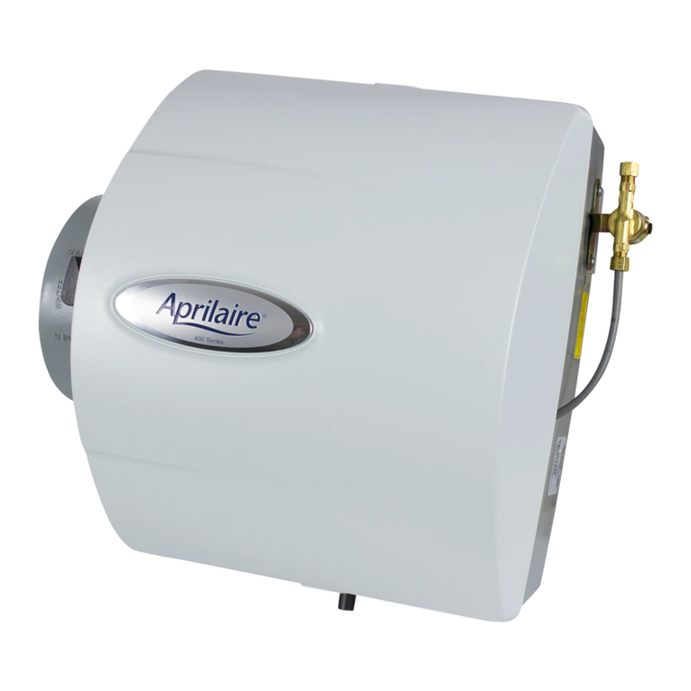
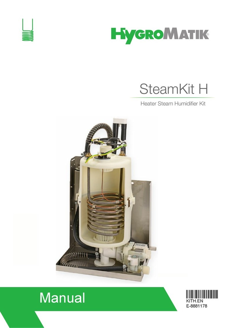
AeroFresh Plus air humidifier
Humidificateurs d’air AeroFresh Plus

The technology makes the difference.
Pluggit's value-added innovations for man and the environment.
Appetite for fresh air? You can get more information on the company,
the intelligent technology of Pluggit comfort ventilation systems,
references and regional contacts at
www.pluggit.com or as an on-line dialogue at www.lueftungsblog.de
The air conduct being installed invisibly in the floor and an ideal
positioning of the air outlets make for perfectly aligned transverse
ventilation. Displacement ventilation means that the fresh air is
supplied to the room almost without causing any draughts and
disturbing noise, without pressure and preheated during the
cold months.
Fresh air and heat supply in one - quicker, more flexible and more
energy saving than common heating systems.
allfloor – in ceilings, walls, above or under concrete and screed -
the Pluggit system design offers maximum flexibility with regard to
the installation of the ventilation ducts and thus is ideal for the use
in new buildings as well as for the refurbishment of
existing buildings.
This innovative technology allows for the supply of exactly the
required or desired amount of fresh air thanks to a highly sensitive
sensor system and control. Cost and time saving, the unit adapts to
the system characteristics at the touch of a button after the
installation and automatically calibrates itself consistently at
regular intervals.
Energy efficiency - a high heat supply rate alone makes a ventilation
system seem effective and energy efficient only at first glance.
The decisive factor for an assessment is rather the ratio of the
energy spent to the attained heat recovery rate - the so-called
electrical energy efficiency. Due to a high tightness, a consumption-
optimised device design and the latest heat exchanger technology,
our ventilation systems attain excellent ratings in terms of heat
recovery and energy efficiency.
The CleanSafe principle guarantees a very low pollution potential of
our distribution system due to smooth surfaces and a trouble-free
cleaning concept, the convincing results of which have been
confirmed by an independent testing institute.
Appetite for fresh air in your building?
The unique comfort ventilation system for the energetic
refurbishment of existing buildings.
2Q
allfloor
ServoFlow
CleanSafe

1
BIA AeroFresh Plus
1. General safety information ................................................................................................. 5
2. General notes ...................................................................................................................... 5
2.1. Intended use ........................................................................................................................ 5
2.2. Unintended use .................................................................................................................... 5
2.3. Warranty .............................................................................................................................. 5
2.4. Functioning/operating principle .......................................................................................... 5
3. Installation (expert personnel) ........................................................................................... 6
3.1. Overview .............................................................................................................................. 6
3.2. Notes on the installation ..................................................................................................... 7
3.2.1. Overview installation ................................................................................................. 8
3.3. Safety function ..................................................................................................................... 9
3.4. Remote indication (optional) ............................................................................................... 9
3.5. Installing humidifier ............................................................................................................ 9
3.6. Install humidifying line ........................................................................................................ 9
3.7. Connecting humidifier ....................................................................................................... 11
3.7.1. Feeding steam hose and condensate line ............................................................... 13
3.8. Electrical connection ......................................................................................................... 13
3.8.1. Connect humidifier .................................................................................................. 13
3.8.2. Connect control signals ........................................................................................... 13
3.8.3. Relay for external signals ....................................................................................... 13
3.8.4. Connecting terminals .............................................................................................. 14
3.8.5. Circuit diagram hygrothermal transducer 0-10 V .................................................. 14
3.8.6. Circuit diagram hygrothermal transducer 4-20 mA ............................................... 14
4. Commissioning (expert personnel) .................................................................................... 14
5. Operation ........................................................................................................................... 15
5.1. Control unit ........................................................................................................................ 15
5.2. Programmes ...................................................................................................................... 15
5.2.1. "Service" programme .............................................................................................. 15
5.2.2. "Adjustments" programme ..................................................................................... 16
5.2.3. "Controller" programme ......................................................................................... 17
5.2.4. "Drain" programme ................................................................................................. 17
TABLE OF CONTENTS

2BIA AeroFresh Plus
5.2.5. "Count" programme ................................................................................................ 18
5.2.6. "Reset" programme ................................................................................................. 18
5.2.7. "Information" programme ....................................................................................... 18
6. Maintenance (user) ............................................................................................................ 18
6.1. Regular maintenance work ............................................................................................... 18
6.2. System and maintenance messages ................................................................................. 19
7. Maintenance (expert personnel) ........................................................................................ 20
7.1. Cleaning/replacing the steam cylinder ............................................................................. 20
8. Technical data .................................................................................................................... 22
8.1. Device data ......................................................................................................................... 22
8.2. Serial number .................................................................................................................... 22
8.3. Dimensions ........................................................................................................................ 22
9. Decommissioning/disposal ................................................................................................ 23
9.1. Decommissioning in case of dismantling ......................................................................... 23
9.2. Packaging ........................................................................................................................... 23
9.3. Old appliance ..................................................................................................................... 23
10. EU Declaration of Conformity ............................................................................................ 24

3
BIA AeroFresh Plus
1. Consignes générales de sécurité ....................................................................................... 27
2. Consignes générales .......................................................................................................... 27
2.1. Utilisation non conforme ................................................................................................... 27
2.2. Utilisation non conforme ................................................................................................... 27
2.3. Garantie ............................................................................................................................. 27
2.4. Fonction / principe ............................................................................................................. 27
3. Installation (personnel spécialisé) ..................................................................................... 28
3.1. Aperçu ................................................................................................................................ 28
3.2. Remarques relatives à l'installation ................................................................................. 29
3.2.1. Aperçu de l'installation ........................................................................................... 30
3.3. Fonction de sécurité .......................................................................................................... 31
3.4. Transmission à distance (disponible en option) ............................................................... 31
3.5. Installation de l'humidificateur d'air ................................................................................. 31
3.6. Installer la distance d'humidification ............................................................................... 31
3.7. Raccorder l'humidificateur d'air ....................................................................................... 33
3.7.1. Passage du tuyau à vapeur et de la conduite de condensat ................................... 35
3.8. Raccordement électrique .................................................................................................. 35
3.8.1. Raccorder l'humidificateur d'air ............................................................................. 35
3.8.2. Raccorder les signaux de commande ..................................................................... 35
3.8.3. Relais pour messages externes .............................................................................. 35
3.8.4. Borne de raccordement .......................................................................................... 36
3.8.5. Schéma électrique de la sonde hygrothermique 0-10 V ........................................ 36
3.8.6. Schéma électrique de la sonde hygrothermique 4-20 mA...................................... 36
4. Mises en service (personnel spécialisé) ............................................................................. 36
5. Commande ......................................................................................................................... 37
5.1. Unité de commande .......................................................................................................... 37
5.2. Programmes ...................................................................................................................... 37
5.2.1. Programme " Service " ............................................................................................ 37
5.2.2. Programme " Adjustments " ................................................................................... 38
5.2.3. Programme " Controller " ....................................................................................... 39
5.2.4. Programme " Drain " ............................................................................................... 39
SOMMAIRE

4BIA AeroFresh Plus
5.2.5. Programme " Count " .............................................................................................. 40
5.2.6. Programme " Reset " ............................................................................................... 40
5.2.7. Programme " Informations " ................................................................................... 40
6. Maintenance (utilisateur) .................................................................................................. 40
6.1. Travaux de maintenance réguliers .................................................................................... 40
6.2. Messages du système et de maintenance ........................................................................ 41
7. Maintenance (personnel spécialisé) .................................................................................. 42
7.1. Nettoyage / Remplacement du cylindre à vapeur ............................................................. 42
8. Données techniques .......................................................................................................... 44
8.1. Données relatives à l'appareil ........................................................................................... 44
8.2. Numéro de série ................................................................................................................ 44
8.3. Dimensions ........................................................................................................................ 44
9. Mise hors service / Élimination ......................................................................................... 45
9.1. Mise hors service lors du démontage ............................................................................... 45
9.2. Emballage .......................................................................................................................... 45
9.3. Appareil usagé ................................................................................................................... 45
10. Déclaration CE de conformité ............................................................................................ 46

5
BIA AeroFresh Plus
English
2.1. INTENDED USE
The humidifier serves to increase the humidity in the room
air by means of water vapour. For this purpose water from
the existing drinking water system is fed into the humidifier.
2.2. UNINTENDED USE
Any use other than that described in "Intended use" shall
not be permissible.
Do not install the humidifier outside due to the risk of frost
and rain.
Temperatures must not exceed 40 °C where the humidifier
is placed.
Do not install the humidifier next to or above devices sensi-
tive to water.
2.3. WARRANTY
In order to preserve your full statutory warranty claim, the
technical guidelines in these operating and installation in-
structions must be observed.
Only original Pluggit components and original Pluggit spare
parts must be used.
2.4. FUNCTIONING/OPERATING PRINCIPLE
The water is converted to water vapour in a steam cylinder
with electrode heating. For this purpose the water is in-
serted through an inlet valve and a filling system in the
steam cylinder. When the electrodes come into contact with
the water, they cause an electric current to flow. The water
is heated up until it evaporates.
The evaporation takes place at very low pressure.
Water is inserted in the steam cylinder until the required
steam output is reached. Subsequently, the inlet valve will
automatically close.
When the minimum current level is reached, the inlet valve
will open and water will again be inserted in the steam cyl-
inder.
Due to the evaporation, the conductivity of the water in the
steam cylinder increases. Perfect adaptation to the indi-
vidual quality of the used water and the required steam
output is carried out fully automatically.
Thanks to this auto-tuning of the optimal water concentra-
tion in the steam cylinder, a change in the steam output can
be reached by means of even minimal variations of the
water level.
Pluggit recommends that you check the flow-calming sec-
tion during the humidifying season.
1. GENERAL SAFETY INFORMATION
Warning:
The following safety instructions must be observed,
since damage and injury may otherwise result:
zPlease read these installation instructions care-
fully before installing, operating and maintaining
the unit.
zThe installation and all electrical work must only
be carried out by qualified expert personnel.
zWhen installing and commissioning the humidi-
fier, observe all necessary legal and national re-
quirements (accident prevention regulations and
generally accepted codes of practice) and comply
with them.
zThe local rules concerning the connection of de-
vices to the pressure and wastewater system
must be observed.
zDo not start running the humidifier before all in-
stallation work is completed.
zWhen operating the humidifier, all covers must
be closed.
zDo not place combustible liquids or inflammable
material in immediate proximity to the humidi-
fier while it is running.
zDamages resulting from inappropriate storage
of the product, improper installation and han-
dling, insufficient maintenance or unintended
use are excluded from any liability.
zTechnical changes reserved.
2. GENERAL NOTES
Note:
It is not recommended that you use chemically treated
water or water from water softening and desalination
plants.
Note:
In case of information provided by the local water utility
company on, e.g. environmental pollution of the water,
the humidifier must be switched off.

6BIA AeroFresh Plus
3.1. OVERVIEW
Humidifier basic set BF5
1Humidifier AeroFresh Plus
2Control electronics
3Control unit
4Steam cylinder
5Filling system
6Steam hose
7Water inlet valve
8Water outlet valve
9Drain
10 Condensate line humidifying line
11 Water supply pipe
12 Water drain pipe
13 Electrical connection
Humidifying line BF5-BS
14 Humidifying line
Security set BF5-FS (sensor set)
15 Hygrostat (max. humidity limiter)
16 Hygrothermal transducer (humidity sensor actual value
indication)
Components provided by the customer
17 Supply air line
18 Exhaust air line
19 Stopcock or angle valve (1/2")
3. INSTALLATION (EXPERT PERSONNEL)
14
6
17
19
18
17
15
13
1
10
3
2
4
8
9
5
7
12
11
16
M+P-26A-1010

7
BIA AeroFresh Plus
English
3.2. NOTES ON THE INSTALLATION
• Choosing the right place for the humidifier:
•Vibration-free.
• Water-protected.
• Free from temperature fluctuations.
• Near the humidifying line.
• As close as possible to the room ventilation unit.
• Water and wastewater connection available.
• Before installing the humidifier, take the distances to
ceiling, ducts and wall into account in order to provide
for any additional material if necessary.
• The humidifier must be freely accessible for all mainte-
nance work.
• The humidifier and the humidifying line must be fixed to
a bearing wall or ceiling respectively.
When fixing the humidifier to plasterboard, appropriate
fixing material must be used.
• The humidifying line must be installed horizontally.
• Connect the humidifier using the shortest possible
steam hose (1.5 m) and few bows to the humidifying line.
Shorten steam hose if necessary. A 5-meter steam hose
is available as an option.
• Protect the steam hose against external influences such
as bending and deformation.
• Avoid condensate pockets in the steam hose.
• Install an aquastop (not included in delivery) as safety
device.
• If no fine filter is installed at the water meter, Pluggit
recommends that you install one before installing the
humidifier.
• Install a funnel or siphon for the discharge of conden-
sate and blowdown water. When the condensate is dis-
charged into a funnel, a minimum slope of 5 % must be
observed.
• The water pressure in the line for the water supply must
be 1-10 bar. When it is above 10 bar a pressure reducing
valve must be installed and set to 4 bar.

8BIA AeroFresh Plus
3.2.1. Overview installation
1Room ventilation unit
2Humidifier AeroFresh Plus
3Humidifying line
4Outside air line
5Supply air line
6Exhaust air line
7Outgoing air line
3
2
7
5
64
1
M+P-26A-1011

9
BIA AeroFresh Plus
English
3.3. SAFETY FUNCTION
The humidifier is protected against dry running. The current
flow automatically stops as soon as the electrodes in the
Should the current consumption significantly exceed the
nominal value (+ 25 %), the inlet valve will automatically
open. Since the immersion depth of the electrodes in the
water is consequently reduced, the current consumption
falls back to the nominal value.
Should the current consumption, even after repeated
draining of the water, still exceed 140 % of the nominal cur-
rent, the humidifier will automatically switch off after a
short period of time.
3.4. REMOTE INDICATION (OPTIONAL)
Thanks to an additional board with floating relay output,
system messages can be displayed on a central building
control system (BCS).
3.5. INSTALLING HUMIDIFIER
1. Drill holes as shown here.
Aapprox. 100 mm
Bapprox. 400 mm
C100 mm
D355 mm
Eapprox. 400 mm
2. Screw the screws (1) in.
3. Fit humidifier (2).
3.6. INSTALL HUMIDIFYING LINE
1. Drill holes according to the location planning to fasten
the humidifying line (1).
2. Tighten humidifying line (1) with clamps (2).
C
E
B
A
D
1
12
M+P-26A-1012
Note:
Choose screws (1) with fitting dowels in accordance with
the masonry.
Note:
Choose screws with fitting dowels in accordance with
the masonry.
2
1
2
M+P-26A-1013

10 BIA AeroFresh Plus
3. Insert hygrostat (3) in humidifying line (1).
4. Set absolute humidity using the rotary knob (4).
5. Connect supply air lines (5) to humidifying line (1) made
of IsoPlugg insulating duct or PluggFlex hose.
If you use a PluggFlex hose, secure it using hose
clamps (6).
6. Place hygrothermal transducer (7) in exhaust air line (8)
and secure it using holder (9).
6
3
1
6
59 7
8
8
5
4
M+P-26A-1014
Note:
Pluggit recommends that you set the absolute humidity
to 80 % to ensure a higher degree of safety.

11
BIA AeroFresh Plus
English
3.7. CONNECTING HUMIDIFIER
1Humidifier AeroFresh Plus
2Water supply pipe
3Fine filter if necessary
4Stopcock or angle valve
5Water drain pipe
6Funnel or siphon
1. Install water supply pipe (2) and water drain pipe (5) as
shown here and secure lines using pipe or hose clamps.
2. Position steam cylinder (7) on steam cylinder (8) and se-
cure it using hose clamp (9).
Warning:
The water drain pipe (5) must withstand a tempera-
ture of 100 °C, otherwise injury and damage may
result.
Electrically conductive pipes must be properly
earthed.
Note:
Pluggit recommends that you choose a water supply
pipe (2) made of copper or iron. Pipes made of plastic
may cause the formation of foam inside the steam cyl-
inder.
4 2
1
3
5
6
M+P-26A-1015
Note:
A hose with an interior diameter of 21 mm should be
used for the water drain pipe (5). The hose must not
come into contact with the funnel or the siphon (6). A
minimum distance of 25 mm must be observed.
Warning:
Only an original Pluggit steam hose must be used.
The steam hose (7) must not be thermally insu-
lated.
Note:
If the steam hose (7) is installed next to other objects,
these objects must withstand temperatures of 100 °C.
7
6
7
19
8
M+P-26A-1016

12 BIA AeroFresh Plus
3. Connect hygrostat (10) and hygrothermal transducer
(11) according to circuit diagram, see page 14.
4. Fasten steam hose (7) to humidifying line (12) and se-
cure it using a hose clamp.
5. Insert condensate line (13) in humidifying line (12) and
clip in a funnel or a siphon (14) using a siphon loop.
6. Connect humidifier (1) to the power supply system.
7. Fully open stopcock or angle valve (4).
12
7
4
10
14
1
13
11
M+P-26A-1017
Note:
Take care to correctly guide the steam hose (7) and the
condensate line (13), see page 13.

13
BIA AeroFresh Plus
English
3.7.1. Feeding steam hose and condensate line
To prevent the steam from flowing back in the condensate
line of the humidifying line, the latter must be installed
using a siphon loop.
1Humidifier AeroFresh Plus
2Humidifying line
3Steam hose
4Condensate line humidifying line
5Funnel or siphon respectively
1. Feed the steam hose (3) and the condensate line (4) with
gradients of at least 20 % to the humidifier (1).
2. Feed the condensate lines (4) using a siphon loop to the
funnel (5).
3.8. ELECTRICAL CONNECTION
3.8.1. Connect humidifier
Connect the Schuko plug of the humidifier to the on-site
socket.
3.8.2. Connect control signals
The humidifier is constantly controlled by a signal from the
internal humidity controller.
Connection external hygrothermal transducer (humidity
sensor)
Set controller signal from the hygrothermal transducer in
the programme AdJ, see page 16.
The following signals can be programmed:
Connection internal humidity controller
The humidifier already is factory configured for operation.
The relative humidity is set to 40 %.
The settings may be changed if required, see 15 et seq.
3.8.3. Relay for external signals
Connect the relay contact to terminals 9 and 10.
Note:
The distance (A) must be of at least 300 mm.
A
2
3
4
1
5
M+P-26A-1018
Risk of injury:
All electrical work must only be carried out by
qualified expert personnel.
Improperly or unprofessionally executed connec-
tions may otherwise cause burns or overheating.
All pipes must be copper pipes.
Tension 0-10 V
Current 4-20 mA
Note:
The internal humidity controller is switched on as de-
fault.
Note:
Do not connect to power supply above 24 V AC.

14 BIA AeroFresh Plus
3.8.4. Connecting terminals
The electronics are fitted with screw terminals for
max. 1.5 mm².
The number mark of the terminals is visible at the edge of
the printed circuit board. Number one starts on the left-
hand side.
3.8.5. Circuit diagram hygrothermal transducer 0-10 V
3.8.6. Circuit diagram hygrothermal
transducer 4-20 mA
• If the display of the control unit shows E4, the control
electronics are not encoded.
The humidifier can not be put into operation.
• Check all lines for leakages after commissioning.
• Hand the unit over to the user and inform about the han-
dling and the possible settings.
14-1
15-4
2
M+P-26A-1027
4. COMMISSIONING (EXPERT PERSONNEL)
Note:
Keep the commissioning protocol with the documents
relating to the system.
14-1
15-4
2
M+P-26A-1028

15
BIA AeroFresh Plus
English
5.1. CONTROL UNIT
1On/off switch
2Display
3LED corresponding to the SELECT button
The LED flashes when the SELECT button must be
pressed.
4SELECT button
You can choose between different functions in a pro-
gramme.
5LED corresponding to the SET button
The LED flashes when the SET button must be pressed.
6SET button
Values can be set.
7DIP switch
The DIP switches are already correctly set as default and
must not be moved.
8MODE button
• Manually rinse steam cylinder
• Start programmes
5.2. PROGRAMMES
The following programmes can be started using the MODE
button:
•dISP (display)
Basic function of the display.
•SEr (service)
Functions for the service.
•AdJ (Adjustments)
Set parameters.
•CtrL (controller)
Enable internal humidity controller.
Set parameters.
•drA (drain)
Set special drain functions.
•Coun (count)
Display operating hours.
•rSt (reset)
Reset settings to factory settings.
•inFo (information)
Display software version.
5.2.1. "Service" programme
The following functions can be started using the SEr pro-
gramme:
• Display water level in the steam cylinder.
• Display steam request.
• Effective heating current in amperes.
• Manually confirm the components of the humidifier for a
service check.
1. Repeatedly press MODE button until the display shows
SEr.
2. Press SELECT button.
SE.on is displayed when the maximum water level is
reached.
SE.oF is displayed when the maximum water level is
not yet reached.
3. Press SELECT button.
H on is displayed when steam has been requested.
H oF displayed when no steam has been requested.
4. Press SELECT button.
0000 displays the effective heating current in amperes.
5. OPERATION
Note:
The entire operation of the control system must only be
carried out by qualified expert personnel.
The user can set the humidity set points in the pro-
gramme CtrL if necessary, see page 17.
43 6 75
8
1
2
M+P-26A-1019
Note:
The display is already set to 40 % for the relative hu-
midity as default.

16 BIA AeroFresh Plus
5. Press SELECT button.
ChEC is displayed. The LED corresponding to the SE-
LECT button and the LED corresponding to SET button
flash.
6. Press SELECT button when the individual components
are not to be manually confirmed.
The SEr programme restarts
7. Press SET button when the individual components of the
humidifier are to be manually confirmed.
8. Press SELECT button.
Pis displayed.
9. Press SET button. The humidifier can be switched on or
off.
on --> switch on humidifier
oF --> switch off humidifier
10. Press SELECT button.
In is displayed.
11. Press SET button. The water inlet valve can be opened or
closed.
on --> open water inlet valve
oF --> close water inlet valve
12. Press SELECT button.
dr is displayed.
13. Press SET button. The water outlet valve can be opened
or closed.
on --> open water outlet valve
oF --> close water outlet valve
14. Press SELECT button.
Co is displayed.
15. Press SET button. The contactor can be switched on or
off.
on --> switch on contactor
oF --> switch off contactor
16. Press SELECT button.
rEL is displayed.
17. Press SET button. The signal relay can be switched on or
off.
on --> switch on signal relay
oF --> switch off signal relay
18. Press SELECT button.
The SEr programme restarts.
19. Press MODE button.
The SEr programme is terminated.
5.2.2. "Adjustments" programme
The following features can be set in the AdJ programme:
• Set steam output.
• Set controller signal of the hygrothermal transducer.
• Set switching-on threshold.
1. Repeatedly press MODE button until the display shows
AdJ.
2. Press SELECT button.
OL is displayed.
3. Press SET button. The steam output can now be set.
Setting range: 25oo-100oo
It is set to 100 % as default.
4. Press SELECT button.
CS is displayed.
5. Press SET button. The controller signal of the hygro-
thermal transducer can be set.
Setting range V: on.oF; 0-20; 0-16; 0-10
Setting range mA: i0.20; i4.20
4.20 is set as default.
6. Press SELECT button.
tP is displayed.
7. Press SET button. The switching-on threshold can be
set.
Setting range: 10oo-20oo
It is set to 20 % as default.
8. Press SELECT button.
The next programme is started.

17
BIA AeroFresh Plus
English
5.2.3. "Controller" programme
The following functions can be set in the CtrL programme:
• Switching on or off the internal humidity controller.
• Setting the humidity set points.
• Setting the parameters of the humidity controller (pro-
portional band and reset time).
1. Repeatedly press MODE button until the display shows
CtrL.
2. Press SET button. The internal humidity controller can
be switched on or off.
on --> switch on humidity controller
oF --> switch off humidity controller
3. Press SELECT button.
HuSP is displayed.
4. Press SET button. The humidity set points can now be
set.
Setting range: 10oo-99oo
(alternating display HuSP and value)
It is set to 40 % as default.
5. Press SELECT button.
Pr is displayed.
6. Press SET button. You can now change the proportional
band.
Setting range: 5-15
(alternating display Pr and value)
It is set to 10 as default.
7. Press SELECT button.
Int is displayed.
8. Press SET button. You can now change the reset time.
Setting range: 0-100
(alternating display Int and value)
It is set to 0 as default.
9. Press SELECT button.
The CtrL programme restarts.
10. Press MODE button.
The CtrL programme is terminated.
5.2.4. "Drain" programme
The following features can be set in the drA programme:
• Setting the drain volumen.
• Draining process under tension.
• Switching on or off regular draining of the steam cyl-
inder.
1. Repeatedly press MODE button until the display shows
drA.
2. Press SELECT button.
d.PLu is displayed.
3. Press SET button. An additional drain volume can be set.
Setting range: 0-99 seconds
(alternating display d.PLu and value)
It is set to 0 as default.
4. Press SELECT button.
d.Con is displayed.
5. Press SET button. The feature draining process under
tension can be switched on or off.
on --> switch on function
oF --> switch off function
The feature is switched off as default.
6. Press SELECT button.
d.Add is displayed.
7. Press SET button. The draining of the steam cylinder can
be switched on or off.
on --> Fswitch on feature. The steam cylinder is drained
every hour.
oF --> switch off feature
The feature is switched off as default.
8. Press SELECT button.
The drA programme restarts.
9. MODE-Taste drücken.
The drA programme is terminated.

18 BIA AeroFresh Plus
5.2.5. "Count" programme
In the Coun programme the operating hours of the humidi-
fier can be displayed
Repeatedly press MODE button until the display shows
Coun. The alternating display shows Coun and the value.
5.2.6. "Reset" programme
In the rSt programme all functions can be reset to factory
settings.
1. Repeatedly press MODE button until the display shows
rSt.
2. Press SET button.
All settings are reset.
5.2.7. "Information" programme
In the programme inFo the software version is displayed.
Repeatedly press MODE button until the display shows inFo.
The alternating display shows inFo and the software ver-
sion.
The unit requires regular cleaning and maintenance.
The operating time of the steam cylinder can thus be pro-
longed.
The operating time of the steam cylinder depends on the
service time of the unit and the hardness of the water.
6.1. REGULAR MAINTENANCE WORK
• Check all installed hoses and pipes for leakages.
• Check all hoses and pipes for damages, bends etc. and
replace if necessary.
• Check all hose clamps and tighten with screws if neces-
sary.
• Check the correct functioning of the entire unit.
6. MAINTENANCE (USER)
Warning:
Disconnect all poles of the humidifier from the
power supply system, close the water supply and
let the steam cylinder cool down prior to all mainte-
nance work. Injury or damage may otherwise
result.
Note:
Pluggit recommends that you record the regular main-
tenance work.
Table of contents
Languages:
