PNI SILVER BULLET RX7500 User manual

INTRODUCTION.............................................................................................................................................. 2
Features................................................................................................................................................ 2
Package Contents................................................................................................................................... 3
Controls................................................................................................................................................. 5
INSTALLATION............................................................................................................................................... 6
Windshield Installation - battery operation.............................................................................................. 6
Windshield Installation - power cord operation........................................................................................ 7
Dashboard Installation........................................................................................................................... 8
Visor Installation................................................................................................................................... 9
QUICK GUIDE............................................................................................................................................... 10
OPERATION DETAILS..................................................................................................................................... 13
Battery Information.............................................................................................................................. 13
Battery Installation......................................................................................................................... 13
Battery Life.................................................................................................................................... 14
Low Battery lndicator...................................................................................................................... 14
Auto Power-Off............................................................................................................................... 14
Turning On the Radar Detector.............................................................................................................. 15
Using the Backlight.............................................................................................................................. 15
Using the Mute Feature......................................................................................................................... 16
Understanding Signal Alerts.................................................................................................................. 16
Using the Alert Filter Button.................................................................................................................. 18
Invisibility to VG-2 Devices.................................................................................................................... 18
Tutorial Mode....................................................................................................................................... 19
TROUBLESHOOTING.......................................................................................................................... 20
SERVICE AND REPLACEMENT.............................................................................................................. 21
WARRANTY INFORMATION................................................................................................................. 23
CONTENTS
For the technical specications of the SILVER BULLET RX7500 and/or to download the most recent versions of this manual, please
visit www.pnicorp.com.

2
3
Congratulations on purchasing your SENSORO SILVER BULLET RX7500, the ultra compact, wireless
radar/laser detector. Made by PNI Corporation, the SILVER BULLET RX7500 uses patented,
innovative technology to bring you long-range radar detection in an incredibly compact, slim
package. The SILVER BULLET attaches easily to your windshield, dashboard, or visor.
Features
•All-band radar/laser signal detection
•Undetectable by VG-2 radar-detecting devices
•360-degree radar and laser coverage
•Identies constant-on and instant-on radar signals
•3 alert lter modes: FILTER-NORMAL, FILTER-HIGH, and FILTER-OFF
•8 signal strength meter levels
•LCD screen with bright backlight
•Separate power on/off switch and volume control
•Automatic audio control
•Automatic power-off
•Retains previously set operation modes after power off
•Tutorial mode to demonstrate operations
•Operates on 2 AA batteries or 12V DC power adapter
•Mounts on windshield, dashboard, or visor
INTRODUCTION

2
3
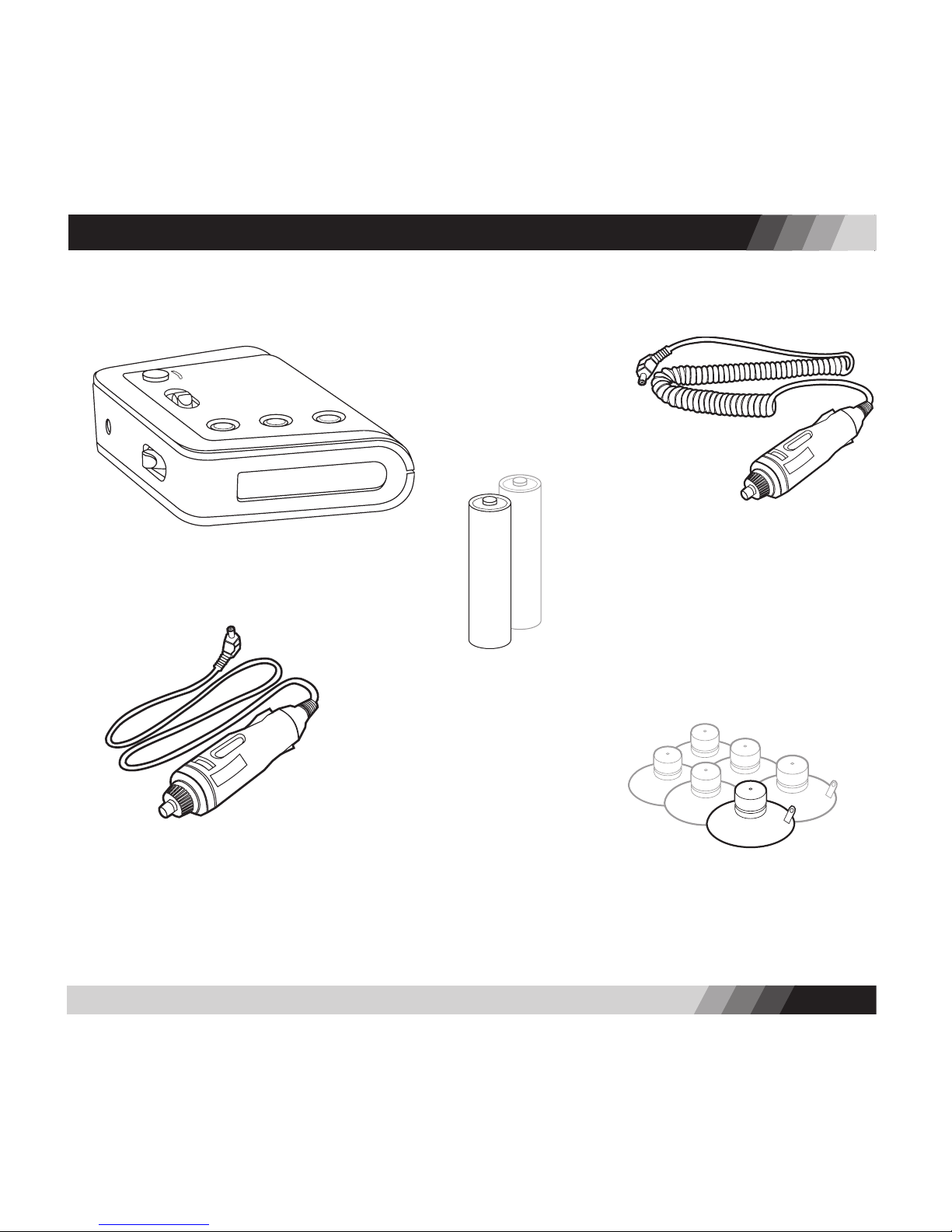
Your SILVER BULLET RX7500 package includes the following components:
PACKAGE CONTENTS
1. Radar/laser detector unit
2. Two AA alkaline batteries
3. 12V DC coiled power cord
4. 12V DC straight power cord 5. Six (6) suction cups

4
5
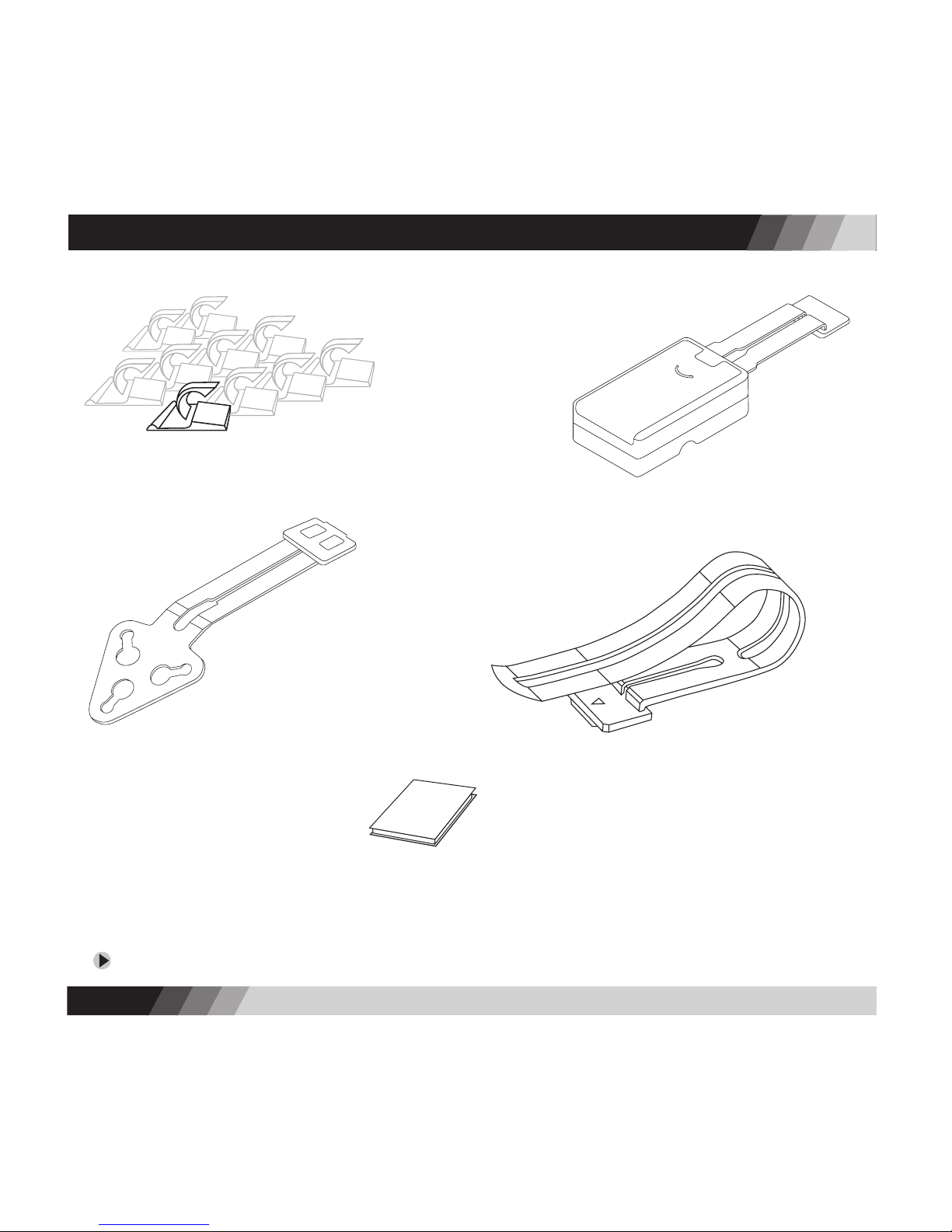
If you are missing any of these contents, please call our ofces at 1-888-422-6672 and we will ship them to you immediately.
PACKAGE CONTENTS
8. Windshield bracket B 9. Visor bracket
10. Hook & loop fastener
6. Ten (10) retaining clips
11. Operation manual
7. Windshield bracket A

4
5
CONTROLS
Speaker
Top Laser Receiver
POWER Switch
BACKLIGHT Button
MUTE Button
ALERT FILTER Button
TOP VIEW
LCD Screen
FRONT VIEW
Volume Controller
Power Cord Input Jack
SIDE VIEW
Radar Receiver
Front Laser Receiver
REAR VIEW

6
INSTALLATION
BRACKET A
The SILVER BULLET RX7500 can be easily installed on your windshield, visor, or dashboard. Each
location has its own installation hardware and requirements.
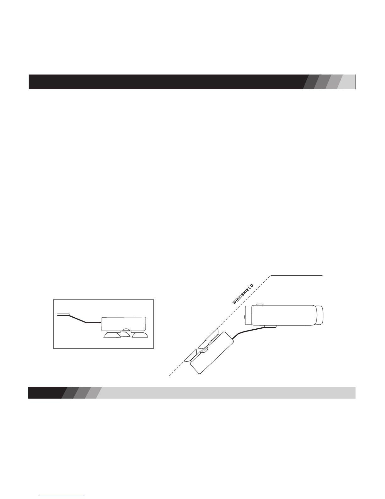
Windshield Installation – Battery Operation (use Bracket A)
1. Install 2 AA alkaline batteries into the windshield bracket A battery box (see Battery
Information, page 13).
2. Adjust mounting bracket. Bend the angle of the metal bars of the windshield bracket to set
the best viewing and detection angle, ensuring the radar detector is level with the road.
3. If suction cups are not installed in the bracket, insert the nipples of the suction cups into the
back of the battery box.
4. Secure to windshield. Press the bracket firmly against the windshield until the suction cups
take hold securely.
5. Mount the radar detector onto the plastic piece at the end of the bracket. You will hear a
“click” when the two parts are properly connected.

6
7
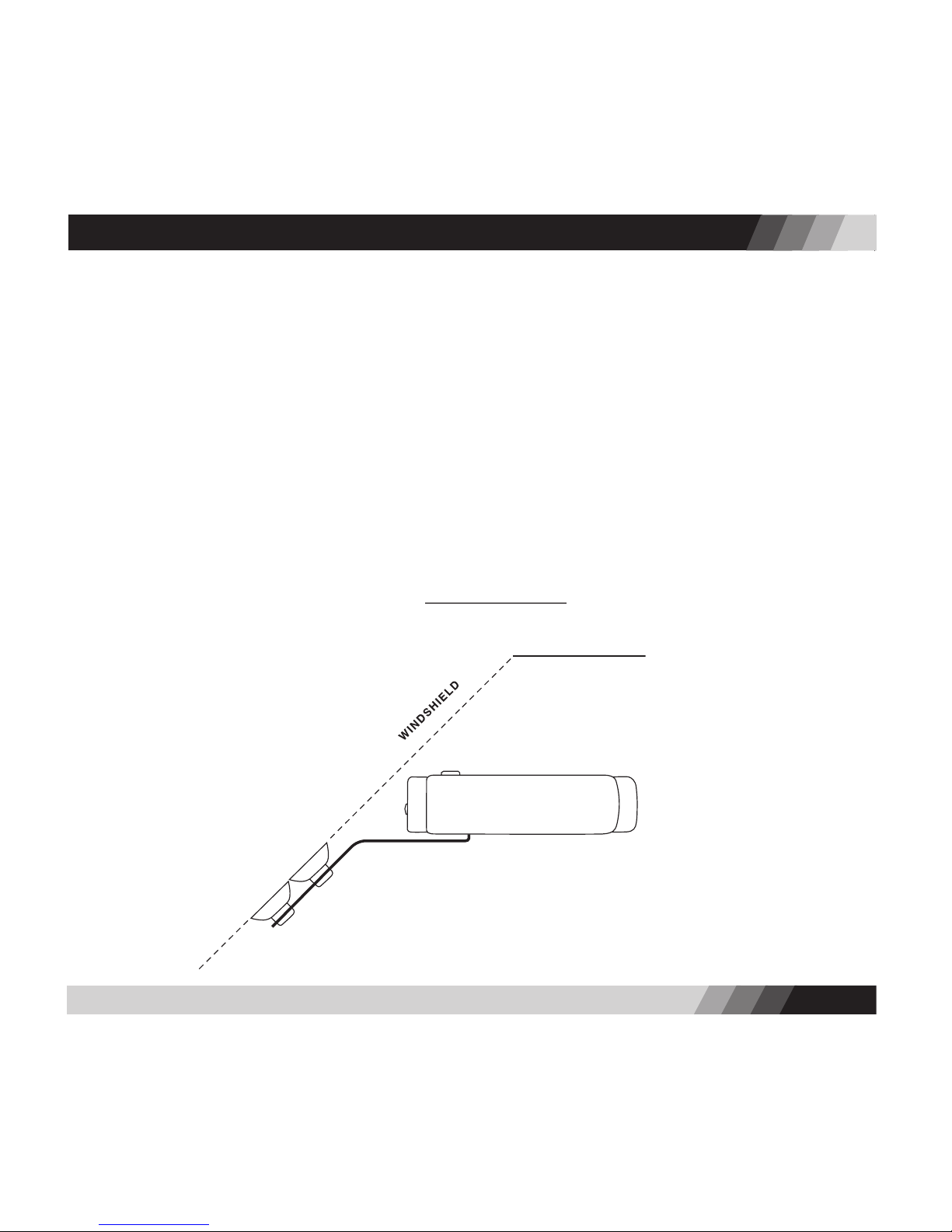
Windshield Installation – Power Cord Operation (use Bracket B)
1. Adjust mounting bracket. Bend the angle of the metal bars of the windshield bracket B to set
the best viewing and detection angle, ensuring the radar detector is level with the road.
2. If suction cups are not installed in the bracket, insert the nipples of the suction cups into the
windshield bracket.
3. Secure to windshield. Press the bracket rmly against the windshield until the suction cups
take hold securely.
4. Mount the radar detector onto the plastic piece at the end of the bracket. You will hear a “click”
when the two parts are properly connected.
5. Power-up. Plug the small end of the coiled power cord into the power jack on the side of the
radar detector. Plug the large end of the power cord into the power socket of your vehicle.
INSTALLATION

8
9
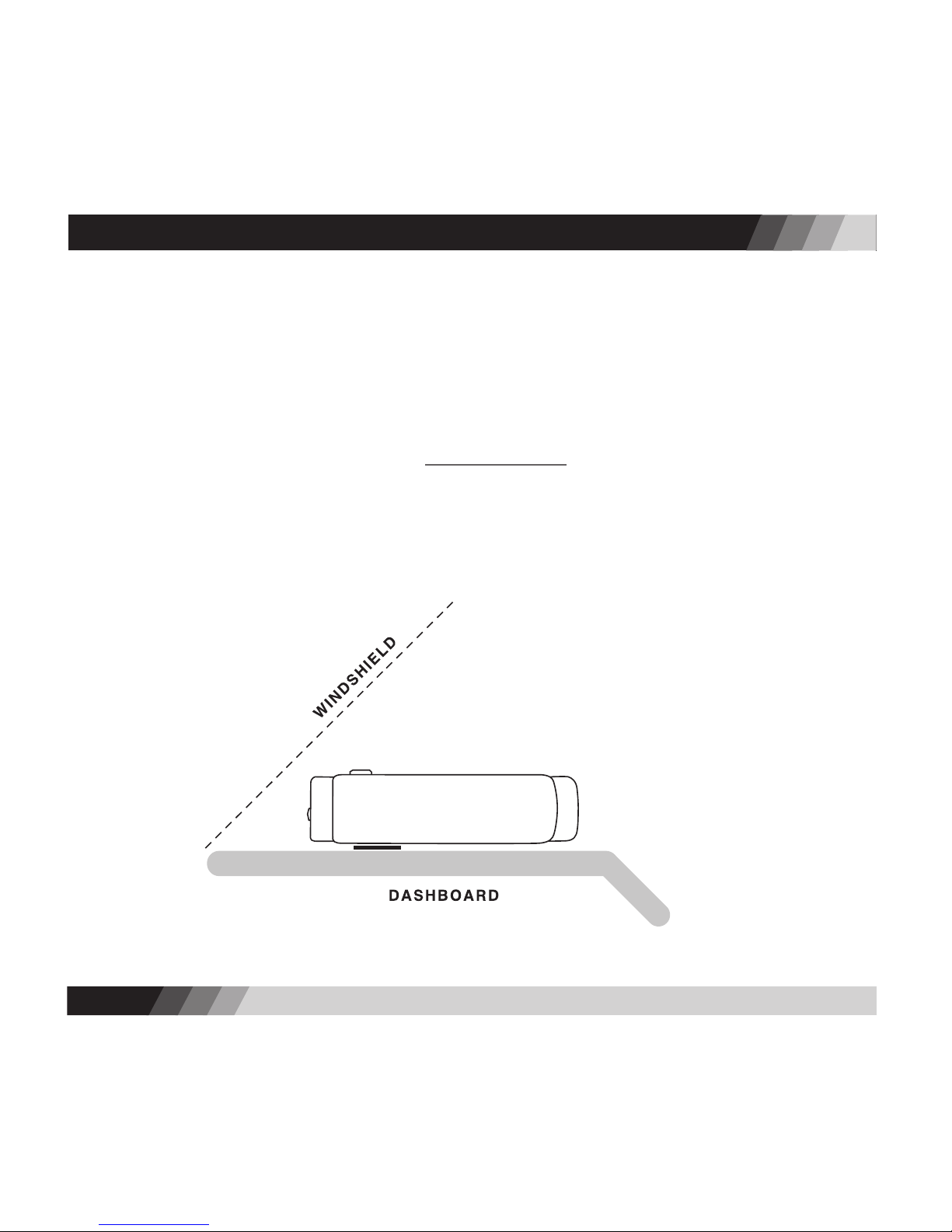
Dashboard Installation – Power Cord Operation only
1. Attach fastener. Peel off backing and adhere one side of the hook & loop fastener directly to
your dashboard, the other side to the bottom of the radar detector.
2. Attach the radar detector to the dashboard by placing the fastener pieces together.
3. Power-up. Plug the small end of the coiled power cord into the power jack on the side of the
radar detector. Plug the large end of the power cord into the power socket of your vehicle.
INSTALLATION

8
9
INSTALLATION
Visor Installation - Power Cord Operation only
1. Attach visor bracket. Clip the visor bracket to the back pivoting edge of your visor, so that the
plastic piece of the bracket faces downward when the visor is in its normal, stowed position.
2. Attach the radar detector to the bracket. Turn the radar detector upside down and mount it onto
the plastic end of the visor bracket. You will hear a “click” when the two parts are properly
connected. Make sure the screen faces you.
3. Power-up. Plug the small end of the straight power cord into the power jack on the side of the
radar detector. Plug the large end of the power cord into the power socket of your vehicle.
4. Turn on the unit by moving the power switch to ON.
5. Reverse the radar detectorʼs text display. Press and hold the MUTE and ALERT FILTER buttons
simultaneously for 3 seconds to reverse the text display (so messages will be seen right-side-up).
6. Use the retaining clips to attach any loose wire between the visor and the power socket. Be
careful not to leave any dangling wires that will distract the driver.

Choose where to install the Silver Bullet radar detector
The Silver Bullet can be installed on your windshield, dashboard or visor.
•Windshield installation includes both battery and power cord options.
•Dashboard and visor installations include power cord option only.
Installing your Radar Detector
BRACKET A
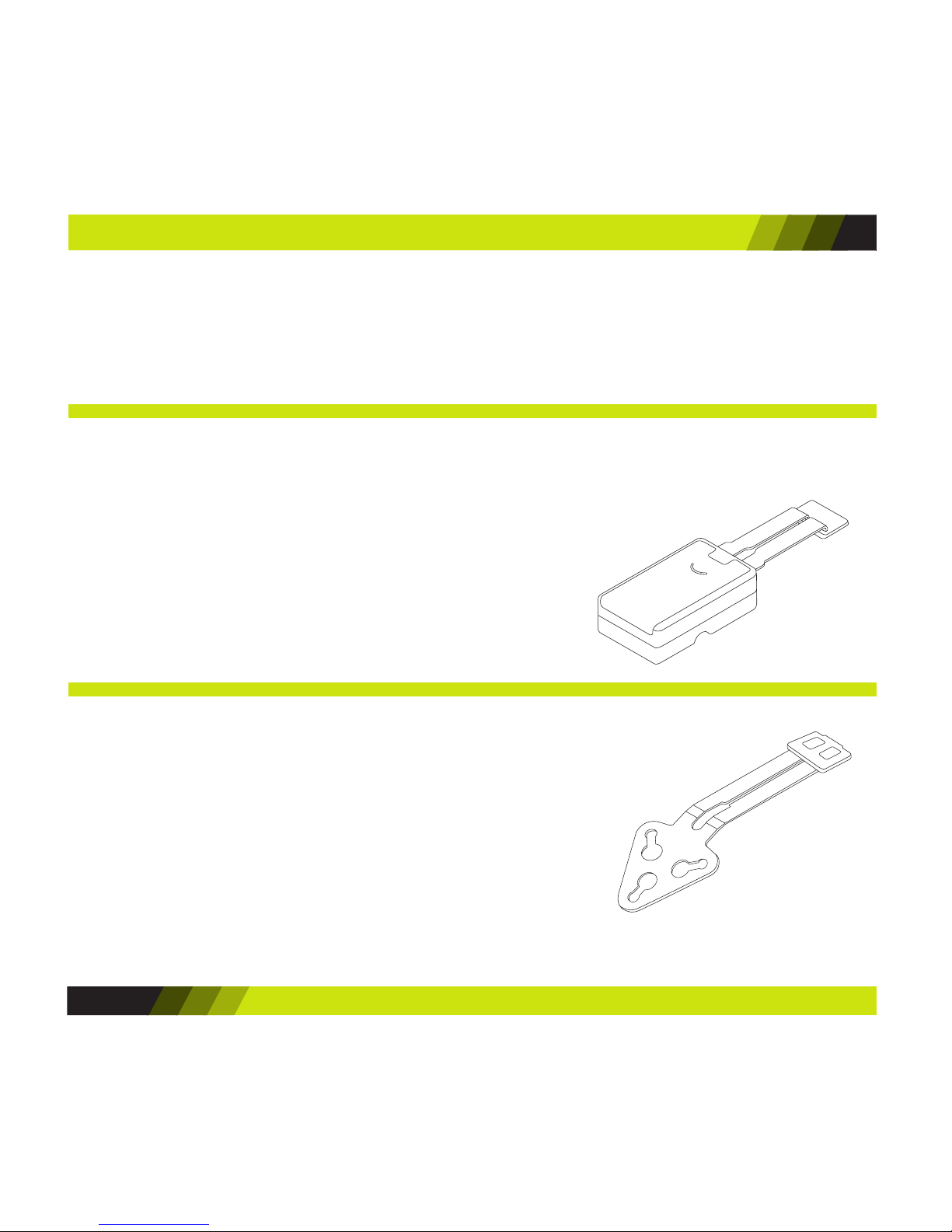
Windshield – Battery option (use Bracket A)
1. Install 2 AA alkaline batteries in the bracket battery box.
2. Bend the bracket bars as needed to ensure the radar
detector will be easily visible and level with the road.
3. Press securely against the windshield.
4. Attach the radar detector to the bracket – you will hear
a “click” when properly connected.
Windshield – Power Cord option (use Bracket B)
1. Bend the bracket bars as needed to ensure the radar
detector will be easily visible and level with the road.
2. Press securely against the windshield.
3. Attach the radar detector to the bracket – you will hear a
“click” when properly connected.
4. Plug the power cord into the radar detector and power
socket of your vehicle.
BRACKET B
QUICK GUIDE
10

Dashboard – Power Cord option (use Hook & Loop
fastener)
1. Mount the radar detector directly onto the dashboard
using the hook & loop fastener (with sticky sides
attached to the dashboard and bottom of radar detector).
2. Plug the power cord into the radar detector and power
socket of your vehicle.
Visor – Power Cord option (use Visor Bracket)
1. Clip visor bracket to the back, pivoting edge of your visor.
2. Turn the radar detector upside-down and attach to the visor
clip – you will hear a “click” when properly connected.
3. Attach the power cord to the radar detector.
4. Turn on the radar detector.
5. Press and hold the MUTE and ALERT FILTER buttons
simultaneously for 3 seconds to reverse the text display
(so messages will be seen right-side-up).
6. Use the retaining clips to neatly tuck away the power cord.
Turning On the Radar Detector
1. Move the POWER switch to ON.
2. The screen will display ”SENSORO RADAR DETECTOR * * *
FILTER-NORMAL” indicating a normal lter mode.
3. The screen will then display “SYSTEM ON”.
HOOK & LOOP FASTENER
VISOR BRACKET
QUICK GUIDE
11

13
Understanding Alert Messages
1. When a radar signal is detected, the screen displays the
name of the band – “X”, “K”, or “KA” – and a number
indicating the strength of the signal (1 to 8).
2. The higher the number, the stronger the signal.
3. Stronger signals usually imply that youʼre closer to a police
radar/laser device.
4. When a laser signal is detected, the screen displays “LASER”.
Adjusting the Alert Filter
If you receive too many false alert signals, or are driving in
specic environments, press the ALERT FILTER button to switch
between lter modes:
•FILTER-NORMAL – Optimized ltering for typical city or
highway driving
•FILTER-HIGH – Increased ltering to reduce most false
alerts, good for high-density commercial areas
•FILTER-OFF – No ltering of alert signals, ideal for open
space areas
QUICK GUIDE
12

13
OPERATION DETAILS
Battery Information
The SILVER BULLET RX7500 operates on two AA alkaline batteries. To ensure optimum performance
and battery life, we advise against using other types of batteries. Using AA rechargeable batteries
is NOT recommended as the resulting battery life will be shorter due to characteristics of
rechargeable batteries
Battery Installation
1. BE SURE the radar detector is turned off; disconnect the battery box from the radar detector.
2. Remove the battery door on the battery box.
3. If replacing batteries, remove old batteries by pulling the battery removal ribbon.
Do not mix old and new batteries for maximum battery life.
4. Insert two fresh AA alkaline batteries into the battery box, observing the polarity indication
inside the battery box.
5. Replace the battery box door and reconnect the battery box to the radar detector.
6. The radar detector is ready for use.

14
15
Battery Life
The SILVER BULLET RX7500 can provide approximately 30-40 hours of battery life from two AA alkaline
batteries. Battery life is affected by many variables, such as the brand and condition of the batteries, the
ambient temperature, the number and strength of engaged signals, and the duration of reported alerts,
backlight, and user settings. The estimated battery life provided here is based on battery aging tests
conducted in laboratory environments.
Low Battery Indicator
A “LOW BATTERY” message will appear when 2 to 4 hours of battery life remain. This message will scroll
across the screen for 10 seconds accompanied by a beeping sound. This will repeat every 30 minutes until
no battery power remains and the radar detector shuts off.
We suggest keeping the power cord readily available. If your batteries are drained, the cord
will allow you to continue using your radar detector until you can replace the batteries.
Auto Power-Off
To conserve battery power, the SILVER BULLET RX7500 will automatically shut off when no signal detection
and no button manipulation have occurred for 40 minutes. The radar detector will display ”ENTERING
SLEEP MODE… PRESS ANY BUTTON TO STAY ON” and will beep for 20 seconds before powering down. To
keep the radar detector on, just press any button while the audio and visual warnings are displayed.
The automatic power-off does not function when the radar detector is operated by power cord.
Please turn off the radar detector whenever you leave your vehicle. Even a weak signal can
cause it to remain on and drain your batteries.
If the radar detector was turned off automatically, you can turn it back on by pressing any
button, or by moving the power switch to OFF and then to ON.
OPERATION DETAILS

14
15
OPERATION DETAILS
Turning On the Radar Detector
•Move the POWER switch to ON.
•The screen will display ”SENSORO RADAR DETECTOR * * * FILTER-NORMAL” if itʼs your rst use
since purchase.
•If you selected an alternate alert lter mode during previous use, it will display either “FILTER-
HIGH” or “FILTER-OFF” instead of “FILTER-NORMAL” in the message above per your selection.
•The screen will then display “SYSTEM ON”.
Using the Backlight
Press the BACKLIGHT button to switch the backlight on or off. The radar detector will sound 1 beep
when the backlight is turned on, and 2 beeps when it is turned off.
If the backlight stays on for more than 15 minutes, the screen will scroll twice ”BACKLIGHT IS
ON… TURNING OFF WILL PROLONG YOUR BATTERY LIFE”. This will repeat every 15 minutes.
The backlight is automatically on for 5 to 20 seconds at the following events:
•While the tutorial messages are displayed – 15 seconds
•While the auto power-off messages are displayed – 20 seconds
•While the low battery message is displayed – 10 seconds
•When a button is pressed – 5 seconds
•When an alert message is displayed – 5 seconds

16
17
Using the Mute Feature
Press the MUTE button to switch between “START MUTE” and “END MUTE”. In the “END MUTE” mode,
the radar detector automatically lowers the audio alert level to the ambient noise level in your vehicle
when it detects a continuous signal for 5 seconds or more. Also the audio alert level remains low
for 60 seconds, even if, during that time, a second separate signal is detected. In the “START MUTE”
mode, the radar detector will remain completely silent but will continue to provide visual alerts.
Understanding Signal Alerts
Three (3) radar bands (X, K, and superwide KA) and one (1) laser band are typically used by police
radar/laser devices. When a radar signal is detected, the screen displays the name of the radar band
– “X”, “K”, or “KA” – together with a number indicating the strength of the detected signal (called
the signal strength meter). When a laser signal is detected, the screen displays “LASER”.
• There are 8 levels in the signal strength meter – 1 to 8. The higher the number, the
stronger the signal.
• The signal strength meter can provide a good indication of the proximity of the detected
signal. Usually, strong signals are closer to you than weak signals.
• When “LASER” alert is displayed, it is highly recommended that you promptly reduce your
speed if youʼre driving faster than the speed limit. Police laser devices can measure the
speed of a target vehicle when it is within 1,500 feet in line of sight.
Except for a few early devices, X band (10.50~10.55 GHz) was the only frequency used for
police radar until the mid-1970ʼs. In 1976 radar devices using K band (24.05~24.25 GHz)
were introduced; this led to the development of the rst dual band (X and K) radar detectors.
OPERATION DETAILS

16
17
OPERATION DETAILS
A proliferation of radar devices using KA band frequencies began in 1987 with the
introduction of photo radar (34.3 GHz) and was followed by the Stalker (34.2~35.2
GHz) in 1991 and the BEE 36A (33.4~34.4 GHz) in 1992.
Early detectors needed only to listen for X band radar. When K band arrived, dual band
detectors able to receive both frequencies (X and K) were required. The introduction of KA
band photo radar (34.3 GHz) led to the development of tri-band detectors able to detect X, K,
and a small portion of KA band. A fourth category of radar receivers called “wide-band” with
X, K, and wide KA (34.2~35.2 GHz) band detection capabilities reached the market following
the introduction of Stalker radar. Finally, in response to the BEE 36A, a new generation of
“superwide-band” radar detectors was developed. They detect all radar devices operating
on X, K, and superwide KA (33.4~36.0 GHz) band. All SENSORO radar/laser detectors are
superwide band receivers.
Laser devices transmit an invisible light beam at a frequency (more accurately a
“wavelength”) of 904 nanometers. A nanometer is how a light wavelength is measured.
Different laser devices operate at different light pulse rates and some manufacturers call them
“bands”. All SENSORO radar/laser detectors can detect all current laser devices in use.
Less than 1,000 laser devices are in service in 45 states at present. Most are used by city police
on urban multi-lane roadways. The use of laser devices for speed monitoring is expected to
increase, but will remain limited due to their high cost and limited attractiveness to agencies
that favor the convenience, offered by conventional moving radar. Currently, laser guns
account for less than 5% of the total number of speed monitoring devices (radar and laser)
sold in the U.S. annually; during the next ve years, this gure is expected to remain under
8%. Laser devices will likely be in service in every state within a few years.

18
19
OPERATION DETAILS
Using the Alert Filter Button
Press the ALERT FILTER button to switch between lter modes. The factory default is FILTER-NORMAL.
•FILTER-NORMAL – Optimized ltering for typical city or highway driving. The NORMAL mode
lters out all X band and other known radar signals commonly associated with annoying false
alerts in city and suburban areas. When this mode is selected, the screen will scroll “FILTER-
NORMAL MODE”.
•FILTER-HIGH – Increased ltering to reduce most false alerts, good for high-density commercial
areas. The HIGH mode is ideal when youʼre receiving frequent false alerts. Most North
American speed monitoring systems use the K or KA bands, and this mode will not adversely
affect the sensitivity to police radar/laser devices. When this mode is selected, the screen will
scroll “FILTER-HIGH MODE”.
•FILTER-OFF – No ltering of alert signals, ideal for open space areas. The OFF mode eliminates
the X band lter and is recommended for driving in areas where X band radar devices are still
in use. While now being phased out in most areas, X band is still used in some locations. When
this mode is selected, the screen will scroll “FILTER-OFF MODE”.
X band, occupied by police radar, is also used for other devices, such as automatic door
openers like those at supermarkets, burglar alarms, terrestrial microwave emission, and
more. In addition, other radar detectors in close proximity may falsely alert your detector.
Filtering false alerts will help you travel more comfortably.
Invisibility to VG-2 Devices
VG-2 is a technology used by speed monitoring systems to identify vehicles equipped with radar detectors
in instances and locations where they are not legal (such as in vehicles over 10,000 lbs. or in Virginia
and Washington D.C.). The VG-2 interceptors work by detecting emission frequencies (11.4~11.7 GHz)

18
19
generated by radar detectors. The Silver Bullet RX7500 does not generate emissions detectable by these
VG-2 radar detector-sensing devices.
Tutorial Mode
The Silver Bullet RX7500 includes a tutorial mode to familiarize you with the radar detectorʼs visual
displays and distinct audio alarms. To activate the on-screen tutorial, press and hold the BACKLIGHT
button for 5 seconds. The screen will display the following visual messages, each with a unique audio
alarm that distinguishes it from the other messages.
X band detected operation:
K band detected operation:
Ka band detected operation:
Instant-on signal detected operation:
Laser band detected operation:
After the tutorial is nished, the screen will automatically revert back to displaying “SYSTEM ON“.
OPERATION DETAILS
X 8 X 2 X 4 X 6
K 8 K 2 K 4 K 6
KA 8 KA 2 KA 4 KA 6
INSTANT
X 3
INSTANT
K 5
INSTANT
KA 7
LASER

20
21
TROUBLESHOOTING
Your SILVER BULLET RX7500 is designed to deliver consistent and reliable service. If you encounter a
problem, please refer to this section before returning your radar detector.
•The radar detector does not power up when intended to operate by battery power.
— Check and replace batteries.
— Check all connections between the radar detector and the battery box.
•The radar detector does not power up when intended to operate by power cord.
— Check all power cord connections.
— Check fuse in 12 volt adapter and replace if necessary;
see Fuse Replacement for detail.
— Check power outlet in your vehicle. Clean if dirty.
— Check your vehicleʼs fuse panel.
Fuse Replacement: The 12 volt adapter of the power cord has a replaceable 2-Amp SAG fuse
located below the silver tip. To check or replace the fuse, slowly and carefully unscrew the tip
of the plug, making sure the spring and silver tip located inside the plug do not y out when
you remove the cap. Check fuse and replace if necessary.
•The radar detector did not alert when passing an ofcer.
— Not all police ofcers are equipped with a radar/laser device, or it may not have been in use
at that time.
•The radar detector shows erratic or frequent false alerts.
— Use FILTER-NORMAL or FILTER-HIGH mode.
•The radar detector does not alert early enough.
— Make sure the radar detector is level to the road.
— Make sure the radar window or the top laser receiver is not obstructed. Move the radar detector if
necessary.
Table of contents
Other PNI Radar Detector manuals