PNI SENSORO SILVER BULLET RX7600 User manual

CONTENTSCONTENTS
WELCOME
Features ....................................................................................................................................................................... 2
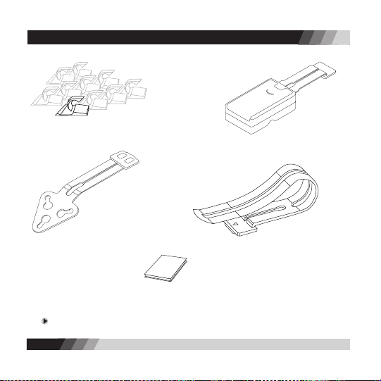
Package Contents ....................................................................................................................................................... 3
Controls ....................................................................................................................................................................... 5
ABOUT RADAR / LASER DETECTION ............................................................................................................................... 6
INSTALLATION .................................................................................................................................................................... 8
Windshield Installation - battery operation ............................................................................................................ 8
Windshield Installation - power cord operation .................................................................................................... 9
Dashboard Installation .............................................................................................................................................. 10
Visor Installation ......................................................................................................................................................... 11
QUICK GUIDE ..................................................................................................................................................................... 12
OPERATION DETAILS ......................................................................................................................................................... 16
BATTERY INFORMATION ............................................................................................................................................ 16
Battery Installation ................................................................................................................................................ 16
Battery Life ............................................................................................................................................................. 17
Low Battery lndicator ............................................................................................................................................ 17
Auto Power-Off ...................................................................................................................................................... 17
TURNING ON THE RADAR DETECTOR ..................................................................................................................... 18
SETTING UP THE COMPASS ...................................................................................................................................... 18
USING THE BACKLIGHT ............................................................................................................................................. 20
USING THE MUTE FEATURE ...................................................................................................................................... 21
UNDERSTANDING SIGNAL ALERTS ......................................................................................................................... 21
USING THE ALERT FILTER BUTTON ......................................................................................................................... 22
INIVISIBILITY TO VG-2 DEVICES ............................................................................................................................... 22
TUTORIAL MODE ....................................................................................................................................................... 23
TROUBLESHOOTING ......................................................................................................................................................... 25
SERVICE AND REPLACEMENT .......................................................................................................................................... 26
WARRANTY INFORMATION ............................................................................................................................................. 28

2
CONTENTS
3
Congratulations on your purchase of the SENSORO SILVER BULLET RX7600, the ultra compact,
wireless radar/laser detector by PNI Corporation. The SILVER BULLET RX7600’s patented,
innovative technology brings you long-range radar detection in an incredibly compact, slim
package. The SILVER BULLET attaches easily to your windshield, dashboard, or visor.
Please visit our website at www.pnicorp.com for technical specications for the SILVER BULLET
RX7600 and to download the most recent versions of this manual.
Features
• All-band radar and laser signal detection
• Built-in digital compass displaying 16 cardinal points
• Undetectable by VG-2 radar-detecting devices
• 360-degree radar and laser coverage
• Identies instant-on radar signals
• 3 alert lter modes: FILTER-NORMAL, FILTER-HIGH, and FILTER-OFF
• 8 signal strength meter levels
• LCD screen with bright backlight
• Separate power on/off switch and volume control
• Automatic audio control
• Automatic power-off
• Retains previously set operation modes after power off
• Tutorial mode to demonstrate operations
• Operates on 2 AA batteries or 12V DC power adapter
• Mounts on windshield, dashboard, or visor
WELCOME

2
CONTENTS
3
Your SILVER BULLET RX7600 package includes the following components:
PACKAGE CONTENTS
1. Radar/laser detector unit
2. Two AA alkaline batteries
3. 12V DC coiled power cord
4. 12V DC straight power cord 5. Six (6) suction cups

4
5
PACKAGE CONTENTS
If you are missing any of these contents, please call us at 1-888-422-6672 and we will ship them
to you immediately.
8. Windshield bracket B 9. Visor bracket
10. Hook & loop fastener
6. Ten (10) retaining clips
11. Operation manual
7. Windshield bracket A

4
5
CONTROLS
Speaker
Top Laser Receiver
POWER Switch
BACKLIGHT Button
MUTE Button
ALERT FILTER Button
TOP VIEW
LCD Screen
FRONT VIEW
Volume Controller
Power Cord Input Jack
SIDE VIEW
Radar Receiver
Front Laser Receiver
REAR VIEW

6
7
Radar Devices
Until the mid-1970’s, X band (10.50~10.55 GHz) was the only frequency used by most police radar
devices. Early radar detectors needed only to listen for X band radar. But in 1976 police radar
devices using K band (24.05~24.25 GHz) were introduced, leading to the development of the rst
dual band detectors able to receive both frequencies (X and K).
Then, in 1987, a proliferation of police radar devices using KA band frequencies began with the
introduction of photo radar (34.3 GHz), followed by the Stalker (34.2~35.2 GHz) in 1991 and the
BEE 36A (33.4~34.4 GHz) in 1992. The introduction of KA band photo radar (34.3 GHz) led to the
development of tri-band detectors able to detect X, K, and a small portion of KA band. A fourth
category of “wide-band” radar detectors capable of detecting X, K, and wide KA (34.2~35.2 GHz)
bands reached the market following the introduction of Stalker radar.
Finally, in response to the BEE 36A, a new generation of “superwide-band” radar detectors was
developed. They detect all police radar devices operating on X, K, and superwide KA (33.4~36.0
GHz) bands. All SENSORO radar/laser detectors are superwide band receivers.
When radar detectors proved easily capable of detecting radar from miles away, radar device
manufacturers responded by developing “instant-on radar.” In the instant-on mode, the radar’s
transmitter is placed on hold, ready to re but not yet producing a signal for detectors to hear. The
ofcer waits until his target is very close, releases the radar from stand-by mode, and gets a speed
reading within a second or so.
In this situation, no detector can offer much warning. But the SILVER BULLET is designed to display
“INSTANT” when an instant-on signal is detected, followed by the name of the detected radar band.
When an “INSTANT” alert is displayed, we recommend that you promptly reduce your speed if
you’re driving faster than the speed limit.
ABOUT RADAR / LASER DETECTOR

6
7
Laser Devices
Laser devices transmit an invisible light beam at a frequency (more accurately a “wavelength”)
of 904 nanometers. A nanometer is how a light wavelength is measured. Different laser devices
operate at different light pulse rates and some manufacturers call them “bands.” All SENSORO
radar/laser detectors can detect all current laser devices in use.
Less than 1,000 laser devices are in service in 45 states at present. Most are used by city police on
urban multi-lane roadways. The use of laser devices for speed monitoring is expected to increase,
but will remain limited due to their high cost and limited attractiveness to agencies that favor the
convenience of conventional moving radar. Currently, laser guns account for less than 5% of the
total number of speed monitoring devices (radar and laser) sold in the U.S. annually; during the
next ve years, this gure is expected to remain under 8%. Laser devices will likely be in service in
every state within a few years.
Laser devices can measure the speed of a target vehicle only when it is up to 1,500 feet away in
line of sight. This means that when the “LASER” alert is displayed, the speed monitoring system
is nearby. When the SILVER BULLET “LASER” alert is displayed, we highly recommend that you
promptly reduce your speed if you’re driving faster than the speed limit.
ABOUT RADAR / LASER DETECTOR

8
9
You can easily install the SILVER BULLET RX7600 on your windshield, visor, or dashboard. Each
location has its own installation hardware and requirements.
Windshield Installation – Battery Operation (use Bracket A)
1. Install 2 AA alkaline batteries into the windshield bracket A battery box (see Battery
Information, page 16).
2. Adjust mounting bracket. Bend the angle of the metal bars of the windshield bracket to set
the best viewing and detection angle, ensuring the radar detector is level with the road.
3. If suction cups are not installed in the bracket, insert the nipples of the suction cups into
the back of the battery box.
4. Secure to windshield. Press the bracket firmly against the windshield until the suction cups
take hold securely.
5. Mount the radar detector onto the plastic piece at the end of the bracket. You will hear a
“click” when the two parts are properly connected.
INSTALLATION
BRACKET A

8
9
Windshield Installation – Power Cord Operation (use Bracket B)
1. Adjust mounting bracket. Bend the angle of the metal bars of the windshield bracket B to
set the best viewing and detection angle, ensuring the radar detector is level with the road.
2. If suction cups are not installed in the bracket, insert the nipples of the suction cups into
the windshield bracket.
3. Secure to windshield. Press the bracket firmly against the windshield until the suction cups
take hold securely.
4. Mount the radar detector onto the plastic piece at the end of the bracket. You will hear a
“click” when the two parts are properly connected.
5. Power-up. Plug the small end of the coiled power cord into the power jack on the side of
the radar detector. Plug the large end of the power cord into the power socket of your
vehicle.
INSTALLATION

10
11
Dashboard Installation – Power Cord Operation only
1. Attach fastener. Peel off backing and adhere one side of the hook & loop fastener directly to
your dashboard, the other side to the bottom of the radar detector.
2. Attach the radar detector to the dashboard by placing the fastener pieces together.
3. Power-up. Plug the small end of the coiled power cord into the power jack on the side of the
radar detector. Plug the large end of the power cord into the power socket of your vehicle.
INSTALLATION

10
11
Visor Installation - Power Cord Operation only
1. Attach visor bracket. Clip the visor bracket to the back pivoting edge of your visor, so that the
plastic piece of the bracket faces downward when the visor is in its normal, stowed position.
2. Attach the radar detector to the bracket by turning the radar detector upside down and
mounting it onto the plastic end of the visor bracket. You will hear a “click” when the two parts
are properly connected. Make sure the LCD screen faces you.
3. Power-up. Plug the small end of the straight power cord into the power jack on the side of the
radar detector. Plug the large end of the power cord into the power socket of your vehicle.
4. Turn on the radar detector by moving the power switch to ON.
5. Reverse the radar detector’s text display. Press and hold the MUTE and ALERT FILTER buttons
simultaneously for 3 seconds to reverse the text display (so messages will be seen right-side-up).
6. Use the retaining clips to attach any loose wire between the visor and the power socket. Be
careful not to leave any dangling wires that will distract the driver.
INSTALLATION

Choose where to install the Silver Bullet radar detector
The Silver Bullet can be installed on your windshield, dashboard or visor.
• Windshield installation includes both battery and power cord options.
• Dashboard and visor installations include power cord option only.
QUICK GUIDE
12
Installing your radar detector
Windshield – Battery option (use Bracket A)
1. Install 2 AA alkaline batteries in the bracket battery box.
2. Bend the bracket bars as needed to ensure the radar
detector will be easy to read and level with the road.
3. Press securely against the windshield.
4. Attach the radar detector to the bracket – you will hear a
“click” when properly connected.
Windshield – Power Cord option (use Bracket B)
1. Bend the bracket bars as needed to ensure the radar
detector will be easy to read and level with the road.
2. Press securely against the windshield.
3. Attach the radar detector to the bracket – you will hear a
“click” when properly connected.
4. Plug the power cord into the radar detector and power
socket of your vehicle.
BRACKET A
BRACKET B

QUICK GUIDE
13
Dashboard – Power Cord option (use Hook & Loop
fastener)
1. Mount the radar detector directly onto the dashboard
using the hook & loop fastener (with sticky sides attached
to the dashboard and bottom of radar detector).
2. Plug the power cord into the radar detector and power
socket of your vehicle.
Visor – Power Cord option (use Visor Bracket)
1. Clip visor bracket to the back, pivoting edge of your visor.
2. Turn the radar detector upside-down and attach to the
visor clip – you will hear a “click” when properly
connected.
3. Attach the power cord to the radar detector.
4. Turn on the radar detector.
5. Press and hold the MUTE and ALERT FILTER buttons
simultaneously for 3 seconds to reverse the text display
(so messages will be seen right-side-up).
6. Use the retaining clips to neatly tuck away the power cord.
Turning on the radar detector
1. Move the POWER switch to ON.
2. The screen will display ”SENSORO RADAR DETECTOR * * *
FILTER-NORMAL” indicating a normal lter mode.
3. The screen will then display a random compass direction
if the compass has not been set-up since purchase.
HOOK & LOOP FASTENER
VISOR BRACKET

14
Setting up the compass
To set the compass readings you will need to drive your
vehicle slowly in a full circle. Be sure you are in an area
where you can safely perform this maneuver.
1. Install the radar detector in your vehicle at your
preferred location - windshield, dashboard, or visor.
2. Press and hold the BACKLIGHT and MUTE buttons
simultaneously for 3 seconds.
3. The screen will display “DRIVE IN A FULL CIRCLE...
PRESS ANY BUTTON WHEN DONE.”
4. Drive your vehicle in a full circle. The direction and size
of circle do not matter. You have one minute to
complete the maneuver.
5. Press any button to complete the compass set-up.
Understanding alert messages
1. When a radar signal is detected, the screen displays
the name of the band – “X”, “K”, or “KA” – and a
number indicating the strength of the signal (1 to 8).
2. When a laser signal is detected, the screen displays
“LASER”.
3. The higher the number, the stronger the signal.
4. Stronger signals usually mean the police radar/laser
device is relatively close; weaker signals usually mean
it’s farther away.
QUICK GUIDE

Adjusting the Alert Filter
If you receive too many false alert signals, or are driving
in specic environments, press the ALERT FILTER button to
switch between lter modes:
1. FILTER-NORMAL – Optimized ltering for typical city or
highway driving
2. FILTER-HIGH – Increased ltering to reduce most false
alerts, good for high-density commercial areas
3. FILTER-OFF – No ltering of alert signals, ideal for open
space areas
QUICK GUIDE
15

16
17
Battery Information
The SILVER BULLET RX7600 operates on two AA alkaline batteries. To ensure optimum performance
and battery life, we recommend you not use other types of batteries. We also do NOT recommend
using AA rechargeable batteries as the resulting battery life will be shorter due to characteristics
of rechargeable batteries.
Battery Installation
1. BE SURE the radar detector is turned off; disconnect the battery box from the radar detector.
2. Remove the battery door on the battery box.
3. If replacing batteries, remove old batteries by pulling the battery removal ribbon.
For maximum battery life, do not mix old and new batteries.
4. Insert two fresh AA alkaline batteries into the battery box, observing the polarity indication
inside the battery box.
5. Replace the battery box door and reconnect the battery box to the radar detector.
6. The radar detector is ready for use.
OPERATION DETAILS

16
17
Battery Life
The SILVER BULLET RX7600 can provide approximately 30-40 hours of battery life from two AA
alkaline batteries. Battery life is affected by many variables, such as the brand and condition of the
batteries, the ambient temperature, the number and strength of engaged signals, and the duration
of reported alerts, backlight, and user settings. The estimated battery life provided here is based on
battery aging tests conducted in laboratory environments.
Low Battery Indicator
A “LOW BATTERY” message will appear when 2 to 4 hours of battery life remain. This message will
scroll across the screen for 10 seconds accompanied by a beeping sound. This will repeat every 30
minutes until no battery power remains and the radar detector shuts off.
We suggest keeping the power cord readily available. If your batteries are drained, the cord will
allow you to continue using your radar detector until you can replace the batteries.
Auto Power-Off
To conserve battery power, the SILVER BULLET RX7600 will automatically shut off when there
happens no change for 10 minutes to the magnetic eld data that the compass is sensing. The
radar detector will display ”ENTERING SLEEP MODE… PRESS ANY BUTTON TO STAY ON” and will
beep for 20 seconds before powering down. To keep the radar detector on, just press any button
while the audio and visual warnings are displayed.
The automatic power-off does not function when the radar detector is operated by power cord.
Please turn off the radar detector whenever you leave your vehicle. Even a weak signal can cause
it to remain on and drain your batteries.
If the radar detector turns off automatically, you can turn it back on by pressing any button, or
by moving the power switch to OFF and then to ON.
OPERATION DETAILS

18
19
Turning On the Radar Detector
• Move the POWER switch to ON.
• The screen will display ”SENSORO RADAR DETECTOR * * * FILTER-NORMAL” if it’s your rst use
since purchase.
• If you selected an alternate alert lter mode during previous use, it will display either “FILTER-
HIGH” or “FILTER-OFF” instead of “FILTER-NORMAL” in the message above, per your selection.
• The screen will then display a random compass direction if the compass has not been set-up
since purchase.
Setting Up the Compass
The digital compass built into the SILVER BULLET RX7600 allows you to determine the direction
your vehicle is heading at all times. To provide accurate directional readings, the compass must
be set-up (calibrated) . This allows the compass to separate the earth’s magnetic eld from the
magnetic elds generated by your vehicle.
IN ORDER TO SET-UP THE COMPASS YOU WILL NEED TO DRIVE YOUR VEHICLE SLOWLY IN A FULL
CIRCLE, SO BE SURE YOU ARE IN AN AREA WHERE YOU CAN SAFELY PERFORM THIS MANEUVER.
When to set up the compass:
•
When the radar detector is rst installed in your vehicle.
•
When you move the radar detector to a different location from where the compass was
previously set up.
•
When the compass heading is inaccurate.
OPERATION DETAILS

18
19
How to set up the compass:
1. Be sure the radar detector is properly installed in your preferred location – on the windshield,
the visor, or the dashboard of your vehicle.
2. Press and hold the BACKLIGHT and MUTE buttons simultaneously for 3 seconds until you
hear the radar detector beep once. The screen will display “DRIVE IN A FULL CIRCLE… PRESS
ANY BUTTON WHEN DONE”. You will have one minute to complete the maneuver.
3. Drive your vehicle in a full 360o circle. The size of the circle and direction of your vehicle do
not matter. The circle does not need to be perfectly round but must be completed going in the
same direction.
4. Press any button to complete the compass set-up. The radar detector will beep twice and
display “SET-UP COMPLETE” if the set-up was successful.
If there was an error during set-up, the radar detector will display “SET-UP INCOMPLETE… PRESS
MUTE TO RESTART SET-UP… PRESS BACKLIGHT TO CANCEL SET-UP”.
• Press the MUTE button to restart the set-up. The radar detector will display “DRIVE IN A FULL
CIRCLE… PRESS ANY BUTTON WHEN DONE”. Try again to drive your vehicle in a full 360 o
circle, then press any button to complete the set-up.
• Press the BACKLIGHT button to cancel the set-up. The radar detector will display “SET-UP
CANCELLED” and exit from the compass set-up process. The radar detector may indicate
inaccurate directions until the compass set-up is successfully completed.
• When none of the buttons are pressed during the warning signal, the radar detector will display
“SET-UP CANCELLED” and exit from the compass set-up process.
The radar detector will ignore any signal threats during the compass set-up process.
OPERATION DETAILS

20
21
Additional compass set-up information:
• If possible, select a level section of pavement, such as an empty parking lot or non-busy street,
to complete the compass set-up.
• Take a minimum of 20 seconds but less than 1 minute to drive in a circle during the set-up
process.
• If you take more than 1 minute to complete the circle, the radar detector will display “PRESS ANY
BUTTON TO COMPLETE SET-UP”.
• Press any of the buttons during the warning signal to complete the set-up.
• If you leave the radar detector untouched during this warning signal, it will display “SET-UP
INCOMPLETE… PRESS MUTE TO RESTART SET-UP… PRESS BACKLIGHT TO CANCEL SET-UP”.
You can immediately restart the compass set-up by pressing the MUTE button or cancel the
set-up by pressing the BACKLIGHT button or by not pressing any of the buttons.
Using the Backlight
Press the BACKLIGHT button to switch the backlight on or off. The radar detector will sound 1 beep
when the backlight is turned on, and 2 beeps when it is turned off.
If the backlight stays on for more than 15 minutes, the screen will scroll twice ”BACKLIGHT IS
ON… TURNING OFF WILL PROLONG YOUR BATTERY LIFE”. This will repeat every 15 minutes.
The backlight is automatically on for 5 to 20 seconds at the following events:
• While the auto power-off messages are displayed – 20 seconds
• While the tutorial messages are displayed – 15 seconds
• While the low battery message is displayed – 10 seconds
• When a button is pressed – 5 seconds
• When an alert message is displayed – 5 seconds
OPERATION DETAILS
Table of contents
Other PNI Radar Detector manuals