PoKeys 56U User manual

PoKeys Pulse engine v2 documentation
Version: 6/3/2016

PoKeys Pulse engine v2 documentation
2
www.poscope.com
SAFETY INFORMATION
This product is intended for integration by the user into a computer numerical control (CNC)
machine. It is the user's responsibility to assess the overall system design and address all safety
considerations that affect the users and equipment. The user assumes all responsibility for system
design, including compliance with regulatory standards and codes issued by the applicable
entities. PoLabs do not make any claims as to the suitability of this equipment for the user’s
application. Serious personal injury or equipment damage can occur from the improper integration,
installation or operation of this product.
This product is not guaranteed to be fail-safe. The system that this equipment is used with shall be
fitted with a separate means of fail-safe protection, emergency-stop capability and/or system power
removal. This equipment may be connected to dangerous power sources, including electrical power
sources. Dangerous voltage levels may be present at this equipment or at connected devices.
Measures must be taken to prevent persons from contacting voltage sources which may be present.
Equipment should be housed inside an enclosure suitable for the intended environment. Safety
interlocks should be provided to prevent any and all dangers to personnel.
CNC machine tools are inherently dangerous, and can cause injury to operators and maintenance
personnel. Operators and maintenance personnel shall be properly trained in the safe use, operation
and maintenance of such machines. Automated machines that this equipment may be used with can
move at any time. All persons exposed to such machines must understand the dangers that are
present.
!

PoKeys Pulse engine v2 documentation
3
www.poscope.com
Description
PoKeys Pulse engine v2 (upgrade of the original PoKeys Pulse engine) is available on PoKeys56U,
PoKeys56E and PoKeys57E devices and enables a direct control of a positioning systems that accepts
step/direction signals (stepper motors, servo systems, etc.). PoKeys Pulse engine can operate in
standalone (rapid positioning and speed control mode, homing, probing) or in slave mode (under the
commands of the PC application). Each axis supports two end (limit) switch inputs, one home
(reference position) switch input, which can be either a dedicated one or shared with limit switch
inputs. All inputs can are fully configurable (input polarity, placement) using the PoKeys protocol
(used by PoKeys application or a third party application for motion control).
In addition, operations in each axis can be limited using the soft limit function, where minimum and
maximum permissible axis position is specified - once enabled, the axis is put to a stop when
exceeding the allowed range, but is free to move in other direction.
Each axis can be assigned a different encoder with a customizable multiplication factor for the
operation with MPG (manual pulse generator).
PoKeys Pulse engine also supports a dedicated emergency switch input, which stops the pulse
generation.
Figure 1: PoKeys Pulse engine connections for use with the integrated pulse generator

PoKeys Pulse engine v2 documentation
4
www.poscope.com
Table of contents
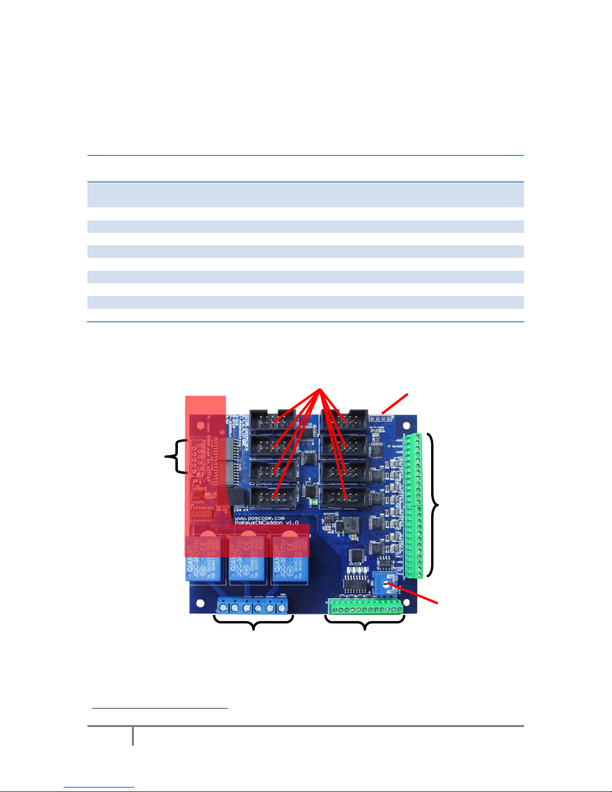
Description .............................................................................................................................................. 3
Pulse generator selection.................................................................................................................... 6
PoKeys device pins in use........................................................................................................................ 7
Integrated pulse generator - up to 3 axes at 25 kHz step frequency.................................................. 7
External pulse generator with dedicated IO capability - up to 8 axes at 125 kHz step frequency ..... 8
10-pin motor driver connector pinout ............................................................................................ 9
Dedicated axis switch inputs ........................................................................................................... 9
Relay outputs................................................................................................................................... 9
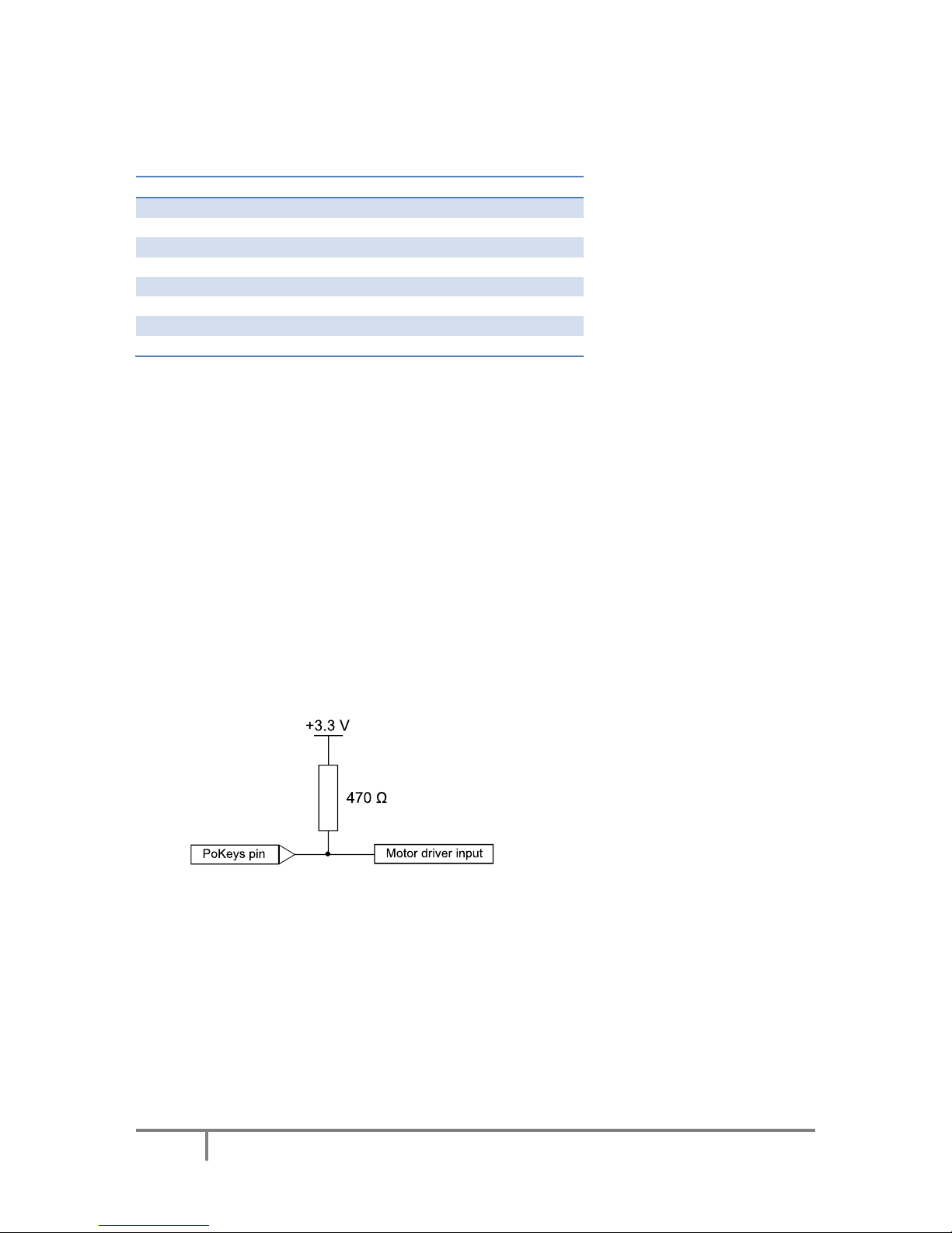
Open-collector outputs ................................................................................................................. 10
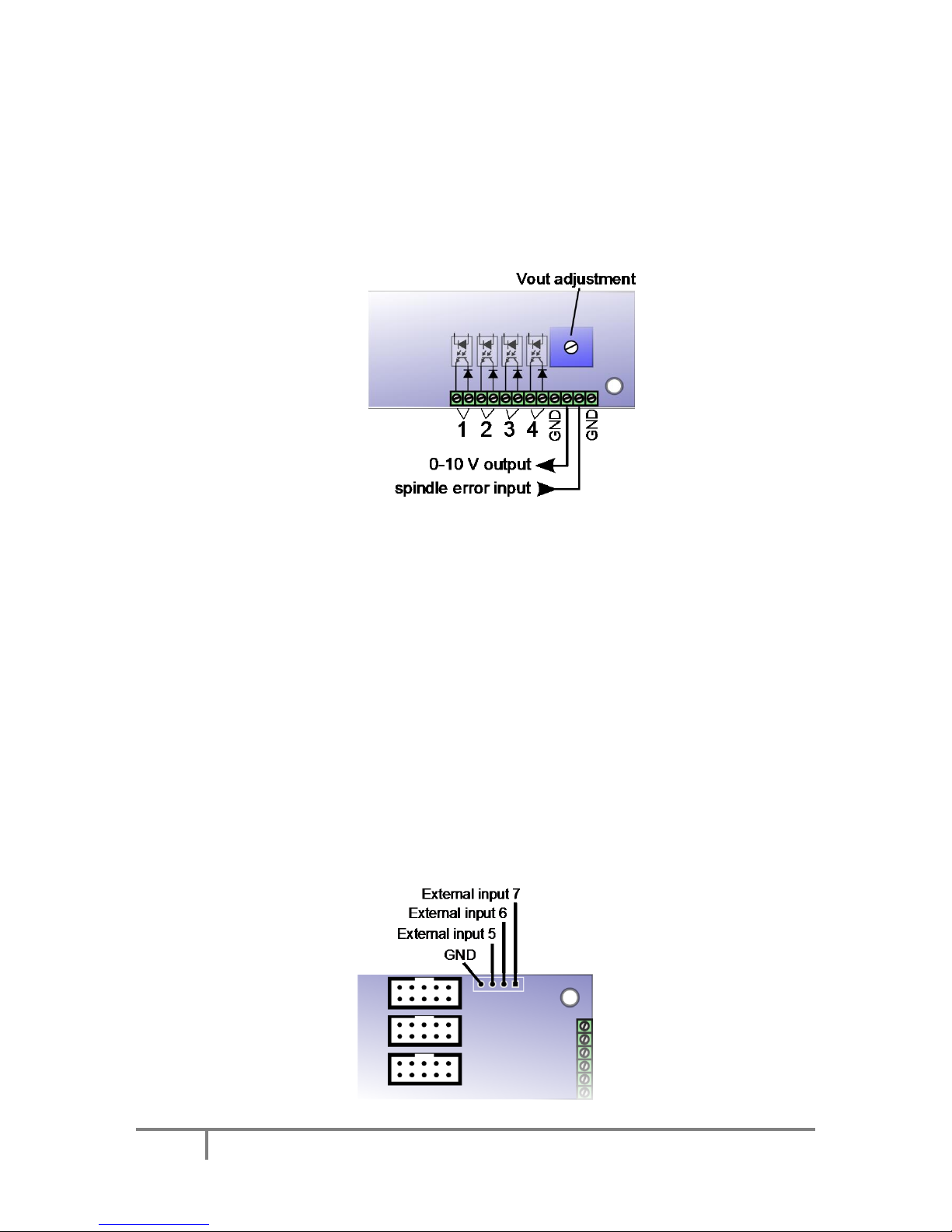
0-10 V voltage output.................................................................................................................... 10
Additional digital inputs ................................................................................................................ 10
Pulse engine limitations: ....................................................................................................................... 11
PoKeys Mach3 plugin ............................................................................................................................ 12
Installing plugin ............................................................................................................................. 12
PoKeys Mach3 plugin existing functionality.................................................................................. 12
Configuring plugin for the first time.............................................................................................. 12
Enabling Pulse engine.................................................................................................................... 14
Motors/axis setup ......................................................................................................................... 15
Axis switches configuration........................................................................................................... 17
Setting up digital inputs and outputs mapping............................................................................. 18
Pendant mode ........................................................................................................................... 19
PoPendant configuration....................................................................................................... 20
Encoder (MPG) settings................................................................................................................. 21
MPG (manual pulse generator) setup....................................................................................... 21
PoKeys IO status ............................................................................................................................ 26
Other (miscellaneous) settings...................................................................................................... 26
Reading and writing of IO from VB script...................................................................................... 27
Example script (finds the PoKeys device with the serial number 25000, then toggles the IO 1
on and off at a rate of 1 Hz): ..................................................................................................... 28
Additional OEM buttons................................................................................................................ 29
Additional OEM LEDs..................................................................................................................... 29
Pulse engine v2 operating principles..................................................................................................... 30
Modes of operation........................................................................................................................... 31

PoKeys Pulse engine v2 documentation
5
www.poscope.com
Safety charge-pump output .............................................................................................................. 32
Motor driver enable outputs............................................................................................................. 32
Axis parameters................................................................................................................................. 32
Custom external pulse generator without IO functionality .............................................................. 32
Frequently asked questions .................................................................................................................. 35

PoKeys Pulse engine v2 documentation
6
www.poscope.com
Pulse generator selection
Pulse engine supports different pulse generators:
-Integrated pulse generator (for up to 3 stepper motors with step frequencies up to 25 kHz)
-External pulse generator without dedicated IO capabilities (for up to 8 stepper motors with
step frequencies up to 125 kHz) using PoExtensionOC16 or third-party custom board.
-External pulse generator with dedicated IO capabilities (for up to 8 stepper motors with step
frequencies up to 125 kHz, dedicated limit+, limit-, home/ref, axis error inputs, 3 relay
outputs, 4 open-collector outputs, 0-10 V output) using PoKeysCNCaddon (pictured below).
PoKeysCNCaddon inputs and outputs are galvanically isolated from PoKeys board.
Figure 2: PoKeysCNCaddon v1.0

PoKeys Pulse engine v2 documentation
7
www.poscope.com
PoKeys device pins in use
Integrated pulse generator - up to 3 axes at 25 kHz step frequency
Pin
Function
38
Direction output –x
39
Direction output –y
40
Direction output –z
46 !
Step output –x
48 !
Step output –y (external 470 Ωpull-up resistor required)
49 !
Step output –z (external 470 Ωpull-up resistor needed)
52
Emergency switch input
53
Safety charge pump 5 kHz output
Inputs for limit, home and probing switches can be freely connected to any PoKeys pin and
configured in software.
Remarks:
-Watch for pin 47! It is not used for step output!
-All switch inputs expect normally closed (NC) switches and must be connected between
specified PoKeys input pin and ground.
-We advise adding an additional 1 kΩpull-up resistor on pins with an external switch
-Emergency switch must be connected in such way so that it cuts the power supply to the
motors when the switch is activated.
External pull-up resistor wiring for pins 48 and 49

PoKeys Pulse engine v2 documentation
8
www.poscope.com
External pulse generator with dedicated IO capability - up to 8 axes at 125
kHz step frequency
1
Please pay attention to connecting the PoKeysCNCaddon to PoKeys device. PoKeysCNCaddon
connects to PoKeys using the Expansion port flat cable, attached to the board. The Expansion port
signals should be connected to PoKeys as follows:
Pin
Description
PoKeys56U
pin
PoKeys56E/57E
pin
1
(red)
5 V power supply to the PoKeysCNCaddon - must supply at
least 400 mA for correct operation
5 V
5 V
2
PoKeys ground (not to be used for PoKeysCNCaddon IO)
GND
GND
3
PWM signal for 0-10 V output
17-22
17-22
4
Signal for IO capabilities (output)
38
38
5
Signal for IO capabilities (output)
37
37
6
Signal for IO capabilities (output)
36
36
7
Signal for IO capabilities (input)
35
35
8
Signal for pulse generation
23
9
9
Signal for pulse generation
25
11
10
Signal for pulse generation
26
51
1
Note that PoKeys Mach3 plugin supports only 4 axes
10-pin connections to motor drivers
PoExtension
connector
3 NO relay contacts
8x
Limit-
Home/Ref
Limit+
signals
4 OC outputs, 0-10 V output, Spindle error, GND
Vmax adjustment
3 additional digital inputs
Red = galvanically
connected to
PoKeys

PoKeys Pulse engine v2 documentation
9
www.poscope.com
10-pin motor driver connector pinout
Dedicated axis switch inputs
All inputs have built-in pull-up resistor - switches must be connected between GND (on the
PoKeysCNCaddon) and the correspoding input. Select 'Dedicated pin' in the axis settings.
Pin (from
top to
bottom)
Function
Pin
(continued
)
Function
-AX8
Limit- for axis 8
-AX4
Limit- for axis 4
RefAX8
Ref/home for axis 8
RefAX4
Ref/home for axis 4
+AX8
Limit+ for axis 8
+AX4
Limit+ for axis 4
-AX7
Limit- for axis 7
-AX3
Limit- for axis 3
RefAX7
Ref/home for axis 7
RefAX3
Ref/home for axis 3
+AX7
Limit+ for axis 7
+AX3
Limit+ for axis 3
-AX6
Limit- for axis 6
-AX2
Limit- for axis 2
RefAX6
Ref/home for axis 6
RefAX2
Ref/home for axis 2
+AX6
Limit+ for axis 6
+AX2
Limit+ for axis 2
-AX5
Limit- for axis 5
-AX1
Limit- for axis 1
RefAX5
Ref/home for axis 5
RefAX1
Ref/home for axis 1
+AX5
Limit+ for axis 5
+AX1
Limit+ for axis 1
Relay outputs
PoKeysCNCaddon board features 3 relay outputs with normally-open
contacts.
Rating:
-max. 7A/240VAC, max. 10A/125VAC or max. 10A/28VDC.
-AX8
RefAX8
+AX8
-AX7
RefAX7
+AX7
-AX6
RefAX6
+AX6
-AX5
RefAX5
+AX5
-AX4
RefAX4
+AX4
-AX3
RefAX3
+AX3
-AX2
RefAX2
+AX2
-AX1
RefAX1
+AX2
Pin
Function
1
Axis enable output
3
Direction output
5
Step output
7
Error input
2, 4, 6, 8, 10
GND
9
Not connected

PoKeys Pulse engine v2 documentation
10
www.poscope.com
Open-collector outputs
PoKeysCNCaddon board features 4 open-collector outputs with LEDs for signaling the output state.
Rating:
-Maximum applied voltage: 80 V
-Maximum DC current: up to 50 mA
0-10 V voltage output
PWM signal is used to create the 0-10 V voltage output. PWM signal with 0% duty cycle produces 0 V
on output, while 100% duty cycle produces Vmax on output. Vmax can be adjusted using the
potentiometer 'Vout'.
In order to convert PWM signal to an analog output, a low-pass filter with the time constant of 1 ms
is applied to the source signal. In order to avoid ripples in the analog output, use PWM frequency of
10 kHz or more.
Setup/calibration: either set the duty cycle to 100% or connect the PWM signal input to
PoKeysCNCaddon board (pin 3) to +3.3V. Use the multimeter to measure voltage between GND adn
0-10 V output. Use the Vout adjustment potentiometer to adjust the voltage to 10 V (
Additional digital inputs
There are 4 additional digital inputs: spindle error input and 3 general purpose external digital inputs,
available on the top right corner of the PoKeysCNCaddon board.

PoKeys Pulse engine v2 documentation
11
www.poscope.com
Pulse engine limitations:
-Minimum/maximum position:
oInternal motion controller: -/+ ~16.8 million ticks
oExternal (buffered) mode: -/+ ~2100 million ticks

PoKeys Pulse engine v2 documentation
12
www.poscope.com
PoKeys Mach3 plugin
Installing plugin
In order to install PoKeys Mach3 plugin, simply copy the Pokeys.dll to the Mach3 plugin folder (by
default C:\Mach3\Plugins\). Also, install the latest PoKeys software using the provided setup file.
PoKeys Mach3 plugin existing functionality
-3-/4-axis CNC machine support
-Support for PoKeys55, PoKeys56U, PoKeys56E and PoKeys57E devices
-Mapping of PoKeys digital inputs to Mach3 OEM LEDs and OEM buttons
-Mapping of Mach3 OEM LEDs to PoKeys digital outputs
-Mapping of PoKeys encoders to Mach3 DROs
-Support for matrix keyboard
-Support for kbd48CNC keyboard on I2C address 1
-Support for PWM outputs
-Support for alphanumeric LCD display
-Support for analog inputs (analog joystick, analog to DRO mapping, offsets and gains
adjustment, automatic calibration)
-Support for IO mapping (Mach3 native input-output pins, additional 100 Mach3 IO device
pins - device name PoKeys_{serial number})
-Dedicated menu for each device
-Support for pendant with the activation switch
-Usage of PoKeys Pulse engine (available on PoKeys56U and Pokeys56E devices) as external
motion controller for Mach3
-Safety charge pump output on pin 53
-External motion controller homing support
-Soft-limits and limit-override support
-Probing support
Configuring plugin for the first time
Open Mach3 and go to Config -> Config plugins.. The following dialog will appear.

PoKeys Pulse engine v2 documentation
13
www.poscope.com
Enable the Pokeys-Polabs plugin and click CONFIG to start configuring the plugin. PoKeys plugin
support multiple PoKeys devices (PoKeys55, PoKeys56U and PoKeys56E). To add a new device
configuration, click the ‘Add new’ button and select the PoKeys device (as illustrated in the image
below).
After new device configuration is added, Mach3 MUST BE RESTARTED!
After restart, the option ‘Configure’ is enabled. This opens the device configuration dialog where user
can configure the device. The same can be achieved using a dedicated device menu entry in the
Mach3 Plugin Control menu.

PoKeys Pulse engine v2 documentation
14
www.poscope.com
Enabling Pulse engine
In order to use Pulse engine support, go to device configuration, switch to ‘Pulse engine’ tab and
enable one of the following options:
-Integrated 3ch: use the integrated pulse engine support in PoKeys56U and PoKeys56E. This
option supports step frequencies up to 25 kHz
-External 4ch without IO: use the pulse engine with conjunction with a simple external pulse
engine adapter. This option supports step frequencies up to 125 kHz.
-External 4ch with IO: use the pulse engine with PoKeysCNCaddon external boards. This
option supports step frequencies up to 125 kHz.
After selecting one of the options above, click OK and restart Mach3 in order to allow Mach3
recognize an external motion controller.
On the next Mach3 startup, the following dialog will appear, notifying you that the motion control
hardware plugin was detected. Select PoKeys-Polabs and click OK.
To enable Pulse engine, the emergency switch input must be connected between pin 52 and
ground. The switch must be NC (normally closed) type.
At this step, configure the axes as normally through Config -> Motor tuning. See below for details.

PoKeys Pulse engine v2 documentation
15
www.poscope.com
Motors/axis setup
Open Config > Ports & Pins. The following dialog will appear.
Please check that the X, Y and Z axis are enabled (enable A Axis if external pulse generator is used).
Other settings are ignored.
After enabling the axes, open the Motor tuning dialog (Config > Motor tuning).
Follow the Mach3 motor tuning procedure to setup the appropriate values for ‘Steps per’, ‘Velocity’
and ‘Acceleration’ for each axis. The ‘Step pulse’ and ‘Dir pulse’ options are IGNORED.
To setup Home/Soft Limits, go to the menu Config > Homing/Limits. In this dialog, software limits and
homing speeds can be setup. Use the 'Reversed' and 'Home neg' options to setup the axes directions.
Please note that 'Slow Zone' is not supported.

PoKeys Pulse engine v2 documentation
16
www.poscope.com

PoKeys Pulse engine v2 documentation
17
www.poscope.com
Axis switches configuration
In order to configure the axis switches, open Device configuration (either via Config Plugins or via a
dedicated device configuration menu in Plugin Control main menu in Mach3) and switch to Pulse
engine settings tab. The following dialog appears.
There is a separate drop-down menu for each available switch. If external pulse engine with IO
functionality is selected, external dedicated option can be selected in the menu for each switch or a
standard PoKeys digital input pin (the latest is the only option to use when using integrated pulse
engine or external pulse engine without IO functionality).
Home/ref switch has some additional options:
-Shared with Limit-: Limit- switch functions both as Limit- and as home position switch.
During homing, Limit- functionality is temporarily disabled
-Shared with Limit+: same as above, but with Limit+ switch
All switches can be inverted - the green/red blocks on the left of the switch selection options display
the current switch status, with green indicating a free (non-tripped) switch and red indicating tripped
switch. Use the 'Invert' option to switch between the states if necessary.
If limit switches are enabled, PoKeys Pulse engine will enter emergency mode if any limit switch gets
triggered.
The probing input option is available at the bottom of the dialog and offers mapping the probing
input to either external digital inputs or PoKeys digital input pins.

PoKeys Pulse engine v2 documentation
18
www.poscope.com
Setting up digital inputs and outputs mapping
To access the digital inputs and output mapping, open the menu PlugIn control > Configure PoKeys
{your serial number}.
The following dialog will appear
First column displays a list of all inputs or outputs, available on your PoKeys device. Use the tree
structure to navigate between different peripherals and their IO pins.
The second column displays the pin function. If the pin is assigned a special function, a description of
this function will be displayed. If multiple special functions are assigned, a red 'Conflict' warning will
be displayed.
Third column (available for digital inputs and outputs) enables selection of mapping to Mach3 OEM
LEDs. If the pin function is set to 'Input', this mapping will enable setting of Mach3 OEM LED state
based on PoKeys IO pin state. If the pin function is set to 'Output', Mach3 OEM LED state will be
reflected to PoKeys IO pin state.
Fourth column (available only for digital inputs) enables selection of IO mapping to Mach3 OEM
buttons. When PoKeys IO pin is triggered, the selected Mach3 OEM button will be triggered also.
Fifth column (available for digital inputs and outputs) enables selection of mapping to/from Mach3
IOs (outputs, such as spindle relay, vacuum, … used internally by Mach to control different external
devices and inputs, such as limit, home switches, … used internally by Mach to detect the status of
the machine) and Mach3 IODevice inputs and outputs (accessible via VBScript).
PoKeys digital
input or output
Selected IO
function
Mapping to
Mach3 OEM LED
Mapping to Mach3
OEM button
Mapping to Mach3
IOs
Use invert option to
invert the digital
input or output state

PoKeys Pulse engine v2 documentation
19
www.poscope.com
Pendant mode
Plugin supports the usage of pendant with activation switch. If such pendant is connected to PoKeys,
'Pendant mode' should be enabled (checkbox at the bottom of the 'PoKeys mapping' dialog). In this
mode, jog action will be deactivated when the activation switch is released and will be automatically
activated when there is a signal detected for both the axis and step selection.

PoKeys Pulse engine v2 documentation
20
www.poscope.com
PoPendant configuration
Use the following table to configure PoPendant with Mach3. Activate 'Pendant mode' in Mapping
page in order to activate the MPG jogging activation/deactivation using the 'Control switch' on the
side of the PoPendant.
The configuration can also be downloaded (see PoPendant homepage) and imported into Mach3 (go
to Import/Export tab in plugin configuration and select 'PoKeys pin mapping' and 'Encoder settings
and mapping', then click on 'Import' and select the PoPendant configuration file).
Note: the following table only gives an example on how to connect the PoPendant to PoKeys
device. To ease the setup process, the configuration file for this example is provided on PoPendant
homepage. Wiring can be rearranged by the user, but the plugin configuration must be adjusted
accordingly.
If PoKeys Pulse engine is used, 'Let PoKeys handle MPG jogging' must be checked in encoder
configuration page.
Figure 3: PoPendant internal wiring
Wire
PoPendant
"wire colour"
Function
PoKeys pin
number
Mach3
Mapping
1
red
MPG +5V
5V
/
2
black
MPG GND
GND
/
3
green
MPG A
1
MPG1 B
4
white
MPG B
2
MPG1 A
3*
purple
N.C.
N.C.
/
4*
purple/black
N.C.
N.C.
/
5
green/black
Lamp +
+3.3V
/
6
white/black
Lamp -
14
DO LED 57
7
yellow
X axis
19
Button 185
8
yellow/black
Y axis
20
Button 186
9
brown
Z axis
21
Button 187
10
brown/black
A axis
22
Button 188
9*
pink*
B axis
24
Button 189
10*
pink/black*
C axis
27
Button 190
11
gray
x1
3
Button 191
12
gray/black
x10
4
Button 192
13
orange
x100
7
Button 193
14
orange/black
Ctrl Switch
GND
/
15
Light blue
Estop
52
IO Estop**
16
blue/black
Estop GND
GND
/
17
red/black
N.C
N.C.
/
shield
shield
GND
/
* Not available on all units
** Don't configure Estop mapping if pulse engine is
enabled
N.C.= not connected
DO = digital output
DI = digital input
This manual suits for next models
2
Table of contents
Popular Engine manuals by other brands

TDI
TDI TURBOTWIN T30ML Installation and operating manual

STEYR MOTORS
STEYR MOTORS MO114K33 Operation, maintenance and warranty manual

IAME
IAME X30 125cc RL - TaG Assembly instructions & user manual

Leroy-Somer
Leroy-Somer LSA 47.2 Installation and Maintenance

Himax
Himax HA3618 Series manual

Pride Mobility
Pride Mobility DRVMOTR1269 Technical instructions

helvenco
helvenco AERO 1000 owner's manual

Perkins
Perkins 1206F-E70TA Operation and maintenance manual

RHINO MOTION CONTROLS
RHINO MOTION CONTROLS RMCS-2302 Installation Manual and Datasheet

Man
Man D 2840 LE 403 operating instructions

KIRLOSKAR
KIRLOSKAR R1040 Operation & maintenance manual

Kohler
Kohler LOBARDINI 15 LD 400 Use & maintenance